Abstract
2. In the shear wall reinforcement of a high-rise residence in Changzhou, China, the prestressed steel bar reinforcement method is innovatively used. This paper focuses on the reinforcement principle and construction method of the prestressed steel bar method for strengthening the shear wall. During the construction, combined with the engineering quality problems, the prestressed steel bar method is used to strengthen the shear wall. This method avoids the reduction of the use area caused by the increasing section reinforcement method and the stress lag caused by the replacement method, does not change the structural stiffness and the shape of structural members, and shortens the construction period. After monitoring by the monitoring unit, the reinforcement method has good effect. This study also passed the acceptance of the science and technology plan project of the Ministry of construction, and formed a complete set of construction method of prestressed steel bar strengthening shear wall. The effective implementation of this method can provide technical reference for the reinforcement construction of similar projects.
1. Introduction
Prestressed steel bar, also known as PC steel bar, is an intermediate type prestressed product between finish rolled rebar and prestressed steel strand. It has the advantages of high strength, high toughness, low relaxation, strong binding force with concrete, good weld ability, upsetting and material saving [1]. It has been widely used in concrete centrifugal pipe pile, electric pole, elevated pier, railway sleeper and other high-strength prestressed components, and its application field has expanded from railway and highway to construction, water conservancy, energy and geotechnical anchoring engineering fields.
In recent years, the application research of prestressed steel bar has developed to a certain extent. For example, Shangguan Junwei [2] studied to determine the steel bar parameters of roadway support through the relationship between surrounding rock layers of roadway, and achieved the engineering purpose of basically no separation of roadway roof through the joint roof support of steel bar and anchor cable. Xu Jinhong [3] studied the reinforcement of weakly cemented rock stratum with high prestressed steel rod and anchor cable support through experiments, which meets the normal use of roadway well. Yao Yi [4] also found through research that prestressed steel bars play a significant role in active support in roadway support, the supported roadway deformation is small, and the roof is basically free of separation. Wu Yongzheng [5, 6] and others have carried out the mechanical property test of mining prestressed steel bar by means and methods of laboratory test, numerical simulation and field test, and carried out the development and Application Research of complete set of steel bar support technology. It is found that under high prestress, the active support effect of steel bar is obvious, and has the advantages of high prestress application level, low cost and good support effect. Wang Bangping [7] carried out the research on the application of prestressed steel bar in the vertical prestress of the web of prestressed concrete continuous beam bridge. Through the research, it is found that the use of unbonded prestressed steel bar in continuous beam bridge has the advantages of excellent material performance, simple construction process, reliable acceptance method and easy implementation compared with prestressed finish rolled rebar. Deng Ming [8] and others used prestressed steel bars to strengthen the T-beam diaphragm to solve the problem of cracking and damage of the diaphragm of the T-beam bridge. It was found that the crack width of the diaphragm and the deflection of the main beam were greatly reduced. Fang Minhua [9] conducted an experimental study on the mechanical performance of PC steel rod prestressed concrete roof slab, and found that PC steel rod used for prestressed concrete roof slab has good stress and obvious omen before failure, which improves the mechanical performance of general prestressed concrete flexural members. Through collection, it is found that the existing research on prestressed steel bars mainly focuses on bridge construction and roadway support. It is found that the application advantages of prestressed steel bars are obvious in bridge construction and roadway support. However, there are few studies on prestressed steel bars in civil buildings. In this case, we combined with the quality defects of the project, compared and selected the reinforcement scheme, innovatively adopted the prestressed steel bar to strengthen the shear wall, and achieved good results, hoping to provide effective reference for the reinforcement of other engineering structures.
2. Engineering case
2.1. Engineering survey
A high-rise residential building in Changzhou has 24 floors above ground and 2 floors underground, with a building height of 98.900 m. The main structure have been capped. The infilled wall and secondary structure of the upper structure have been completed. The quality supervision station found that the rebound strength of the local shear wall concrete on the bottom floor is lower than the designed strength. The testing unit found that the concrete strength of the shear wall of 12 floors and below is mostly low. The structure with more than 12 stories is normal. Based on the test results and the structural recheck conclusion of the original design unit, the professional design unit has designed the reinforcement of the components whose original concrete strength does not meet the requirements of the project. For some shear wall structures, the shear wall reinforcement measures of local shear wall embedded steel bar applying stress method and covering the wall surface with steel mesh and spraying composite mortar ductility treatment have been taken.
2.2. Principle of shear wall strengthened by prestressed steel bar
In the shear wall to be reinforced, a 250 mm wide vertical groove shall be set by mechanical and manual chiseling. During the chiseling process, the wall reinforcement shall be retained as much as possible, and the wall naturally forms a roughened surface, which shall be set in the groove Φ100 steel rod column (see Figs. 3 and Fig. 4 for details, and Fig. 5 for site photo).
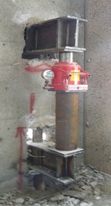
End plates of 200×150×20 are set at both ends of the steel rod column to facilitate jacking with the upper and lower shear wall concrete, and are vertically welded on the steel rod column Φ16. The number of studs connected with the upper and lower shear walls shall be determined according to the calculation, and the number of studs connected with the shear wall of the layer to be reinforced shall be set according to the structural requirements. The steel bar column passes through the steel beam with force placed in the wall before the beam is set up (perpendicular to the wall surface at the trough body) and is firmly welded with the simultaneous interpreting steel beam. Meanwhile, a counterforce steel beam is erect in the wall above the tank body, and a pair is arranged between the two H type steel beams. Φ180×8 force transmission steel pipe and Jack (see Fig. 6 for details) to ensure the setting Φ100 steel rod column can work together with shear wall.
Fig. 1Principle of prestressed steel bar reinforcement method
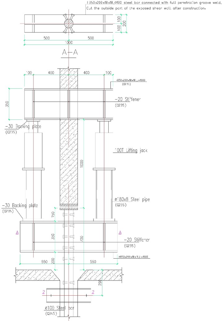
Fig. 2Elevation of prestressed steel bar column in shear wall
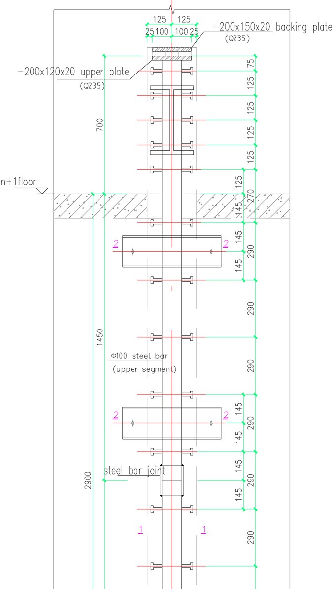
Fig. 3Sample of steel bar
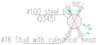
Fig. 4Sample of steel bar joint
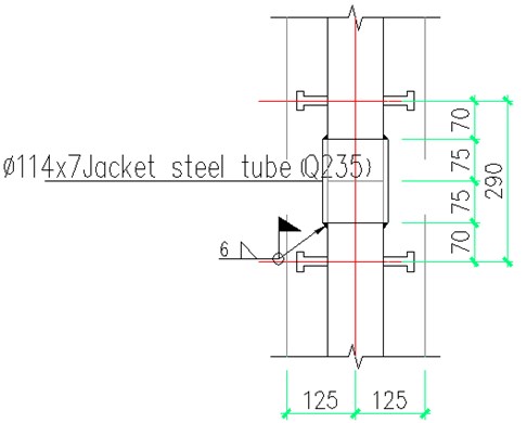
Fig. 5Site photo of steel bar
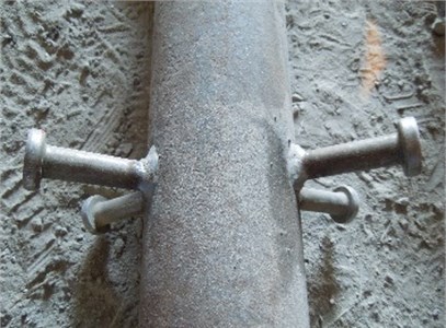
Fig. 6Site drawing of steel beam setting
According to the design requirements, the steel rod is prestressed through force transfer steel beam. After the prestress is applied to the design requirements by Jack, the steel wedge is used to knock the upper part of the steel rod and the wall tightly and weld firmly. The damaged part of the wall is welded with reinforcement of the same specification and restored to the original state, and then closed with formwork, The vertical slot in the shear wall shall be poured with non shrinkage cement-based grout with coarse aggregate. After the measured strength of the newly poured concrete in the vertical slot meets the requirements, the pressurizing equipment shall be removed, the force transfer steel pipe and reaction frame steel beam shall be removed, and the exposed force transfer steel beam shall be cut off. During construction, temporary measures shall be taken to ensure stability of newly added prestress Φ100 steel rod column. After construction, the stability of prestress Φ100 steel rod column is guaranteed by shear wall.
In the reinforcement of building structure, the newly added part of the structure belongs to secondary stress. Before reinforcement, the original structure has been under the action of external force load, and the cross-section stress and strain level are generally very high. The newly strengthened part of the structure will be stressed only when the strengthened structure further bears the load, that is, the second load, so that the stress and strain in the newly added part always lag behind the stress and strain of the original structure, that is, there is a phenomenon of strain lag. This will result in high stress and large deformation of the original structure, while the stress of the newly added part is still at a low level, which cannot give full play to its role and cannot play its due reinforcement effect. Secondly, the reinforced structure belongs to the secondary stress combination structure, and the old and new parts still have the problem of overall work and common stress. The technology of strengthening shear wall with prestressed steel bar solves the problem of strain lag by applying prestress on the prestressed steel bar, anchoring the upper and lower ends of the prestressed steel bar with the shear wall with epoxy resin concrete, and then strengthening the connection with the shear wall through cylindrical head studs welded on the steel bar, which effectively ensures that the stress of the prestressed steel bar reaches or even exceeds the original shear wall. The overall performance of the whole reinforcement system is improved.
3. Methods
3.1. Main construction materials, models and specifications
(1) Support system, unloading steel and steel pipe material: Q235B;
(2) Steel bar: 100 mm, Q345;
(3) Supporting steel pipe: 180 mm × 8 mm;
(4) Grouting materials for pouring: Class IV cement-based grouting materials (C50 strength grade grouting materials shall be used below the elevation of 14.450 mm, and C40 strength grade grouting materials shall be used above the elevation of 14.450 mm);
(5) Structural adhesive: JK building structural adhesive;
(6) Chiselling machine: Hilti TE76 electric hammer;
(7) Jack for jacking: 100t, accuracy of oil pressure gauge is grade 1.5;
(8) Settlement observation equipment and stress-strain monitoring device.
3.2. Construction technology
Removal of obstacles at the construction site → setting out and positioning of embedded steel bars at the shear wall site → slotting of shear wall → erection of steel bars and support system → stressing of steel bars → grouting of the notch tightly → removal of supporting auxiliary components after the grouting strength reaches C30 → binding and welding of steel mesh → painting or spraying of 30 mm thick high-performance composite mortar → maintenance → putting into use.
3.3. Construction method of steel bar embedded in shear wall
Construction technology: positioning and setting out → roughening the surface of shear wall → opening installation slot of shear wall → opening and installation of steel beam of reaction frame → installation of steel bar and support system → acceptance of installation quality of reaction frame and steel bar → embedded installation monitoring system → prestressing steel bar by stages → fixing the upper pressure end of steel bar → unloading by stages → adjustment of original beam and wall reinforcement → formwork erection → pouring Slurry → formwork removal → curing → cutting off the lateral support of the force transmitting steel beam and the fixed steel bar.
(1) According to the requirements of the drawings, the location of the embedded steel bars shall be set out and rechecked in combination with the size of the completed members. In order to avoid the edge members with more reinforcement, the prestressed steel bars shall be symmetrically set inside the edge members of the shear wall.
(2) In the setting out position of the wall, the 250 mm wide wall through slot and the top shear wall through the hole where the horizontal temporary support steel beam is placed are to be chiseled mechanically and manually. During the construction, the steel bars in the original wall body shall not be damaged as much as possible, and other main structures shall not be damaged.
(3) According to the requirements of the design drawings, the shaped steel bar shall be made in the processing plant. When the steel bar is cut, the cutting section shall be flat and perpendicular to the centre line of the steel bar. The welding between the bolt and the steel bar shall be carried out according to the angle and position of the drawing. The temporary horizontal force transmitting steel beam (H350 × 220 × 20 × 20) part of the bolt can be welded on site. The steel bar and the force transmitting steel beam shall be connected by full penetration groove weld.
(4) The steel bar and auxiliary jacking support system are set up in the groove. The vertical connection of the steel bar is welded with Φ114 × 7 sleeve (Fig. 6), and the verticality of the steel bar is strictly checked. The steel bar in the middle layer is equipped with [16 channel steel and M12 U-bolt, so as to ensure the lateral stability of the steel bar in the centre of the wall and the side of the steel bar. Pour the epoxy resin concrete at the lower cushion beam, and complete the anchoring of the lower cushion beam.
(5) According to the requirements of the drawings, the upper flange of the reverse support steel beam shall be placed close to the upper part of the hole, the lower part shall be supported by Jack, and the steel plate and concrete contact surface shall be filled with modified epoxy slurry to ensure the compactness of the structural adhesive and the flatness of the upper and lower surfaces of the steel beam; after the grouting material near the steel beam reaches the specified strength, the jack and Φ180 × 8 supporting steel pipe can be set on the force transmitting steel beam, and the jack and steel The contact surface of the beam shall be smooth, the contact surface of the steel pipe and the jack shall be set with 30 thick steel base plate, and the centre line of the jack and the stiffener of the force transmitting steel beam shall coincide.
(6) According to the stress value applied in the design, two jacks are used to apply prestress to the steel bar step by step. The first load is 30 % of the required stress value, the second load is 60 %, the third load is 90 %, the fourth load is 100 % of the required stress value, and the interval time is 10 min. The data of relevant stress changes are collected, and the stress value is adjusted according to the data, so as to ensure the reliability of the steel bar Effective stress.
(7) After the stress value meets the design requirements, it shall meet the design requirements. Knock the steel wedge between the base plate and plug weld the gap between the steel bar and the upper base plate firmly. Anchor the upper end of the steel bar with epoxy resin and remove the jack and unloading steel beam.
(8) After finishing the concrete, the reinforcement at the original structure of the notch shall be repaired and recovered. The cut-off reinforcement in the construction shall be connected and welded as required. The length of the welding overlap shall meet the design requirements. The crossing of the reinforcement shall be bound with iron wire. After the formwork is erected, the original section of the wall shall be restored by pouring the grouting material, and the test block shall be reserved and maintained as required by the specification. According to the test report of test block, determine the time of formwork removal, and check the appearance quality after formwork removal. If there are honeycomb and pockmarks, handle them according to the severity.
(9) The temporary support of steel bar shall be removed after the strength of grouting material reaches the requirements.
3.4. Construction method for ductility treatment of shear wall
Construction process: removal of obstacles at reinforcement part → wall chiselling treatment → surface cleaning → binding and welding of reinforcement mesh on wall surface → planting and installation of tie bars → cleaning, wetting and brushing interface agent on new and old joint surface → construction of composite mortar surface (spray construction) → maintenance.
(1) The wall surface shall be roughened and provided with 5mm deep groove.
(2) Before the spraying of cement composite mortar, the steel mesh shall be concealed for acceptance, and the next process can be carried out only after the acceptance is qualified.
(3) Before spraying the composite mortar, the spraying thickness mark shall be set with the spacing of about 1000 mm.
(4) Before spraying, the air compressor and jet machine shall be put into trial operation. After inspection and operation, air supply test and water supply test shall be carried out for composite mortar pipeline, and no air leakage and water leakage shall occur.
(5) Check the ventilation and lighting of the work area.
(6) Before spraying construction, spray water on the surface to be sprayed and wet, and brush the interface agent.
(7) When spraying, the distance between the nozzle and the spraying surface should be 1.0 m, and the nozzle should be vertical to the spraying surface.
(8) The spraying operation shall be carried out in the sequence of section and block, part first, then whole and bottom-up. During spraying, the nozzle moves slowly and repeatedly in a spiral shape, with a spiral diameter of about 20-30 cm, so as to ensure dense spraying.
(9) During the spraying construction, the water cement ratio shall be well controlled to keep the surface of the spraying mortar flat and free of dry block sliding and flowing.
In addition, the rebound rate of spraying composite mortar shall be controlled, which shall not be greater than 20 % on the side and 30 % on the top. Rebound materials falling on the ground should be collected and broken in time to prevent caking. The solid elastic material shall be screened and classified, and the material diameter can be reused if it meets the quality requirements of the above raw materials. The contaminated rebound material shall not be used for structural reinforcement.
(10) After the thickness of spraying composite mortar meets the design requirements, it shall be scraped and trowelled. The levelling shall be carried out in time after the initial setting of mortar. It is not allowed to disturb the internal structure of the mortar and its bonding with the base course. After the final setting of the last layer of spraying mortar for 2 h, spray water for curing. The curing time shall not be less than 14 d.
4. Results
4.1. Construction monitoring
(1) Monitoring purpose.
In the process of structural reinforcement, the internal force and displacement of each stressed component are monitored to ensure the reliability of reinforcement.
(2) Monitoring basis.
Technical standard for inspection of building structures (GB/T 50344-2004);
Unified standard for construction quality acceptance of Building Engineering (GB50300-2013).
(3) Burying of monitoring points.
1) Embedding of internal force monitoring points of steel bars: according to the test requirements of the design unit and combined with the actual situation of construction, before the steel bars are stressed, two fiber grating reinforcement meters (Fig. 7) are arranged symmetrically on the steel bars to test the axial force of the steel bars in the loading, concrete pouring, unloading and other stages (see Table 1 for specific time nodes). Install a pair of FBG surface strain gauges on the steel bar to be tested, connect the demodulator and debug the peak wavelength of the FBG. Read the grating peak before loading as the initial peak. During the whole process, the computer will automatically read the peak value of the grating and convert it into the axial force of the steel bar:
Table 1Time node of internal force monitoring of steel bar
Reinforcement form | construction stage | Reading time | Reading content | Measuring means |
Steel bar | Pressurization stage | According to the construction requirements, pressurize by stages, and measure and read the axial force of steel bar at each stage | Internal force of steel bar | FBG surface strain gauge |
Concreting stage | Before pouring | |||
Within 3 days after pouring | ||||
Jack removal stage | 1 day after removal | |||
2 days after removal |
Fig. 7Position diagram of sensor layout
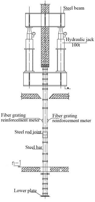
Fig. 8Position diagram of wall stress monitoring point
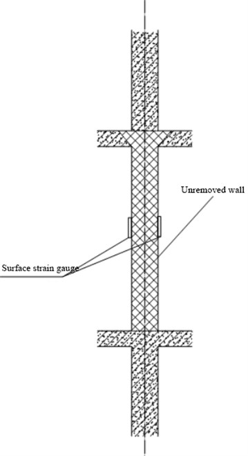
2) Embedding of wall stress monitoring points: before the change of wall stress, a pair of surface strain gauges shall be embedded at both sides of the measured wall, at the midpoint of the support structure connection (Fig. 8), and the readings shall be measured for three times, and the average value shall be taken as the initial reading of the measurement point. After the wall stress changes, the readings of the measuring points shall be measured again to obtain the wall strain, and the wall stress and the change of the reinforcement stress in the wall shall be calculated.
3) Embedding of displacement monitoring points: before jacking operation, the upper layer of the replacement layer shall be supported on the wall surface, and static level measuring points shall be set at the midpoint of the two support lines as the monitoring points for displacement measurement; static level observation points shall be set on the wall surface not affected by deformation as the reference points to observe the relative deformation between the reference points and the monitoring points.
(4) Acceptance criteria.
The qualified standard of the inspection lot shall be no more than 20 % of the loss axial force value specified by the designer, and the qualified judgment standard of axial force and vertical displacement shall be determined according to the technical standard for inspection of building structures (GB / T 50344-2004) (see Table 2).
Table 2Qualified standards for axial force and vertical displacement
Measurement contents | instrument | Eligibility criteria |
Axial force | Grating surface strain gauge; vibrating wire type reinforcement meter | ≥85 % |
Vertical displacement | Total station | < 0.01 % |
(5) Monitoring results.
In the process of reinforcement, the monitoring unit monitored the stress of steel bar and the deformation of shear wall in real time. Monitor the axial force of the steel bar during the loading process, 3 days after the concrete pouring in the reinforcement area, 1 day and 2 days after the removal of the loading device. The monitoring data show that the residual coefficient of the axial force of the prestressed steel bar is more than 0.85, and the residual coefficient of the axial force of most steel bars is more than 0.9, which meets the standard that the loss axial force value specified by the design unit is not more than 20 %. Before, after and 1 day after the replacement wall is removed the vertical displacement of the top plate of the replacement shear wall is monitored at all stages after the support is removed. The measured maximum cumulative vertical displacement is 0.2 mm, which meets the limit requirement of no more than 0.3 mm as required by the specification.
5. Conclusions
Among the existing structural reinforcement methods, the replacement concrete method does great damage to the original structure. Due to the secondary stress, the stress lag of the replaced shear wall is obvious, and the construction period is long; If the method of adding steel plate or section steel around the shear wall and column is adopted, it will affect the later decoration construction of residents, significantly reduce the use area of the house and increase the structural stiffness and self-weight. The prestressed steel bar reinforcement method overcomes the above shortcomings, not only ensures the reinforcement quality and user use area, but also shortens the construction period. After the completion of the reinforcement project, through the construction monitoring, it is found that the maximum prestress loss of the prestressed steel bar is 15 %, which meets the standard that the loss axial force value required by the design is no more than 20 %. The maximum cumulative deformation of the vertical displacement of the top plate of the replacement shear wall is 0.2 mm, which meets the limit requirement of less than 0.3 mm required by the specification. The structural reinforcement has also passed the on-site special acceptance of the science and technology plan project of the Ministry of construction. After being put into use for a period of time, the building operates well, achieves the expected reinforcement goal, and fully reflects that the reinforcement method is economical, safe and effective. On this basis, in order to facilitate the promotion of technology, we continue to summarize and form a complete set of construction methods.
References
-
C. Heping and Y. Wenchi, “Application of comprehensive reinforcement technology in high-rise building,” Archives of Civil Engineering, pp. 231–246-231-246, 2021, https://doi.org/10.24425/ace.2021.137165
-
Shangguan Junwei, “Application of support technology for separated roadway based on prestressed steel bar support,” (in Chinese), Mechanical Management and Development, No. 3, pp. 31–32, 2021, https://doi.org/10.16525/j.cnki.cn14-1134/th.2021.03.015
-
J. Xu, “Research on the support technology of the prestressed steel bar for the roadway affected by dynamic pressure of the weak cementation roof rock,” Mine Surveying, Vol. 45, No. 2, pp. 69–73, 2017.
-
Yao Yi, “Mechanical properties of prestressed steel bar and its application in roadways,” Mining Surveying, Vol. 46, No. 5, p. 32–36, 2018.
-
Y. Wu and J. Wu, “Laboratory study on mechanical properties of mine pre-stressed steel bars,” Coal Science and Technology, Vol. 48, No. 2, p. 21–27, 2020.
-
Y. Wu et al., “Development and application of mine prestressed steel bar supporting technology,” Chinese Journal of Rock Mechanics and Engineering, Vol. 34, p. 3231–3237, 2015.
-
B. Wang et al., “Application of vertical prestressed steel bars to the long-span prestressed concrete continuous beam,” Transportation Science and Technology, Vol. 278, pp. 60–61, 2016.
-
M. Deng et al., “Experimental study of t-type beam bridge transverse diaphragm reinforcement by prestressed steel bar,” Journal of Experimental Mechanics, Vol. 32, No. 4, pp. 535–542, 2017.
-
M. Fang, “Experimental study on load bearing behavior of prestressed concrete roof-slabs using pc steel wires,” Building Structure, Vol. 43, No. 18, pp. 74–77, 2013.
About this article

