Abstract
In order to improve the seismic performance of high-rise buildings, a friction damper installation scheme was proposed in the paper. Through numerical simulation and experimental testing, the vibration reduction effect was compared and verified. Herringbone structure was applied to install friction damper in the bearing wall. Based on this vibration reduction scheme, the finite element model of high-rise building was established, and the influence of damper on the modal characteristics of building frame was analyzed. It can be known that the damper has little influence on the natural frequency, but has a great influence on the amplitude range of the excitation response. In the finite element model, two kinds of seismic waves were applied, the strength and dynamic response was simulated and calculated, and the maximum deformation and stress results were obtained. Compared with the initial model, it can be known that the more intense the vibration is, the more obvious the damping effect of the damper is. A seismic excitation simulation system based on acceleration sensor detection is designed and applied to the wall vibration test. The results show that the maximum vibration acceleration of the measured point is reduced by 26.3 % by the damper, and the stable seismic effect can still be maintained during the impact of extension. Compared with the traditional hardness and volume reinforcement scheme, the friction damper can reduce the production cost and improve the adaptability to seismic wave excitation, which provides an important basis for seismic research in other fields.
Highlights
- Herringbone structure was used to install friction damper in the bearing wall.
- Compared with the initial model, it can be proved that the more intense the vibration is, the more obvious the damping effect of the damper is.
- A seismic excitation simulation system based on acceleration sensor detection is designed and applied to the wall vibration test.
1. Introduction
In the field of construction engineering, the seismic capacity of high-rise and complex buildings is obviously insufficient [1] in developing countries, due to the relatively poor structural system, design concept, codes and standards. Therefore, the economic losses and casualties caused by the same intensity of earthquake are more serious than those in developed countries. In recent years, the seismic isolation technology is more widely used in residential buildings. The seismic performance is greatly improved compared with traditional seismic structures, especially high-rise residential buildings [2]. There are lots of researches on the seismic performance of building structures, but so far, most research concentrates on the causes of vibration [3], excavation of weak structures, and seismic performance tests through experiments and simulation analysis methods. The representative ones are as follows: Jara [4] explained the collapse of weak story buildings observed during the earthquake, evaluated the seismic response, and determines the reliability indices of a typology of buildings with flexible ground floors; Hafner [5] performed a non-linear static pushover analysis, examined possible failure mechanisms and explained a conclusion process of the building’s usability; Mohammed [6] constructed three scaled models of steel skeleton structures with variable embedded depths, and the finite element technique is carried out for scaled and real models. Miah [7] proposed a building vibration reduction scheme with high anti-damping characteristics, of which vibration isolation effect is good, but the cost is high and the construction is relatively difficult. However, for the design of high-rise buildings, there is still a lack of a low-cost, high seismic performance wall strengthening method.
The optimal design of aseismic structures is of great significance to improve the quality of high-rise buildings and reduce the risk of accidents [8]. In addition, it can also effectively reduce production costs. For the energy dissipation and shock absorption design of the structure with given structural reinforcement and section size, the use of direct design method can reduce the iterative process and improve the efficiency of structural design [9]. Therefore, a design method for viscoelastic damper that can consider the multi-level seismic action is established in this paper, which avoids the iterative trial calculation process of the traditional design method. In addition, the wall strengthening scheme is proposed based on the damper performance, which can obtain good seismic performance at low cost and have good economic benefits.
2. Vibration reduction scheme of high-rise building
2.1. Requirements for vibration reduction design
Under the current seismic design requirements, improving the safety reserve of the structure by upgrading the small earthquake elastic design to the medium earthquake elastic design or even the large earthquake elastic design will obviously lack practicality due to the high economic cost, which is obviously not applicable in developing countries. Therefore, it is a relatively reasonable choice to allow the structure to enter plasticity to a certain extent to prevent brittle failure and collapse under the action of moderate earthquake, large earthquake and giant earthquake. The discreteness of the probability distribution of the response of the structure under random earthquake will be further amplified as the structure enters nonlinearity [10]. In order to safely consider the less favorable conditions, the structural seismic safety reserve needs to be further improved with the expansion of the discreteness of response distribution.
Taking multi-storey frame structure as an example, the uniformity of deformation distribution between floors determines whether each member can give full play to its ductility when the structure reaches the performance limit. On the premise that the members have enough ductility, the more uniform the deformation distribution between floors, the greater the deformation capacity of the structure. The energy dissipation capacity of the structure in the case of nonlinearity mainly comes from the elastic-plastic hysteretic energy dissipation of the members. The increase of the energy dissipation capacity means the overall reduction of the displacement response and acceleration response of the structure. It can be seen that the influence mechanism of different aspects of seismic performance, such as bearing capacity, deformation capacity and energy dissipation capacity, on the structural seismic response and seismic performance redundancy is different. In order to effectively improve the redundancy of seismic performance of the structure, the seismic performance of different aspects of the structure should be adjusted reasonably.
2.2. Scheme of energy dissipation and shock absorption
Due to the different intensities of earthquakes, energy dissipation and shock absorption system can be divided into two stages. When the vibration is relatively weak, the energy dissipation device is elastic and has a certain initial stiffness, which can resist the earthquake together with the original structure and restore the initial state. When medium and large earthquakes are found, the energy dissipation device is in an elastic-plastic state, and dissipates most of the seismic energy through the large damping, so that the building structure can still ensure stability and safety under strong earthquakes. In the earthquake disaster, there are some rules for the destruction of brick concrete structures. In the brick concrete structure with rigid floor, the upper structure of the building is less damaged, and the earthquake damage to the bottom building is more serious. If the brick concrete structure is a flexible floor, the earthquake damage is the opposite. The seismic performance of vertical wall bearing structure is weaker than that of horizontal wall bearing structure. If the building is built on the soft foundation or non-uniform foundation, the structure is prone to uneven settlement, and it is more prone to serious damage during the earthquake. The brick concrete structure with prefabricated concrete floor is prone to floor failure, because the overall seismic performance of the structure is much different from that of the cast-in-place floor under the earthquake action, resulting in more serious damage to the structure under the earthquake action. Brick concrete structures with verandas are more likely to be damaged under earthquake action, and the damage will be more serious.
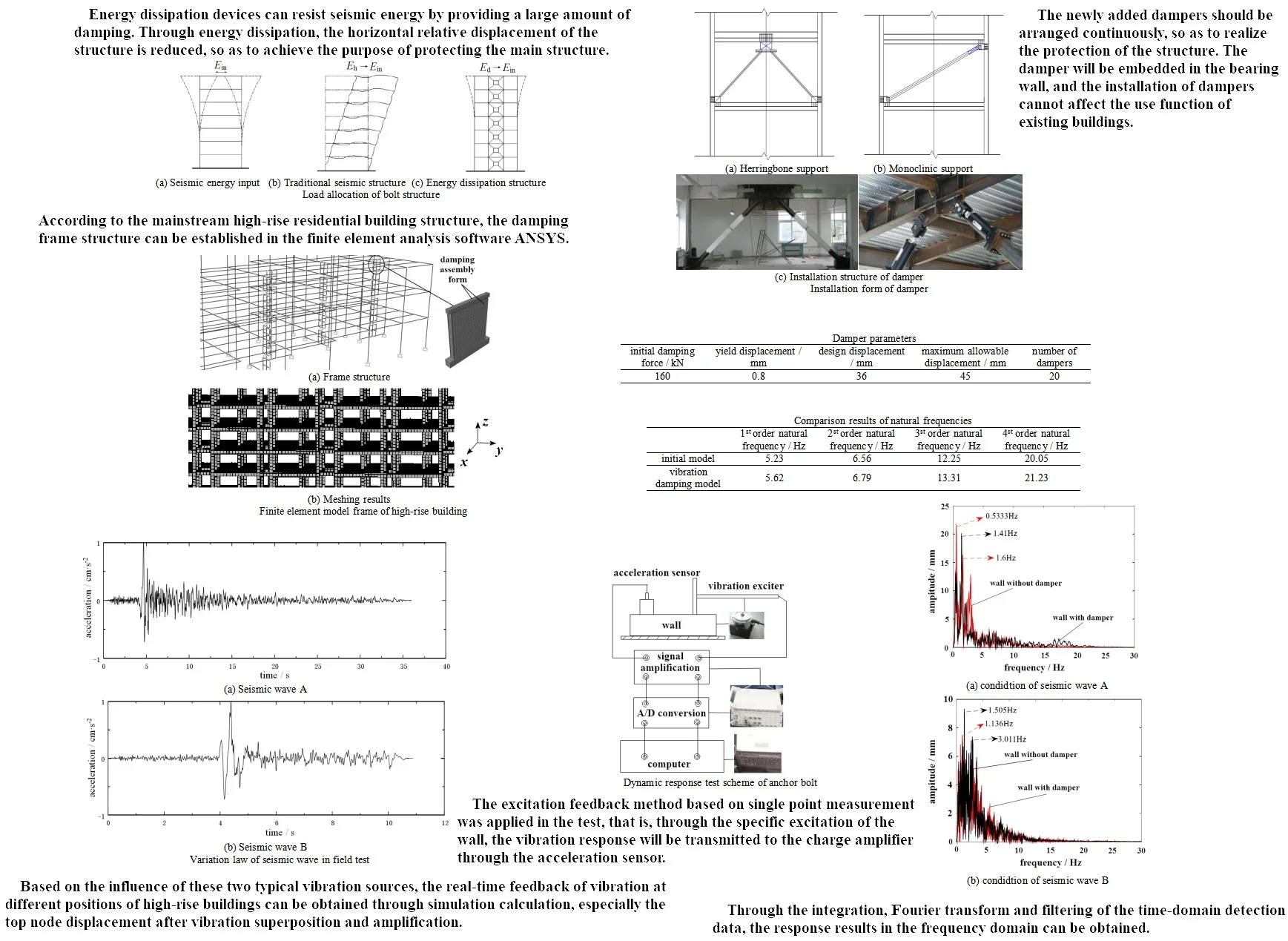
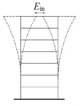
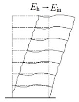
The energy conversion mode of building structure during earthquake is shown in Fig. 1. is total input energy of earthquake, is hysteretic energy consumption of building structure, is energy dissipated by energy dissipation device. It can be seen that energy dissipation devices can resist seismic energy by providing a large amount of damping. Through energy dissipation, the horizontal relative displacement of the structure is reduced, so as to achieve the purpose of protecting the main structure. The wall is mainly damaged by bending and shear. When the wall is subjected to the repeated action of the seismic force, the cracks will gradually blend through the wall. The worst case is that the wall collapses, especially the horizontal cracks along the window will be formed when the wall between windows is sheared under the seismic action.
Fig. 1Load allocation of bolt structure
a) Seismic energy input
b) Traditional seismic structure
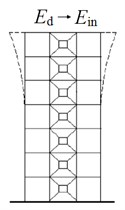
c) Energy dissipation structure
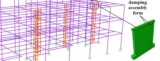
Fig. 2Installation form of damper
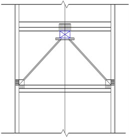
a) Herringbone support
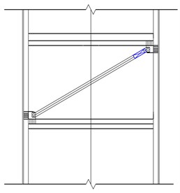
b) Monoclinic support
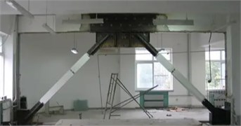
c) Installation structure of damper
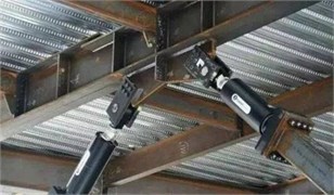
d) Installation structure of damper
According to the transmission characteristics of seismic wave load, the selected anti-seismic part is friction damper. The installation of the damper should follow the principles of uniformity, dispersion and symmetry [11]. Then, the displacement response of the original structure should be checked under the earthquake, and the damper would be installed on the floor with the largest inter story displacement. In practical engineering, when arranging dampers, it should be noted that the number of dampers between each layer should not differ greatly. If there are a large number of dampers on a certain floor, try to install the dampers on the floor with a higher displacement. The newly added dampers should be arranged continuously, so as to realize the protection of the structure. The damper will be embedded in the bearing wall, and the installation of dampers cannot affect the useful function of existing buildings. At present, there are two main installation forms of dampers in construction engineering, as shown in Fig. 2(a) and Fig. 2(b). According to the load conditions, the herringbone installation method is more balanced for energy dissipation, which is suitable for high-rise buildings, as shown in Fig. 2(c, d).
3. Analysis of vibration damping performance
3.1. Model establishment
According to the engineering experience, the floor shear force can be calculated by the mode decomposition response spectrum method of undamped model. Take 10 %-20 % of the floor shear force and divide by the maximum output of the friction damper (100-300 kN), so that the number of dampers can be estimated, as shown in Table 1.
Table 1Damper parameters
Initial damping force / kN | Yield displacement / mm | Design displacement / mm | Maximum allowable displacement / mm | Number of dampers |
160 | 0.8 | 36 | 45 | 20 |
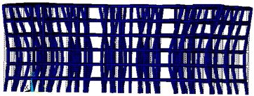
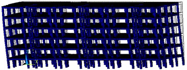
The separation model is to model the blocks and mortar with different material properties according to different elements, and use the interface element to simulate the interaction between them. This model is more similar to the actual brick concrete structure, but its element division is too many, so it is difficult to calculate in the model analysis and the calculation results are difficult to converge. According to the mainstream high-rise residential building structure, the damping frame structure can be established in the finite element analysis software ANSYS, as shown in Fig. 3. The material properties of the model are defined as followed: the strength grade of concrete is C30, and its elastic modulus is 3×10¹⁰ Pa, Poisson’s ratio is 0.2, density is 2400 kg/m3. The longitudinal reinforcement and stirrup are chosen as HRB400 level [12], and its elastic modulus is 2×10¹¹ Pa, Poisson’s ratio is 0.3, density is 7850 kg/m3. The reinforcement ratio of frame column is 0.63 %, that of beam is 0.36 %, and that of floor is 0.5 %. The bottom of the finite element model is rigidly connected with the ground, and the element type is SOLID65. Through grid division, 208692 elements and 862968 nodes are obtained. The horizontal load of the finite element model is controlled by displacement. A reference point is set on the loading beam to facilitate the application of horizontal and vertical loads, so that the members are evenly stressed. The seismic action will be simulated by applying horizontal reciprocating loads, and the vertical loads on the members will be simulated by applying vertical pressure.
3.2. Modal analysis
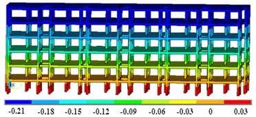
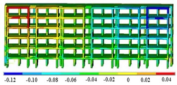
Comparing and analyzing the modal characteristics of the initial model (without damping assembly form) and the vibration damping model (with damping assembly form) can effectively verify the seismic effect. Through finite element simulation and calculation, three modal shapes of these two models can be obtained and shown as in Fig. 4. It can be seen that the damper has little influence on the overall deformation direction, but has a greater influence on the position and relative amplitude. Both of the first-order vibration modes of the building structure are characterized by bending deformation along the direction. Besides, the maximum excitation response of the initial model is located in a large area on both sides, while the vibration reduction model is located at the edge. The main deformation of the second-order modes are bent along the direction and the distribution area is consistent with the first-order vibration mode. The third-order vibration modes are represented by the torsion of the model around the -axis, which is relatively balanced as a whole.
Fig. 3Finite element model frame of high-rise building
a) Frame structure
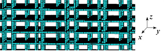
b) Meshing results
Fig. 4Three modal shapes of the model
a) 1st order mode shape of initial model
b) 1st order mode shape of damping model
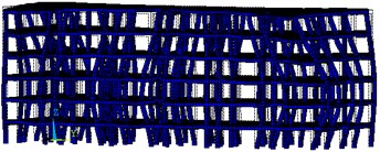
c) 2nd order mode shape of initial model
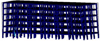
d) 2nd order mode shape of damping model
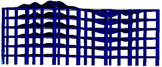
e) 3rd order mode shape of initial model
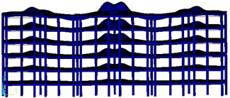
f) 3rd order mode shape of damping model
The local mode shape is the secondary bending deformation along the direction, and the relative vibration on both sides near the roof is larger. In general, the damper can effectively buffer the resonance, reduce the amplitude, and significantly improve the damping effect of the building structure. Compared with the damping earthquake resistance, the traditional reinforcement method needs to increase the wall section and the number of reinforcements, but increases the self-weight of the structure, resulting in the increase of seismic action. At the same time, the efficiency of seismic reinforcement is not satisfactory. The traditional reinforcement method of hard resistance cannot meet the increasing requirements of structural seismic performance.
The comparison results of natural frequencies of different models are shown in Table 2. According to the changing law of natural frequency, it can be seen that the damper has little influence on the natural frequency, but has a great influence on the amplitude range of the excitation response.
Table 2Comparison results of natural frequencies
1st order natural frequency / Hz | 2nd order natural frequency / Hz | 3rd order natural frequency / Hz | 4th order natural frequency / Hz | |
Initial model | 5.23 | 6.56 | 12.25 | 20.05 |
Vibration damping model | 5.62 | 6.79 | 13.31 | 21.23 |
3.3. Analysis of strength response
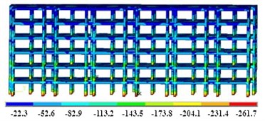
In order to verify the effect of the damper on the strength response, the seismic response dynamics are applied to the initial model and the vibration damping model. For the floor height of the building, the selected seismic wave is EI Centro wave [13]. The duration is 22.8 s, the time interval is 0.02 s, and the maximum acceleration is 3.4 m/s2, which is suitable for class II sites. In the transient analysis module, the maximum displacement response result of the model can be obtained, as shown in Fig. 5.
Fig. 5Analysis results of maximum transient strength response
a) Displacement of initial model (unit of mm)
b) Displacement of vibration damping model (unit of mm)
c) Stress of initial model (unit of MPa)
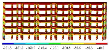
d) Stress of vibration damping model (unit of MPa)
It can be seen that the damper can control the maximum deformation of the building structure within 0.12 mm, which is 42.8 % lower than the initial model. In terms of internal stress control, the damper can reduce the maximum stress by 23.1 %, and the stress distribution of the two models shows an opposite trend. In addition, the damper can buffer the overall deformation, and the difference in deformation is significantly reduced. Due to the cyclic characteristics of the seismic load, the wall model is initially elastic deformation after being loaded in different directions. The stress concentration phenomenon occurs first in the lower right corner of the wall, and the cracks of the wall will appear first at the junction of the wall and the ground. In the process of reverse loading, the change of wall stress state is opposite to that of forwarding loading. In the whole process of wall loading to failure, the wall generally goes through three stages: elastic stage, elastoplastic stage and failure stage. Compared with the initial model, the damper can make the bearing capacity of the wall stronger. Therefore, the path to improve the redundancy of structural seismic performance should not only improve the seismic performance level of the structure and reduce the response of the structure under the design earthquake level, but also include reducing the distribution dispersion of the nonlinear response of the structure.
3.4. Analysis of node support response
Two kinds of seismic wave data measured on site in Sichuan, China on different dates are shown in Fig. 6. The seismic wave is input into the load definition module of the finite element model in the form of data table. Compared with seismic wave B, the effective vibration excitation duration of seismic wave A is longer and the excitation force is larger. Based on the influence of these two typical vibration sources, the real-time feedback of vibration at different positions of high-rise buildings can be obtained through the simulation calculation, especially the top node displacement after vibration superposition and amplification.
Fig. 6Variation law of seismic wave in field test
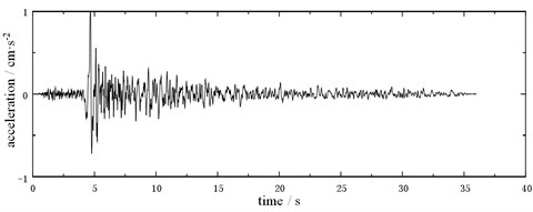
a) Seismic wave A
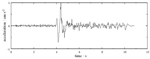
b) Seismic wave B
Through simulation and calculation of finite element transient analysis, the displacement change law at the top central node under different seismic wave conditions can be obtained, as shown in Fig. 7. The damper can effectively reduce the vibration amplitude of the top node of the model, but has little effect on the law and period of displacement change. Under the condition of seismic wave a, the maximum node displacement is 15.2 mm, and the damper can control it within 13.5 mm, reducing 11.2 %. Under the condition of seismic wave B, the damper can reduce the maximum displacement of the joint by 7.6 %. It can be seen that the more intense the vibration is, the more obvious the damping effect of the damper is.
4. Test and analysis of seismic resistance
4.1. Design of experimental test scheme
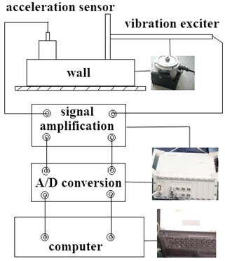
The excitation feedback method based on single point measurement was applied in the test, that is, through the specific excitation of the wall, the vibration response will be transmitted to the charge amplifier through the acceleration sensor [14]. The response signal and excitation signal are transmitted to the charge amplifier for amplification at the same time, and then transmitted to the computer modal analysis software through the A/D converter to calculate the frequency response function for parameter identification. The principle is shown in Fig. 8. The test system has complete dynamic data processing capabilities, including signal conditioning, anti-aliasing filtering, A/D conversion, sampling control and other functions. In addition, the upper computer can adjust the parameters of the exciter to input the seismic waveform as shown in Fig. 6.
Fig. 7Displacement top node under different seismic wave condition
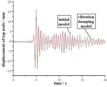
a) Condition of seismic wave A
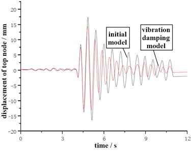
b) Condition of seismic wave B
The exciting force is applied to the bottom of the wall, and the sensor is installed on the top of the wall. Then, the dynamic response difference between the wall with damper and without damper can be compared and analyzed. When the seismic excitation system works, the original data of the selected seismic waves need to be edited by the program first and then input into the computer control system. The system transmits the seismic wave signal to the vibration exciter through USB2.0 communication line, and the table top of the vibration table vibrates the wall horizontally according to the seismic wave signal input in advance. In addition, the amplitude of horizontal vibration can be adjusted by adjusting the gain knob in the software.
Fig. 8Dynamic response test scheme of anchor bolt
4.2. Analysis of seismic resistance effect
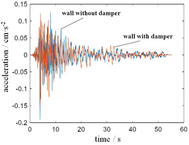
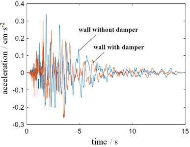
In order to ensure the detection accuracy, the acceleration sensor and measurement system need to be calibrated according to the vibration theory and testing technology. In the process, JX-1A acceleration calibrator and CA-3 integral charge amplifier are used in the data acquisition unit for multiple corrections [15]. Each vibration test is repeated for 5 times, and the average value of the sampling data on the corresponding time step is taken as the analysis result. Under the excitation of two different seismic loads, the vibration response results of the center point at the top of the wall can be detected, as shown in Fig. 9. It can be seen that the damping effect of the damper on seismic waves is very significant, no matter whether the impact type is continuous or intermittent. Under the condition that seismic wave A is used as the excitation source, the maximum vibration acceleration of the measured point is reduced by 26.3 % by the damper, and the stable seismic effect can still be maintained during the impact extension. After the vibration source stops the load input, the wall structure model will continue to vibrate repeatedly for a while due to inertia. Under the condition of seismic wave B with obvious impact in a short time, the damper can control the continuous vibration at a low level, especially in the range of 5-10 s.
Fig. 9Time domain characteristics of vibration response
a) Condition of seismic wave A
b) Condition of seismic wave B
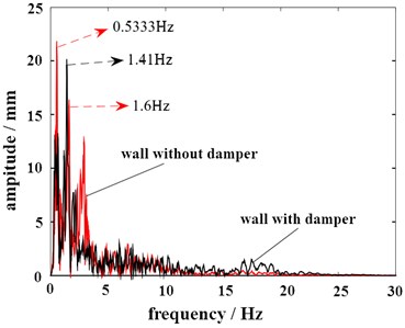
Through the integration, Fourier transform and filtering of the time-domain detection data, the response results in the frequency domain can be obtained, as shown in Fig. 10. It can be seen that the damper will affect the excitation frequency where the maximum vibration amplitude occurs. Under the condition of seismic wave A, the excitation frequencies corresponding to the maximum displacement of the measured point without and with dampers are 0.53 Hz and 1.41 Hz respectively. Under the condition of seismic wave B, it is 1.13 Hz and 1.51 Hz respectively. Because the impact force of seismic wave A is relatively dispersed, the resonance frequency response is more obvious. In terms of amplitude, the damping effect of the damper on the wall is also excellent. The maximum deformation can be reduced by 9.1 % and 18.3 % respectively.
Fig. 10Frequency domain characteristics of vibration response
a) Condition of seismic wave A
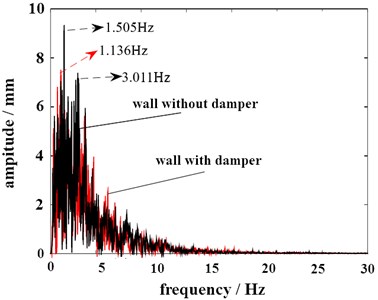
b) Condition of seismic wave B
4.3. Average vibration response of different floors
The height of building has an obvious influence on the vibration performance. Therefore, the influence of damper on vibration response under different floor conditions is studied in this paper. According to the measurement scheme, the change of interlayer displacement angle is obtained, as shown in Fig. 11. It can be seen that there is no nonlinear relationship between floor height and vibration response. Among them, there is an amplitude superposition phenomenon on the 14th floor, which makes the interlayer displacement angle at this position the largest. According to the test and research results, the walls can be further strengthened on the floors where the vibration is superimposed. The transverse vibration is consistent with the longitudinal vibration, which indicates that the damper has a good balance effect. After reinforcement, the ductility, shear and bending capacity of the wall can be greatly improved, and the overall performance of the structure can also be improved. This method is mainly used for the reinforcement of load-bearing masonry walls, but also for the reinforcement of structural columns and ring beams of masonry structures.
Fig. 11Measurement results of interlayer displacement angle under different floors
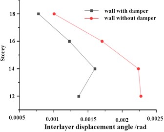
a) The relationship between horizontal interlayer displacement angle and storey
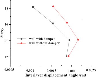
b) The relationship between longitudinal interlayer displacement angle and storey
4.4. Wall reinforcement scheme
The connection position between the horizontal wall and the vertical wall of the building is the weak part of the earthquake resistance. The stress concentration during the earthquake action is complex and serious, and vertical cracks are most likely to occur. The horizontal wall and the wall between windows are most likely to develop oblique cracks. The reinforced cement mortar reinforcement method is one of the most widely used reinforcement methods for brick concrete structures. It can significantly improve the shear and bending bearing capacity of members, and also improve the seismic bearing capacity of masonry structural members. This reinforcement method is convenient for construction and the reinforcement part can be flexible. Local loading at the stress concentration part can improve the bearing capacity and resistance of this part as well as the horizontal seismic resistance of the wall, thus enhancing the safety of the structure. This reinforcement method applies to the reinforcement of the wall to improve the vertical bearing capacity. The reinforcement can be single-sided or double-sided. This reinforcement method is usually used to reinforce both sides of the wall, and has been widely used in practical projects.
5. Conclusions
From the impact of earthquake on high-rise buildings, the limitations and deficiencies of traditional reinforcement technology are more and more obvious. With the emergence of energy dissipation and shock absorption technology, the seismic problem could be well solved. It is known from the research that friction damper has the advantages of good shock absorption effect, short construction period and convenient installation, which will undoubtedly become the mainstream of structural shock absorption in the future. Through the establishment of finite element model, the comparison results of modal, strength and dynamic response of frame structure with and without damper can be effectively obtained. According to the performance comparison results, the seismic effect of the damper on high-rise buildings is effectively verified. The installation of damper can prevent the expansion of structural displacement, which proves that friction damper has good energy dissipation capacity. The vibration response test results of the independent wall show that the vibration reduction scheme is suitable for various types of seismic excitation, including continuous and impact vibration sources. Due to the reciprocating characteristics of seismic waves, simply strengthening the wall from the aspect of hardness improvement will not only increase the production cost, but also will limit the improvement of fatigue life. Under the action of the damper, the interlayer displacement angle is significantly reduced, and the damping rate is about 15 %-30 %. In order to effectively reduce the construction cost, the built-in mode is preferred in the damper arrangement. However, different installation methods and different installation positions can be used to reduce vibration and further optimize the layout of dampers, such as supporting type and setting amplification devices. According to the research conclusion, the friction damper installed in the wall structure can effectively reduce the seismic response of the structure, and will have a broad application field in actual engineering.
References
-
A. Naserpour, M. Fathi, and R. P. Dhakal, “Demountable shear wall with rocking boundary columns for precast concrete buildings in high seismic regions,” Structures, Vol. 41, pp. 1454–1474, Jul. 2022, https://doi.org/10.1016/j.istruc.2022.05.083
-
M. A. Santos-Santiago, S. E. Ruiz, and F. Valenzuela-Beltrán, “Influence of higher modes of vibration on the seismic response of buildings with linear and nonlinear viscous dampers,” Journal of Earthquake Engineering, Vol. 26, No. 8, pp. 3914–3937, Jun. 2022, https://doi.org/10.1080/13632469.2020.1822223
-
T. Sano, K. Shirai, O. Yoshida, and T. Nishikage, “Assessment of a seismic tuned mass damper with friction fail‐safe mechanism for the vibration control of high‐rise buildings,” Structural Control and Health Monitoring, Vol. 28, No. 12, pp. 2861–2866, Dec. 2021, https://doi.org/10.1002/stc.2831
-
J. M. Jara, C. García-Calzada, B. A. Olmos, and G. Martínez, “Seismic response and reliability index of RC weak story buildings on soft soils of Mexico City,” Journal of Building Engineering, Vol. 50, No. 2, p. 104199, Jun. 2022, https://doi.org/10.1016/j.jobe.2022.104199
-
I. Hafner, D. Lazarević, T. Kišiček, and M. Stepinac, “Post-earthquake assessment of a historical masonry building after the Zagreb earthquake-case study,” Buildings, Vol. 12, No. 3, p. 323, Mar. 2022, https://doi.org/10.3390/buildings12030323
-
M. El Hoseny, J. Ma, and M. Josephine, “Effect of embedded basement stories on seismic response of low-rise building frames considering SSI via small shaking table tests,” Sustainability, Vol. 14, No. 3, p. 1275, Jan. 2022, https://doi.org/10.3390/su14031275
-
M. S. Miah, “Vibration mitigation of high-rise buildings via tuned mass damper subjected to dynamic loads,” in IOP Conference Series: Materials Science and Engineering, Vol. 1070, No. 1, p. 012031, Feb. 2021, https://doi.org/10.1088/1757-899x/1070/1/012031
-
Q. Xu, Y. Liu, and Y. X. Song, “Calculation method based on Loess surrounding rock loose circle theory,” (in Chinese), Science, Technology and Engineering, Vol. 21, pp. 10054–10060, 2021.
-
F. Mirshafiei and G. Mcclure, “Modified three-dimensional seismic assessment method for buildings based on ambient vibration tests: extrapolation to higher shaking levels and measuring the dynamic amplification portion of natural torsion,” Earthquake Engineering and Structural Dynamics, Vol. 45, No. 12, pp. 2011–2026, Oct. 2016, https://doi.org/10.1002/eqe.2746
-
L. G. Trujillo-Franco, N. Flores-Morita, H. F. Abundis-Fong, F. Beltran-Carbajal, A. E. Dzul-Lopez, and D. E. Rivera-Arreola, “Oscillation attenuation in a building-like structure by using a flexible vibration absorber,” Mathematics, Vol. 10, No. 3, p. 289, Jan. 2022, https://doi.org/10.3390/math10030289
-
W. Wang, S. Xu, and S. Su, “Study on shear capacity of positive symmetric damper with corrugated web,” (in Chinese), Journal of Hunan University (Natural Science Edition), Vol. 48, No. 11, pp. 112–120, 2021.
-
W. He, “Welding technology of HRB400 prefabricated stirrup for high pier of Niutuoziqing Bridge,” (in Chinese), Welding Technology, Vol. 51, No. 6, pp. 43–46, 2022.
-
Y. Yang and X. Y. Fan, “Study on seismic response of assembled superimposed pipe gallery under EI centro wave,” (in Chinese), Northern Architecture, Vol. 4, No. 3, pp. 23–27, 2019.
-
L. J. Lan and C. T. Liu, “Research on real-time flutter compensation of CNC machine tools based on embedded sensor device,” (in Chinese), Machine Tools and Hydraulics, Vol. 50, No. 13, pp. 37–41, 2022.
-
R. Di Lorenzo et al., “Recommendations for motion correction of infant Fnirs data applicable to multiple data sets and acquisition systems,” NeuroImage, Vol. 200, No. 3, pp. 511–527, Oct. 2019, https://doi.org/10.1016/j.neuroimage.2019.06.056
About this article

The authors have not disclosed any funding.
The datasets generated during and/or analyzed during the current study are available from the corresponding author on reasonable request.
The authors declare that they have no conflict of interest.
