Abstract
Dynamic properties of engine isolators are of significant importance in determining the performance of the isolator and precise prediction of the dynamic behavior at the design stage. Unfortunately, the damping property can not be deduced deterministically from other structural properties because it is highly dependent on dynamic shear properties such as frequency and temperature of material under application. Generally damping properties are determined from experiments conducted on the desired setup. Many times, designers use the damping property data available in literature. Such data may not be recommended for development of predictive models for dynamic behavior. This paper presents a novel method of determination of damping property of the engine isolator. The method is called two-way isolator excitation method (TWIEM). The damping property is determined by excitation of the isolator for active and passive transmissibility. The purpose of this paper is to analyze the vibration isolation by checking the transmissibility ratio for various engine isolators. Sandwiched engine isolators are designed to blend the good properties of different isolation materials to make it more efficient. The experimentation was carried out using three different isolator designs and compared the performance of the isolator on the basis of isolation percentage. Mild steel plates, polymer foam sheets and natural rubber materials are used as Isolator materials. The results show that low damping ratio isolating material is more effective in isolating the vibration source.
1. Introduction
Engine has been the biggest source of vibration in any automobile. Apart from the engine, the other source of vibrations are road irregularities, faults in power trains etc. These vibrations travel through the vehicle structure and enter into the human body, particularly in the driver’s body. Long exposure to these vibrations causes pain in fingers, feet, shoulder, spinal cord etc. The driver feels fatigued and tired during driving. The discomfort to the driver is categorized as whole-body vibration syndrome (WBVS) and hand arm vibration syndrome (HAVS) [1]. There are many international organizations who issued guidelines for the measurement of automobile vibrations such as ISO 2631 or BS 6841[2]. Hand transmitted vibration measurement and evaluation guidelines are given in ISO 5349-1 and ISO 5349-2 [1].
Performance of the isolation system plays a key role in vibration control [3]. Vibration isolation and transmissibility is divided into two types viz. Force transmissibility and motion transmissibility. When isolation system is to be designed to restrict the vibrations from source to the base then this is the case of force transmissibility whereas restricting floor vibrations to enter into a machine is called motion transmissibility. Force and motion transmissibility are also called active and passive isolation respectively [4]. Eq. (1) and (2) show active and passive transmissibility. Eq. (3) shows the percentage of forces or vibrations are isolated by the isolator.
Active transmissibility:
Passive transmissibility:
Isolation percentage:
where is transmitted force, is excitation force, is damping ratio, is ratio of excitation frequency to natural frequency. Similarly, and are vibration amplitudes before and after isolator.
Different types of materials such as visco-elastic, conventional metal, rubber, composites, aluminum, elastomer are used for passive isolation. Whereas magneto-rheological elastomer (MRE), with a controllable (or variable) stiffness and damping, as the semi-active isolator material. The stiffness and damping properties of MRE can be controlled by varying intensity of magnetic field [5]. Out of the isolator materials, a material with high elastic modulus shows good stiffness properties (example steel) whereas some materials show good damping properties due to high bulk modulus. So, the performance of the isolator can be enhanced by blending the stiffness properties of steel and damping properties of rubber to form a sandwiched isolators [6].
Dynamic properties of engine isolators are of significant importance in determining the performance of the isolator and precise prediction of the dynamic behavior at the design stage. Unfortunately, the damping property cannot be deduced deterministically from other structural properties because it is highly dependent on dynamic shear properties such as frequency and temperature of material under application [7]. So, assuming damping properties of the isolator material is not recommended. Therefore, many researchers have used experimental methods of determining the damping properties of the materials [5], [8]. At the same time, some researchers have either assumed damping properties or referred the damping data available in literature [9]-[11]. Damping properties of a material vary with application to application hence use of available data for some other application leads to wrong conclusion. Such available data may be used for development of predictive models for dynamic behavior [7]. This paper presents a novel method of determination of damping property of the engine isolator. The method is called two-way isolator excitation method (TWIEM). The damping property is determined by excitation of the isolator for active and passive transmissibility. Polymer foam and natural rubber are used for making sandwiched isolator along with mild steel. Mild steel is selected for its strength and loss factor for damping purpose. The loss factor and damping ratio of mild steel is in the range of 0.0001 and 0.004 respectively [9]. The viscoelastic behavior of polymer foams is intermediate between the pure elastic solid state and the ideal viscous [12]. Polymer foam material is commonly used as the packaging material for heavy load components. This material is used bymany industries to pack the heavy parts such as transformers, exchanges, turbines extrawhile transporting which provides the strength of the material and its ability to absorb theshocks as it has low density. Elastomeric rubber is another material which has various applications at vibration isolation. The study also compares the performance of sandwiched isolators using mild steel, polymer foam and natural rubber.
2. Two-way isolator excitation method (TWIEM)
Vibration transmissibility ratio is a clear indication of the effectiveness of the engine mount in restricting the vibration to and from the chassis. The transmissibility ratio is a function of physical properties of isolator such as stiffness, natural frequency, and damping coefficient. Out of these isolator physical properties, determination of damping property is very tedious task because damping property depends upon frequency and temperature. Hence a novel experimentation-based method is developed for the determination of damping characteristics of engine isolators. The method is called two-way isolator excitation method (TWIEM). Fig. 1 shows the TWIEM algorithm.
Fig. 1Algorithm of Two-way isolator excitation method (TWIEM)
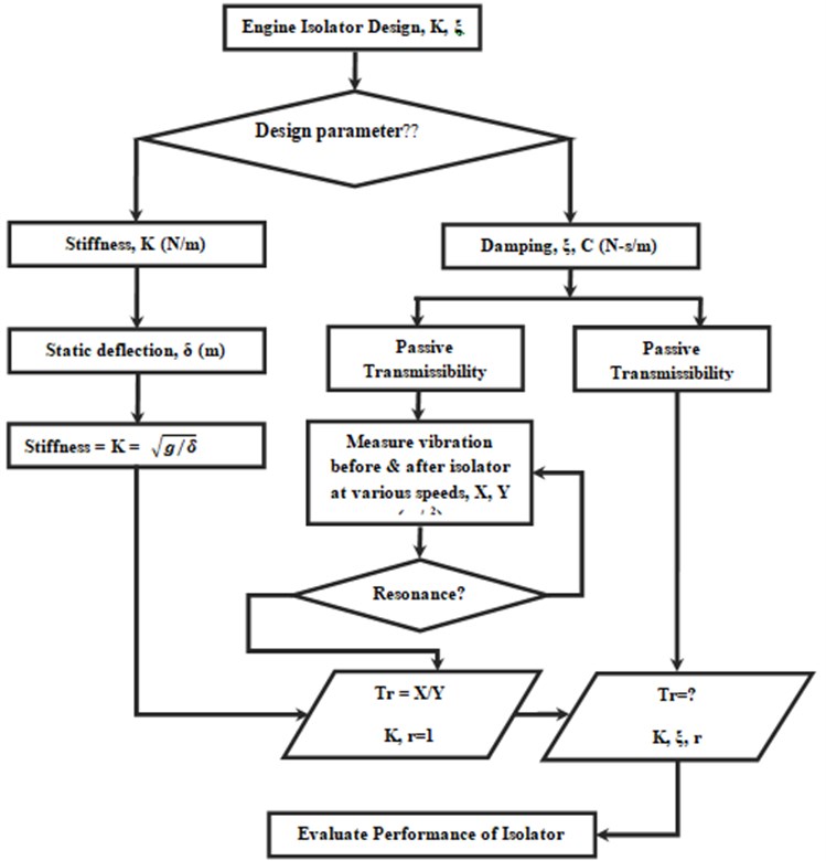
In this method, stiffness of the isolator is calculated using static deflection method. For finding the damping ratio, the engine isolator is excited for passive and active transmissibility. In passive transmissibility, the engine chassis (structure on which the engine is mounted) is excited by the shaking machine at various frequencies to determine resonance frequency. Resonance phenomenon is the one at which amplitude of the chassis would be highest because the excitation frequency matches with natural frequency of the system (frequency ratio, 1). So, the damping ratio of the isolator is calculated by using the vibration acceleration readings before and after isolator, stiffness, and frequency ratio. Now the isolator is excited for active transmissibility to calculate the transmissibility ratio. So, by using the stiffness and damping property of the isolator, the transmissibility ratio is calculated for active transmissibility case. The above TWIEM is repeated for the sandwiched isolator using polymer foam and natural rubber inserted between mild steel plates. The performance of the isolators is compared on the basis of their vibration transfer rate (transmissibility ratio).
3. Experimental setup and instrumentation
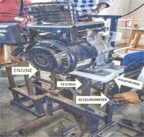
In order to compare the performance of the isolators, three materials are selected to design the three isolators for the comparative study. These three materials are mild steel, polymer foam and natural rubber based on the stiffness and damping properties of these materials. Mild steel is selected for the top and the bottom layer between which the other isolator material (foam & natural rubber) would be induced. Fig. 2 shows sandwiched isolator using polymer foam sheet and mild steel plates. The dimensions of isolator material are given in Table 1 A Briggs& Stratton make, 305cc capacity, air cooled single cylinder gasoline engine weighing 30 kgs is used, which has a peak capacity of generating 20 N.m torque at 3600 rpm. This engine is typically used as a standard engine for SAE BAJA/ Go-kart competitions. The engine mounted on mild steel chassis as shown in Fig. 2.
Table 1Dimensions of isolator material
Material | Length (mm) | Width (mm) | Thickness (mm) |
Mild steel | 320 | 50 | 4 |
Polymer foam | 320 | 50 | 50 |
Natural rubber | 320 | 50 | 8 |
Fig. 2Engine mounted on polymer foam & MS plate sandwiched isolator
A piezo-electric uni-axis accelerometer is used to measure vibration accelerations. The accelerometer is ICP type with built-in amplifier, sensitivity of 100 mV/g, frequency bandwidth 0-20 kHz, range ± 10 g. National instruments make data acquisition set is used which consists of 4-channel 9234 DAQ card and 9171 chassis for computer interface. The maximum sampling frequency of the card is 51.2 kHz USB connected four input channels. This DAQ system is integrated with LabVIEW 15.0 software to analyse vibration signal in time and frequency domain. The accelerometer was then connected to the DAQ and it was interconnected to the computer having Lab-VIEW programming.
4. Experimentation
The engine is mounted on the polymer foam sandwiched isolator to determine the static deflection. The static deflection is used to calculate the stiffness of the isolator. In the same way, stiffness of the other isolators is determined. A series of experimentation is conducted to measure the vibration acceleration amplitude before and after engine mount at various speeds. Vibrations are measured along the vertical axis during experimentation by considering it to be the predominant axis of vibration, and was adopted for the experimental analysis of the composite isolation mounts [4]. Fig. 3 shows the position of accelerometer on the engine base. First of all, the engine is mounted on chassis without any composite isolator sandwiched in between mild steel plates. Now the chassis is excited for passive transmissibility. For this, a shaker machine is used to excite the chassis. Shaker machine excited the chassis at different frequencies. Fig. 4 shows Time & frequency domain plot for vibration acceleration of passive transmissibility before mild steel isolator in case. This process is carried out to determine the resonance frequency of the system. Table 2 shows the vibration acceleration readings before and after isolator for passive transmissibility. The Table 2 also shows the transmissibility ratio at different shaking excitation frequencies.
Fig. 3Accelerometer reading at engine base
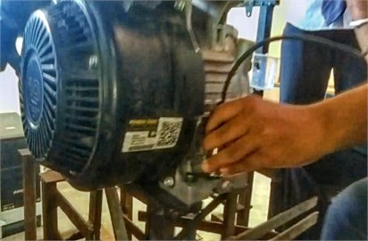
Fig. 4Time and frequency domain plot for vibration acceleration before mild steel isolator for passive transmissibility
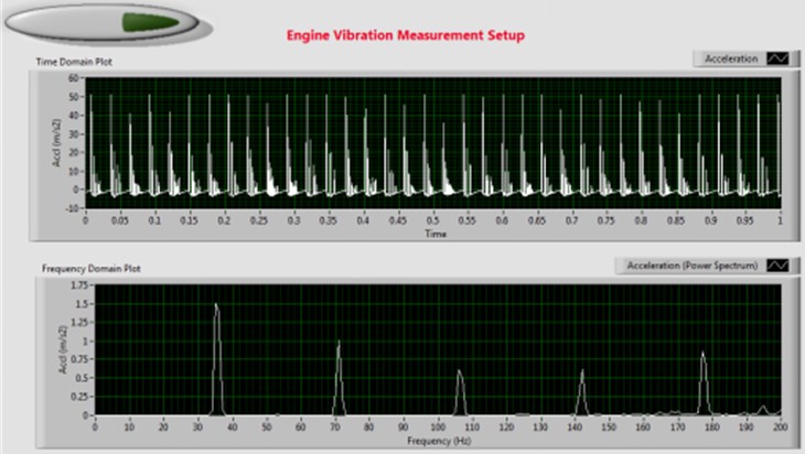
Table 2 shows that the highest acceleration before isolator (at chassis) is 52 m/s2 at 2160 shaking frequency. The transmissibility is also highest at 2160 rpm which indicates that this is point of resonance. The natural frequency of the system is determined to be 36 Hz. So, by using transmissibility ratio at resonance and the stiffness of isolator, damping ratio is calculated. Now the isolator is excited for active transmissibility using the engine. Find the transmissibility ratio for the active transmissibility case to find the percentage of isolation by the isolator. The same method is used to find the isolation percentage of another isolator. The performance of each isolator is analysed by comparing the isolation percentage by the isolators. Table 3 shows the percentage isolation of all the isolator in case of active transmissibility.
Table 2Vibration acceleration before and after mild steel isolator for passive transmissibility
Shaking machine RPM | Acceleration before isolator (m/s2) | Acceleration after isolator (m/s2) | Peak frequency (Hz) | Transmissibility ratio |
1344 | 6.4 | 4.4 | 22 | 1.45 |
1650 | 6.6 | 5.8 | 27 | 1.14 |
1840 | 6.8 | 6.8 | 31 | 1.00 |
1890 | 8.2 | 7.2 | 32 | 1.13 |
1960 | 16 | 8.0 | 33 | 2.00 |
2025 | 31 | 8.5 | 34 | 3.65 |
2045 | 48 | 10 | 34 | 4.80 |
2105 | 42 | 38 | 35 | 1.11 |
2160 | 52 | 12 | 36 | 4.33 |
2260 | 32 | 51 | 39 | 0.63 |
2330 | 15 | 10.2 | 41 | 1.47 |
2500 | 16 | 8 | 42 | 2.00 |
2750 | 28 | 7.5 | 45 | 3.73 |
3700 | 51 | 51 | 62 | 1.00 |
Table 3Transmissibility ratio of mild steel in active transmissibility case
Isolator | RPM | Damping ratio | Damping coefficient | Transmissibility ratio | % Isolation |
Mild Steel | 2160 | 0.83 | 10.23 | 0.57 | 43 |
Polymer foam | 2160 | 0.218 | 2.71 | 0.25 | 75 |
Natural rubber | 2160 | 0.98 | 12.07 | 0.66 | 34 |
5. Conclusions
This paper presents a novel experimental method for the determination of damping property. The present study would also help the designer to select the stiffness and damping ratio for the effective prediction model of vibration isolation. The experimental results show that the engine vibrations are isolated when some visco-elastic material is induced in between the MS plate to form a sandwich pattern. The sandwiched pattern makes a perfect blend of stiffness and damping properties required for any isolator. Out of the three isolators, polymer foam material shows the highest isolation percentage as high as 75 %. So, any material with a damping ratio close to 0.218 and damping coefficient close to 2.71 would greatly isolate vibrations. The study also shows that the isolator can be made more effective by blending the good qualities of different isolating materials for the given application, particularly the applications where forcing frequency varies in a wide range. The study is particularly helpful for the driver's comfort by restricting vibrations from engine, road irregularities to enter into the chassis. This will enhance the performance of the engine and driver.
References
-
A. Fasana and E. Giorcelli, “A vibration absorber for motorcycle handles,” Meccanica, Vol. 45, No. 1, pp. 79–88, Feb. 2010, https://doi.org/10.1007/s11012-009-9229-8
-
X. Zhao and C. Schindler, “Evaluation of whole-body vibration exposure experienced by operators of a compact wheel loader according to ISO 2631-1:1997 and ISO 2631-5:2004,” International Journal of Industrial Ergonomics, Vol. 44, No. 6, pp. 840–850, Nov. 2014, https://doi.org/10.1016/j.ergon.2014.09.006
-
H. Wen, J. Guo, Y. Li, Y. Liu, and K. Zhang, “The transmissibility of a vibration isolation system with ball-screw inerter based on complex mass,” Journal of Low Frequency Noise, Vibration and Active Control, Vol. 37, No. 4, pp. 1097–1108, Dec. 2018, https://doi.org/10.1177/1461348418769650
-
W.-B. Yan, S.-Z. Jiang, Y.-J. Cai, L.-Z. Wen, and Y. Chen, “Experimental study of engine mount system’s vibration characteristics,” 2009 WRI World Congress on Software Engineering, Vol. 3, pp. 43–46, 2009, https://doi.org/10.1109/wcse.2009.259
-
M. Behrooz, J. Sutrisno, X. Wang, R. Fyda, A. Fuchs, and F. Gordaninejad, “A new isolator for vibration control,” in SPIE Smart Structures and Materials + Nondestructive Evaluation and Health Monitoring, Vol. 7977, pp. 351–359, Mar. 2011, https://doi.org/10.1117/12.881871
-
V. B. S. R. Prasad, Dr. G. Venkatarao, and M. Idrees, “Identification of damping characteristics of EPDM-RUBBER with applications to sandwiched beams and considerations to engine mounts for performance evaluation,” Materials Today: Proceedings, Vol. 24, pp. 628–640, 2020, https://doi.org/10.1016/j.matpr.2020.04.317
-
J. Butterworth, J. H. Lee, and B. Davidson, “Experimental determination of modal damping from full scale testing,” in 13th World Conference on Earthquake Engineering, 2004.
-
A. R. Yusoff, B. M. Deros, and D. D. I. Daruis, “Vibration transmissibility on foot during controlling and operating car accelerator pedal,” Applied Mechanics and Materials, Vol. 471, pp. 151–155, Dec. 2013, https://doi.org/10.4028/www.scientific.net/amm.471.151
-
A. M. Ambadas, “Dynamic vibration analysis of an isolator,” in 6th International Conference on Recent Trends in Engineering and Technology, 2018.
-
S. Kumar Battula, P. Rama Murty Raju, and C. H. Ratnam, “Engine isolation angular mount with different types elastomers,” Materials Today: Proceedings, Vol. 5, No. 9, pp. 19555–19564, 2018, https://doi.org/10.1016/j.matpr.2018.06.317
-
E. S. Mohamed, A. A. A. Saad, and S. S. Hassan, “Assessment of vibration and transmissibility behaviour of a rubber engine mount considering vibration tuned modification,” International Journal of Vehicle Noise and Vibration, Vol. 12, No. 1, p. 24, 2016, https://doi.org/10.1504/ijvnv.2016.077471
-
L. Jaouen, A. Renault, and M. Deverge, “Elastic and damping characterizations of acoustical porous materials: Available experimental methods and applications to a melamine foam,” Applied Acoustics, Vol. 69, No. 12, pp. 1129–1140, Dec. 2008, https://doi.org/10.1016/j.apacoust.2007.11.008
About this article

