Abstract
The moment of inertia is an important mass characteristic parameter. It has a direct impact on the trajectory, flight stability, strike accuracy, and service life of the projectile. To meet the measurement of the polar moment of inertia of large projectiles and arrows, this paper uses the vibration compound pendulum method to measure the polar moment of inertia of large projectiles and arrows, deeply analyzes the measurement principle, and designs a polar moment of inertia test equipment. Through the measurement of standard samples, the measurement accuracy of the equipment is tested, and the causes of error are analyzed. The experimental results show that the maximum relative error is less than 0.5 %, and the relative uncertainty is 0.813 %, which meets the requirements of expected technical indicators.
Highlights
- The test equipment of polar moment of inertia is designed
- The polar moment of inertia of a large projectile is measured based on the vibration compound pendulum method
- The causes of errors are analyzed
1. Introduction
The moment of inertia of the projectile relative to the axis is called the polar moment of inertia [1]. The value of the moment of inertia depends on the shape of the object, the mass distribution, and the position of the rotating shaft [2, 3]. The polar moment of inertia is an important structural characteristic that affects the trajectory and flight stability of the projectile and arrow, and also affects the accuracy and service life of the projectile and arrow [4]. Therefore, it is very necessary to master the polar moment of inertia of the projectile and arrow [5]. The dispersion of the polar moment of inertia will affect the dynamic balance angle of the projectile and arrow, which directly leads to the poor shooting accuracy of the projectile and arrow [6]. To accurately predict the flight trajectory of the missile and ensure control accuracy, it is necessary to measure the polar moment of inertia of the missile [7]. Che Ying and others designed and manufactured a light weapon projectile moment of inertia measuring instrument [8] using a double suspension wire torsion pendulum mechanism, which realized the precise measurement of the moment of inertia of small projectiles, but the instrument is not suitable for the measurement of the moment of inertia of large projectiles and arrows. In this paper, the polar moment of inertia test equipment of projectile and arrow is designed by using the vibration compound pendulum method, and the accuracy of the equipment is analyzed, which can meet the needs of the polar moment of inertia test of projectile and arrow.
2. Principle of polar moment of inertia measurement
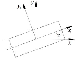
For the projectile with a slender structure [9], the polar moment of inertia is mostly measured by the vibration compound pendulum method. The compound pendulum method is a widely used polar moment of an inertia test method, which has the advantages of high accuracy and high test efficiency [10-12]. The principle of measuring the polar moment of inertia of a large mass projectile and arrow with the vibration compound pendulum method is shown in Fig. 1. When measuring the polar moment of inertia, place the projectile and arrow horizontally on the tooling and clamp it. After the system is stable, apply an external force to make the projectile and arrow torsional vibration freely along its rotation axis. The moment of inertia of the projectile pole can be calculated by measuring the torsional vibration period with a photoelectric sensor.
Fig. 1Schematic diagram of polar moment of inertia of projectile and arrow
According to the law of rotation, the motion equation of the system is shown in Eq. (1):
where is the moment of inertia; is the tensile coefficient of the tension spring; is the damping moment; is the angular displacement. If the influence of damping is ignored, Eq. (1) can be simplified to Eq. (2):
where, ; ; and
where is the no-load moment of inertia of the system, is the moment of inertia of the projectile, is the swing period of the system load, and is a constant, which is determined by the system spring. To determine the values of constants and , it is necessary to measure them with two standard bodies. First, place the standard body 1 on the test equipment. The standard body 1 measures the swing period and obtains Eq. (5) according to Eq. (4):
Then, the standard body 2 is placed on the test equipment. The standard body 2 measures the swing period and obtains Eq. (6) according to Eq. (4):
Eqs. (7) and (8) are calculated from Eqs. (5) and (6):
where: is the theoretical value of the moment of inertia of standard body 1; is the theoretical value of the moment of inertia of standard body 2; is the swing period of the torsion pendulum after adding standard body 1; is the swing period of torsion pendulum after adding standard body 2.
3. Composition of measuring equipment
The projectile pole moment of inertia measuring platform is composed of an equipment base, guide rail, steel belt tensioning mechanism, explosion-proof box, front rolling system, rear rolling system, periodic test device, etc. The main mechanism of the projectile polar moment of inertia measuring platform is shown in Fig. 2.
When measuring the polar moment of inertia of the projectile and arrow, place the projectile and arrow on the front rolling system and the rear rolling system and fix them with clamps. Rotate the handle to pre-tighten the steel belt. Under the drive of the drive motor, the projectile swings at a small angle around its axis. The projectile swings periodically through the release mechanism. The oscillation period of the projectile can be calculated according to the signals collected by the photoelectric sensor. The polar moment of inertia of the projectile can be calculated according to the measurement principle of the vibration compound pendulum method.
Fig. 2Main structure diagram of equipment
4. Error analysis
4.1. Periodic measurement error
According to the measurement principle of the vibration compound pendulum method, the measured value of the polar moment of inertia is proportional to the square of the swing period. Assuming that the measurement error of the period in this system is , the resulting measurement error can be expressed as Eq. (9):
It can be seen from Eq. (9) that the relative error of moment of inertia measurement is only twice the relative error of the time test, which is very small and can be ignored.
4.2. Measurement error caused by an axis position offset
As shown in Fig. 3, the influence of the rotation axis offset on the polar moment of inertia is set as e, and the deviation distance between the rotation axis and the arrow-shaped mandrel is . The polar moment of inertia of the centroidal axis can be expressed as Eq. (10):
The polar moment of inertia of the projectile and the arrow deviating from the rotating axis can be expressed as Eq. (11):
The maximum relative error of polar moment of inertia can be expressed as Eq. (14):
Fig. 3Shaft offset
4.3. Measurement error caused by the tilt of rotating shaft
Due to the installation error and leveling error, the axis of the projectile will have an inclination angle relative to the theoretical axis. As shown in Fig. 4, when the inclination angle is Eq. (15) is obtained according to the rotating shaft formula:
Fig. 4Tilt of rotating shaft
When and are very small, Eq. (15) can be simplified to Eq. (16):
When 0.5°, the influence of the inclination angle on the relative error of the polar moment of inertia of the projectile is not more than 2×10⁻³.
5. Experiment and uncertainty analysis
The standard sample is used to measure the polar moment of inertia. The experimental data are shown in Table 1. The basic Bessel formula [13] is as follows:
where represents the residual of the -th measurement data.
Table 1The measurement results of the pole moment of inertia of the standard sample
Number of experiments | Standard value / kg⋅m2 | Measurements / kg⋅m2 | Relative error / % |
1 | 0.5035 | 0.5042 | 0.1390 |
2 | 0.5045 | 0.1986 | |
3 | 0.5049 | 0.2781 | |
4 | 0.5044 | 0.1787 | |
5 | 0.5040 | 0.0993 | |
6 | 0.5050 | 0.2979 | |
7 | 0.5048 | 0.2582 | |
8 | 0.5055 | 0.3972 | |
9 | 0.5052 | 0.3376 | |
10 | 0.5047 | 0.2383 |
According to Eq. (17), the standard uncertainty of polar moment of inertia measurement is 0.001365 kg⋅m2, the expanded uncertainty is 0.004095 kg⋅m2, and the relative uncertainty is 0.813 %, which meets the accuracy requirements. The experimental results show that the maximum relative error of the polar moment of inertia of the standard sample is 0.3972 %, which meets the requirement that the relative error of the expected technical indicators is less than 0.5 %.
6. Conclusions
In this paper, the vibration-compound pendulum method is used to measure the polar moment of inertia of large missiles, and the measurement principle is deeply analyzed. Based on the vibration-compound pendulum method, a polar moment of inertia test equipment is designed. The equipment has a simple design and manufacture, safe and efficient structure, and can effectively measure the polar moment of inertia of large projectiles and arrows. The causes of measurement error are analyzed, and the measurement accuracy of the equipment is verified by experiments. The maximum relative error is less than 0.5 %, and the relative uncertainty is 0.813 %, which meets the requirements of expected technical indicators.
References
-
P. Chen, H. Wu, and L. Liu, “An improved design of measurement system of polar moment of inertia for missiles,” Journal of Projectiles, Rockets, Missiles and Guidance, Vol. 34, No. 3, pp. 12–14, 2014.
-
Zhao Yan et al., “Identification method for moment of inertia based on torsion pendulum,” Journal of Vibration, Measurement and Diagnosis, Vol. 34, No. 4, pp. 621–624, 2014.
-
C. Liu and W. Hou, “A rotational inertia of measurement error analysis,” Automation and Instrumentation, Vol. 2, pp. 106–107, 2011.
-
Q. Zha et al., “Study on the impact sensitivity of firing factors of self-propelled gun,” Journal of Vibration Engineering, Vol. 30, No. 6, pp. 938–946, 2017.
-
Y. Sun, “Approaches to improve the test accuracy of projectile pole moment of inertia,” Technology and Enterprise, Vol. 2013, No. 21, p. 351, 2013.
-
H. Sun, J. Jin, and Z. Wang, “Impact analysis of revamped shrapnel’s characteristic quantity and projectile dispersion,” Journal of Projectiles, Rockets, Missiles and Guidance, Vol. 34, No. 4, pp. 93–96, 2014.
-
H. Tang et al., “Effect of friction resistance moment on measurement accuracy of polar moment of inertia of projectile by torsion pendulum method,” Journal of Nanjing University of Science and Technology, Vol. 41, No. 5, pp. 569–573, 2017.
-
Y. Che et al., “Development and error analysis of an inspecting system for measuring the rotational inertia of bullets,” Acta Armamentarii, Vol. 2000, No. 1, pp. 87–89, 2000.
-
A. Balakrishna and P. K. Mishra, “Modelling and analysis of static and modal responses of leaf spring used in automobiles,” International Journal of Hydromechatronics, Vol. 4, No. 4, pp. 350–367, 2021.
-
X. Wang et al., “Progress and prospects for the measurement research on the moment of inertia,” Journal of Astronautic Metrology and Measurement, Vol. 39, No. 2, pp. 1–5, 2019.
-
Y. Tanaka, “Active vibration compensator on moving vessel by hydraulic parallel mechanism,” International Journal of Hydromechatronics, Vol. 1, No. 3, pp. 350–359, 2018.
-
I. Rehab et al., “The influence of rolling bearing clearances on diagnostic signatures based on a numerical simulation and experimental evaluation,” International Journal of Hydromechatronics, Vol. 1, No. 1, pp. 16–46, 2018.
-
L. Sun, S. Wang, H. Wang, W. Zhao, J. Li, and L. Dong, “Mass and 3D centroid test and error analysis of small UAV,” Vibroengineering PROCEDIA, Vol. 42, pp. 106–111, May 2022, https://doi.org/10.21595/vp.2022.22616
About this article

The authors would like to thank the national natural science foundation of China U1937201, Science and technology development plan project of Jilin province No. 20200301040RQ and 20210201057GX, Science and technology research project of Jilin Provincial Department of Education No. JJKH20220734KJ.
