Abstract
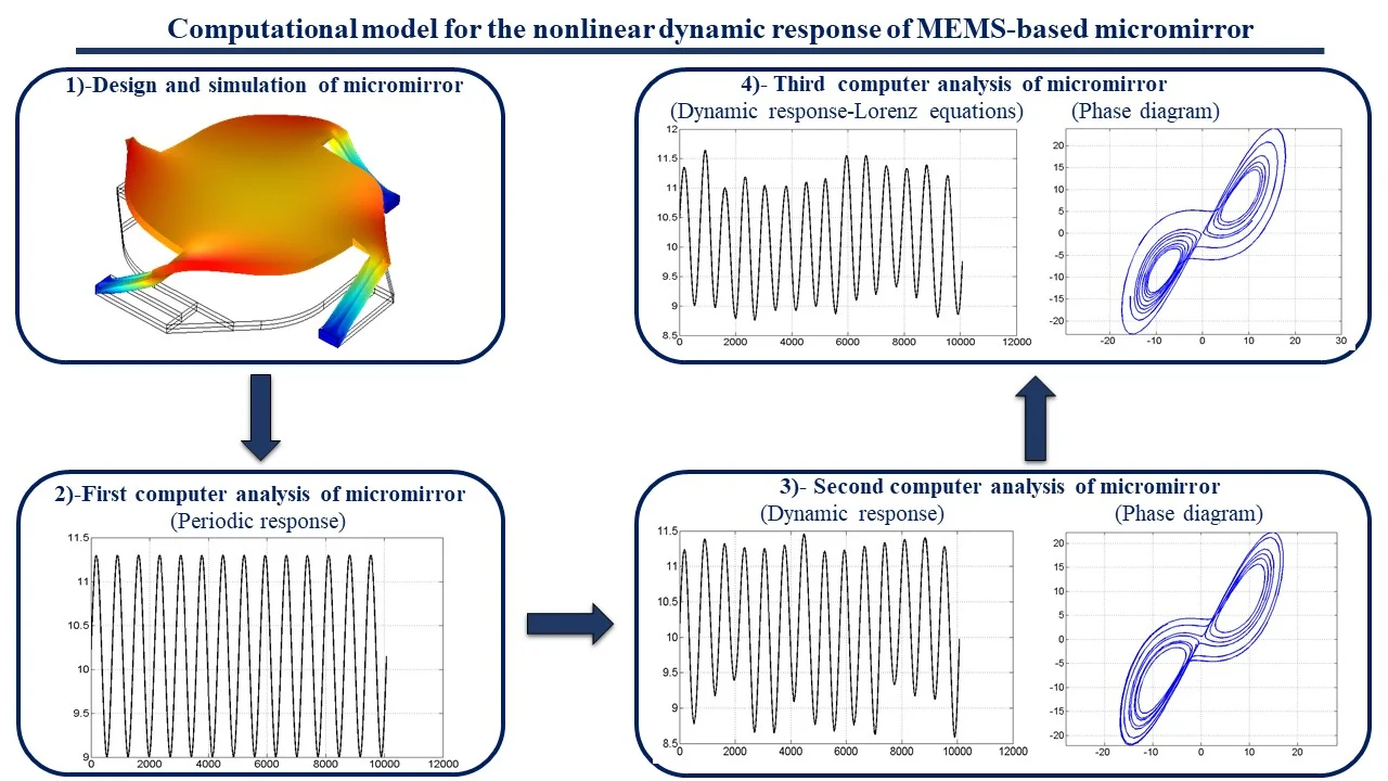
In this study, it is aimed to perform Finite Element Analysis (FEA) of micromirror based on Micro-Electro-Mechanical Systems (MEMS) and to examine the nonlinear and dynamic responses of this system. Micromirror devices are indispensable, especially for optical systems and form the basis of them. In this work, dynamic and nonlinear responses of micromirror with 4 symmetric arms and one reflective surface were investigated. During the design and modeling, it is assumed that the upper and lower layers of the reflective surface have equal tensile and compressive stresses. The analysis of the system was obtained by applying a force of up to 30 GPa Prestressed on the reflective surface. The design and FEA of the micromirror system were made with the Comsol Multiphysics program. The nonlinear response of the analysis was carried out with the MATLAB program. This model, which has the most basic design of micromirror structures used in optical systems, is thought to be a source for a good examination of the nonlinear dynamic model and for understanding more complex structures.
Highlights
- The nonlinear dynamic response of the system was obtained by designing and analyzing the MEMS-based micromirror structure.
- Dynamic analysis of micromirror structures is very important, especially since it is used in optical systems.
- The Micromiror structure usually consists of a reflective surface and different arm designs.
- The nonlinear behavior of the system is obtained by Lorenz Chaos equations.
1. Introduction
The concept of MEMS emerged many decades ago and pioneered the development and advancement of technology. Many studies on Nano Electro Mechanical Systems (NEMS) were started many years ago thanks to MEMS technology [1]-[7]. As MEMS technology and fabrication techniques developed, device diversity began to increase. In particular, studies on micromirror have been closely followed by industry and academia for years. Since micromirror systems have very common usage areas such as optics, projectors, and the defense industry, a lot of work has been done every day [8]-[11]. There are different types of micromirror movement diversity. A general classification is made as electrostatic [12], [13], Electrothermal [14], [15], electromagnetic [16], [17], and Piezoelectric [18]. In this classification, the drive-actuator element and the material used are of great importance. It is also possible to use hybrid structures in complex and complicated systems. Sometimes they can be used with actuator structures to drive the micromirror system. In other words, a micromirror system with both piezoelectric and electrostatic structures can be considered based on the material used.
Nonlinear dynamic response of MEMS micromirror structure was obtained using Invariant Manifolds Calculation [19]. This technique is also known as the nonlinear reduction technique.
Dynamic Response of Electromagnetic MEMS micromirror at vibration time was obtained by constructing a conventional dynamic model [20]. In this study, conventional control systems were applied by modeling the micromirror as mass and spring. Simultaneously, micromirror fabrication and real-time tests were performed. When the obtained data were compared, it was seen that quite good results were obtained.
The nonlinear analysis of Piezoelectric micromirrors was performed using the Harmonic Balance Method [21]. This technique was applied to the system during the finite element analysis. Additionally, micromirror experimental system was established and both methods and experimental data were compared.
Hologram and image acquisition studies have been conducted using Digital Micromirror Devices (DVC) [22]. After controlling the display times of each hologram on the DVC, the problems related to the image acquisition were resolved in this study.
There have been some studies on the effects of the time-averaged holography technique on MEMS [23], [24]. It is seen that these studies are on microcantilever and microsystems.
In this study, the nonlinear dynamic response of the system was obtained by designing and analyzing the MEMS-based micromirror structure, which is widely used in optical systems. When the literature studies were examined, it was seen that similar studies were generally only performed with FEA analyzes and fabrication processes. We believe that this study will contribute to the literature in terms of both finite element analysis and nonlinear response of the micromirror system.
The remainder of this study is organized as follows. In Section 2, material details and design conditions of the micromirror system are explained. In Section 3, all analysis results of the system are given in detail. Finally, in Section 4, the results of this study are given and interpreted.
2. Materials and methods
In order to obtain the nonlinear and dynamic responses of the system, the design conditions and simulation details of micromirror should be known. The geometry, mesh conditions and material of the system are pre-designed so that FEA can be performed smoothly. After all the simulation details were determined, analyzes were made in the Comsol Multiphysics program.
2.1. Design of the micromirror
The design and meshing of the micromirror system were made in the Comsol Multiphysics program. The design and overall dimensions of the system are shown in Fig. 1(a). The length of the reflective surface of the system is 1200 µm, and the length of each symmetrical arm is 400 µm. The mesh structure of the system is shown in Fig. 1(b). The physics-controlled mesh of the Comsol program was applied to the system. Mesh values of the designed system are given in Table 1.
Fig. 1Design and mesh of micromirror
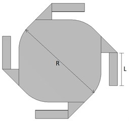
a) Design and dimension
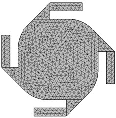
b) Mesh of micromirror
Table 1Mesh statistics of design
Description | Value |
Minimum element quality | 0.08741 |
Average element quality | 0.4642 |
Tetrahedron | 8501 |
Triangle | 4664 |
Edge element | 628 |
Vertex element | 96 |
2.2. Material detail
In order to analyze the system, the appropriate material to be used must be selected. In this study, four symmetrical arms were used. Ag-Silver material is used for these arm materials. Structural steel material was used for the reflective surface. Material selection was carried out using the Comsol Multiphysics program library.
3. Results and discussion
The FEA, nonlinearity and dynamic response of the system is examined in this section. In order to perform nonlinear and dynamic analysis of the system, first of all, micromiror’s design and FEA were obtained using the Comsol Multiphysics program. Because of the simulation, the displacement effects of the prestressed pressure acting as the entrance to the system on the reflecting surface of the micromirror were investigated. It has been discussed that the prestress acting on the system makes the system nonlinear after a certain value. The nonlinear regions where the prestressed values affect the system has been examined in detail. After all, these analysis, the computer calculations of the micromirror and the phase diagram were made and the dynamic response result of the system was obtained.
3.1. Simulation results
A simulation graph of micromirror is given in Fig. 2(a). According to the simulation results, the maximum displacement on the system was at A and C points and was measured as 250 µm (Since the system was designed symmetrically, these points had to be equal). The minimum displacement is at point B, which is marked as the midpoint of the reflective surface, and is approximately 205 µm. These values were obtained when 30Gpa prestress was provided as an input to the system. The length between points A and C was measured as approximately 1200 µm. In Fig. 2(b), the maximum and minimum displacement curves are given according to the A and C sections.
Fig. 2Simulation results of micromirror
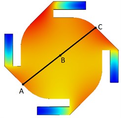
a) Simulation section view
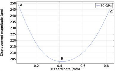
b) Displacement - Prestressed result
3.2. Nonlinear respond results
Because of the analysis made with Comsol, the prestress and displacement graph are obtained in Fig. 3(a). The prestress-displacement relationship is linear in Region I. In other words, it has been understood that the micromirror gives a linear response when Prestress is applied to the system up to 10 GPa. However, the system does not give a linear response in Regions II and III. (As the deformations in the material affect the analysis results, the analyzes in this study were not performed after 35 GPa. Also, all analyzes were performed between 1-30 GPa).
The computer analysis of the system in Region I is given in Fig. 3(b). In this region, the response of the system is linear. In other words, the micromirror displaces a maximum of 11.3 µm and a minimum of 9 µm at each GPa prestress applied to the system. It is understood that the system response is periodic.
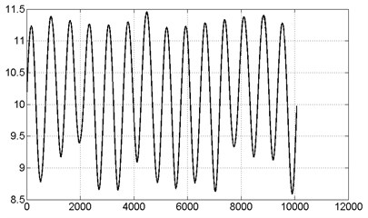
The computer analysis of the system in Region II is given in Fig. 3(c). The response of the system in this region is not linear. In this region, the maximum and minimum values of the signal at the input of the system are 10.26 and 8.101 µm, respectively. In other words, it is seen that the difference value at the input of the system is 2.16 µm. The maximum and minimum values of the signal at the output of the system are 8.31 and 6.25 µm, respectively. The difference value at the output of the system is also 2.05 um.
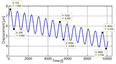
The computer analysis of the system in Region III is given in Fig. 3(d). The system also shows nonlinear behavior in this region. In this region, the maximum and minimum values of the signal at the input of the system are 7.65 and 5.69 µm, respectively. In other words, it is seen that the difference value at the input of the system is 1.95 µm. The maximum and minimum values of the signal at the output of the system are 5.33 and 3.73 µm, respectively. The difference value at the output of the system is 1.6 µm.
Fig. 3Nonlinear respond results
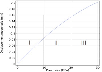
a) Displacement-Prestressed analysis of micromirror
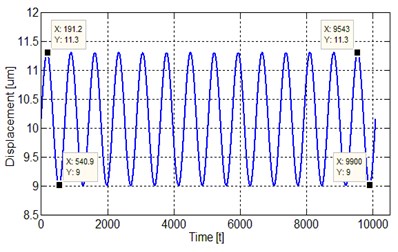
b) Linear response of the system in Region I (0-10 GPa)
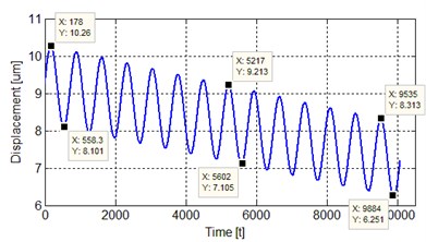
c) Nonlinear response of the system in Region II (10-20 GPa)
d) Nonlinear response of the system in Region III (20-30 GPa)
3.3. Dynamic response results
The displacement curve for each prestress applied to the system is shown in Fig. 4. As shown in the figure, the system gives a periodic response. The dynamic behavior of the system can be obtained by applying Lorenz equations [25] to this region where the system shows a periodic behavior.
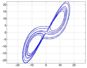
Lorenz chaos equations were applied to the region where the system in Fig. 4, gives a periodic response. Because of the equation was applied with the MATLAB program, the graphics in Fig. 5 were obtained. Fig. 5(a) shows the dynamic response of the system and is the second computer analysis of the system. Fig. 5(b) shows the phase diagram of the system.
The third computer analysis of the system is shown in Fig. 6. The chaotic behavior of the system is provided by the Lorenz chaos equations. Here, it is seen that the system is non-periodic and exhibits a chaotic behavior. Fig. 6(a) shows the dynamic response of the system. Fig. 6(b) shows the phase diagram of the system.
Fig. 4First computer analysis of Micro-mirror
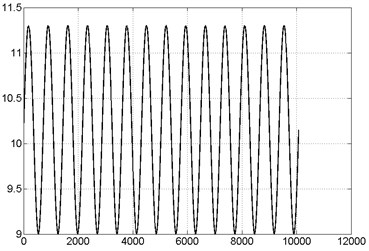
Fig. 5Second computer analysis of micromirror
a) Second computer analysis
b) Phase diagram
Fig. 6Third computer analysis of micromirror
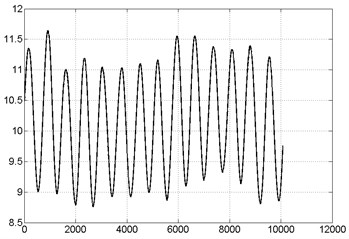
a) Third computer analysis
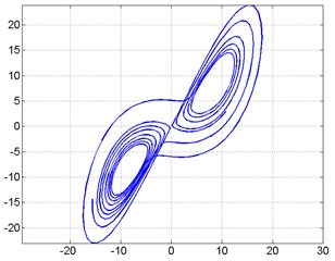
b) Phase diagram
4. Conclusions
In this study, the prestressed was applied to the system and the displacement analysis was performed. In addition, that, nonlinear and dynamic analyzes were performed on the micromirror model for the first time. The analysis was obtained with the development of the micro mirror model in the Comsol library.
Maximum and minimum displacement values were obtained by simulating the system. Prestressed is applied up to 30 GPa as input to the system. It has been observed that the system exhibits non-linear behavior after 10 GPa. After all these data were obtained, the dynamic behavior of the system was obtained by applying Lorenz equations to the system.
We think that this study, which explains the modeling of basic micromirror devices, which are indispensable for optical systems, will be an important resource for models with complex systems and will fill the gap in the current literature in this respect. Time-Averaged Holography and Chaotic Visual Cryptography (CVC) techniques can also be successful on the micromirror system and we continue to work on this issue.
References
-
M. Gad-El-Hak, The MEMS handbook. Florida, USA: CRC Press, 2001.
-
J. W. Judy, “Microelectromechanical systems (MEMS): fabrication, design and applications,” Smart Materials and Structures, Vol. 10, No. 6, pp. 1115–1134, Dec. 2001, https://doi.org/10.1088/0964-1726/10/6/301
-
M. Gad-El-Hak, MEMS: Design and Fabrication. Florida, USA: CRC Press, 2005.
-
G. K. Fedder, Simulation of Microelectromechanical Systems. Berkeley, USA: University of California, 1994.
-
N. Maluf and K. Williams, An Introduction to Microelectromechanical Systems Engineering. Artech House, 2004.
-
M. Mehregany, “Microelectromechanical systems,” IEEE Circuits and Devices Magazine, Vol. 9, No. 4, pp. 14–22, Jul. 1993, https://doi.org/10.1109/101.250229
-
M. Huff, “MEMS fabrication,” Sensor Review, Vol. 22, No. 1, pp. 18–33, Mar. 2002, https://doi.org/10.1108/02602280210697087
-
D. Torres, L. Starman, H. Hall, J. Pastrana, and S. Dooley, “Design, simulation, fabrication, and characterization of an electrothermal tip-tilt-piston large angle micromirror for high fill factor segmented optical arrays,” Micromachines, Vol. 12, No. 4, p. 419, Apr. 2021, https://doi.org/10.3390/mi12040419
-
L. J. Hornbeck, “Digital Light Processing for high-brightness high-resolution applications,” in Electronic Imaging ’97, Vol. 3013, No. 1, pp. 27–40, May 1997, https://doi.org/10.1117/12.273880
-
D. Wang, L. Thomas, S. Koppal, Y. Ding, and H. Xie, “A low-voltage, low-current, digital-driven MEMS mirror for low-power LiDAR,” IEEE Sensors Letters, Vol. 4, No. 8, pp. 1–4, Aug. 2020, https://doi.org/10.1109/lsens.2020.3006813
-
H. Hillmer et al., “Optical MEMS-based micromirror arrays for active light steering in smart windows,” Japanese Journal of Applied Physics, Vol. 57, No. 8S2, p. 08PA07, Aug. 2018, https://doi.org/10.7567/jjap.57.08pa07
-
F. Hu, J. Yao, C. Qiu, and H. Ren, “A MEMS micromirror driven by electrostatic force,” Journal of Electrostatics, Vol. 68, No. 3, pp. 237–242, Jun. 2010, https://doi.org/10.1016/j.elstat.2010.01.005
-
Y. Cao, P. Wang, J. Li, and H. Xie, “Temperature stability study of resonant angular scanning micromirrors with electrostatic comb-drive actuators,” Sensors and Actuators A: Physical, Vol. 318, p. 112525, Feb. 2021, https://doi.org/10.1016/j.sna.2020.112525
-
Y. Tang, J. Li, L. Xu, J.-B. Lee, and H. Xie, “Review of electrothermal micromirrors,” Micromachines, Vol. 13, No. 3, p. 429, Mar. 2022, https://doi.org/10.3390/mi13030429
-
Y. Tang, J. Li, J.-B. Lee, H. Xie, and L. Xu, “An approach for achieving uniform temperature distribution on the bimorphs of electrothermal micromirrors,” Sensors and Actuators A: Physical, Vol. 342, p. 113632, Aug. 2022, https://doi.org/10.1016/j.sna.2022.113632
-
W. Sun and Y. Tan, “Model guided extremum seeking control of electromagnetic micromirrors,” Scientific Reports, Vol. 11, No. 1, pp. 1–15, Dec. 2021, https://doi.org/10.1038/s41598-021-97098-6
-
Y. Hua, S. Wang, B. Li, G. Bai, and P. Zhang, “Dynamic modeling and anti-disturbing control of an electromagnetic MEMS torsional micromirror considering external vibrations in vehicular LiDAR,” Micromachines, Vol. 12, No. 1, p. 69, Jan. 2021, https://doi.org/10.3390/mi12010069
-
M. Zamprogno, L. Molinari, and A. Barbieri, “Efficient driver and high accuracy sense ASICs for piezoelectric micro-mirrors,” in MOEMS and Miniaturized Systems XX, Vol. 11697, pp. 116–126, Mar. 2021, https://doi.org/10.1117/12.2577150
-
A. Opreni et al., “Fast and accurate predictions of mems micromirrors nonlinear dynamic response using direct computation of invariant manifolds,” in IEEE 35th International Conference on Micro Electro Mechanical Systems Conference (MEMS), pp. 491–494, Jan. 2022, https://doi.org/10.1109/mems51670.2022.9699545
-
X.-Y. Fang, X.-Y. Li, K.-M. Hu, G. Yan, J.-H. Wu, and W.-M. Zhang, “Destructive reliability analysis of electromagnetic MEMS micromirror under vibration environment,” IEEE Journal of Selected Topics in Quantum Electronics, Vol. 28, No. 5, pp. 1–8, Sep. 2022, https://doi.org/10.1109/jstqe.2021.3124140
-
A. Opreni, N. Boni, R. Carminati, and A. Frangi, “Analysis of the nonlinear response of piezo-micromirrors with the harmonic balance method,” Actuators, Vol. 10, No. 2, p. 21, Jan. 2021, https://doi.org/10.3390/act10020021
-
T. Takahashi, T. Shimobaba, T. Kakue, and T. Ito, “Time-division color holographic projection in large size using a digital micromirror device,” Applied Sciences, Vol. 11, No. 14, p. 6277, Jul. 2021, https://doi.org/10.3390/app11146277
-
P. Palevicius, M. Ragulskis, A. Palevicius, and V. Ostasevicius, “Applicability of time-averaged holography for micro-electro-mechanical system performing non-linear oscillations,” Sensors, Vol. 14, No. 1, pp. 1805–1821, Jan. 2014, https://doi.org/10.3390/s140101805
-
P. Palevicius, L. Saunoriene, M. Cao, and M. Ragulskis, “Time-averaged computer generated holography for the estimation of torsional amplitudes of oscillating microdevices,” Optics Communications, Vol. 439, pp. 260–269, May 2019, https://doi.org/10.1016/j.optcom.2019.01.072
-
K. Mischaikow and M. Mrozek, “Chaos in the Lorenz equations: a computer-assisted proof,” Bulletin of the American Mathematical Society, Vol. 32, No. 1, pp. 66–72, Jan. 1995, https://doi.org/10.1090/s0273-0979-1995-00558-6
About this article

This study was supported by The Scientific and Technological Research Council of Turkey (TUBITAK) within the scope of the Scientist Support Program.
