Abstract
In this study, the influences of the squeeze-film damping effect on the dynamic behavior of the microelectromechanical electrostatic actuators are investigated by the hybrid numerical scheme comprising the differential transformation method and the finite difference method. There are two types of actuators which including the circular micro-plate and the clamped-clamped micro-beam, relatively. The analyses take account of the axial stress effect, the residual stress and the fringing field effect within the micro actuators and explore the dynamic response of the plate/beam as a function of the magnitude of the AC driving voltage. The effectiveness of a combined DC/AC loading scheme in driving the micro actuators are examined. It is shown that the use of an AC actuating voltage in addition to the DC driving voltage provides an effective means of tuning the dynamic response of the micro actuators. Therefore, the results show that the hybrid method provides an accurate and computationally-efficient means of analyzing the nonlinear behavior of the micro-beam structures used in many of today’s MEMS-based actuator systems.
1. Introduction
Micro-electro-mechanical systems (MEMS) devices have applications in many engineering fields such as communications [1], automotive industry [2] and chemical [3], and so on. Such devices are generally actuated using either electrostatic [4], electromagnetic [5], thermal or piezoelectric [6] techniques. Of these various techniques, electrostatic actuation schemes are the most commonly employed due to their fast response, low power consumption, reliability and their batch fabrications [7]. Actually, in the electrostatic actuation of a micro-structure system, the electrostatic force is produced from the voltages of two electrodes. If the electrostatic force is greater than the elastic restoring force of the micro-structure system, this represents an unstable phenomenon, and the two electrodes attract and come into contact with each other suddenly [8]. The critical value of the voltage is defined as the pull-in voltage, which has a tremendous influence on the electrostatic device. For example, the electrostatic device is regarded as a digital actuator when the operation voltage is greater than the pull-in voltage and the upper electrode can be attracted to the fixed bottom electrode very quickly; therefore, the pull-in voltage limits the operation range of the actuator. The pull-in behavior phenomenon, however, can be used in the design of such components as switches and relays. Hence, the pull-in voltage is a very important parameter in the design of microelectromechanical devices.
Accordingly, many researchers have proposed more sophisticated techniques for modeling the nonlinear behavior of electrostatic actuators which including the micro-plate and the micro-beam. Chao et al. [9] proposed a novel computational method for predicting the static pull-in event between two micro-plates actuated by a distributed electrostatic force. Chen et al. [10] used a hybrid differential transformation / finite difference method to analyze the nonlinear dynamic behavior of a clamped-clamped micro-beam in the absence of a squeeze-film damping effect. Younis et al. [11] presented a continuous reduced-order model for predicting the static pull-in voltage and position of electrically actuated MEMS micro-beams. Taking into account geometric nonlinearity and residual stresses, Vogl and Nayfeh [12] presented an analytical continuous reduced-order model (macromodel) for an electrically actuated clamped circular plate with a uniform residual biaxial plane stress consideration for actuated, and than using a Galerkin approach method to discretize the microstructure.
To increase the actuation efficiency and detection sensitivity of MEMS-based devices, the separation distance between the two electrodes must be minimized and the overlapping area between them maximized. Under such conditions, a squeeze-film damping effect occurs between the two electrodes as the upper electrode deforms [13]. The Squeeze-film damping can be modeled using the Reynolds equation, which is derived from the Navier–Stokes equations and the continuity equation. The main assumption is that the gas in the gap can be treated as a continuum. The validity of this assumption depends on the so-called Knudsen number () which defined as the ratio of the mean free path of the air particals to the film thickness. Based on the Knudsen number, the air flows can be divided into four regimes: continuum flow when 0.01, slip flow when 0.01 0.1, transitional flow when 0.1 10 and free molecular flow when 10. Krylov and Maimon [14] have studied the transient dynamics of an electrically actuated micro-beam considering the electrostatic forces, squeeze-film damping, and rotational inertia of a mass carried by the micro-beam.
Dynamic analysis currently MEMS devices are being positively developed for various widely applications of industries. Younis [15] examined the dynamic behavior of micro-beams subject to combined DC / AC loading and derived analytical expressions for the micro-beam motion under primary resonance conditions. Chen et al. [10] demonstrated that the hybrid differential transformation and finite difference method provides a precise and computationally-efficient means of analyzing the nonlinear dynamic behavior of fixed-fixed micro-beams.
In the present study, the hybrid numerical scheme comprising the differential transformation method and the finite difference method is applied to analyze the dynamic behavior of the circular micro-plate / the clamped-clamped micro-beam actuated by pure DC or combined DC / AC loading schemes. The analyses take account of the electrostatic coupling effect, the fringing field effect, the residual stress, the nonlinear electrostatic force, the axial stress effect and squeeze-film damping effect.
2. Differential transformation theory
Differential transformation theory was originally proposed by Zhou [16] in 1986 as a means of solving linear and nonlinear initial value problems in the circuit analysis field. However, later researchers extended its use to the analysis of the mechanical engineering domain [10, 13, 17]. The basic principles of the differential transformation method are introduced below. If is an analyzable function in time domain , a definition of the differential transformation of at in the domain is:
where belongs to the set of non-negative integers denoted as the domain, is the transformed function in the transformation domain, otherwise called the spectrum of at in the domain, is the weighting factor, and is regarded as a kernel corresponding to . Both and are non-zero and is an analyzable function in time domain . Therefore, the differential inverse transformation of can be described as:
If and , where is the time interval. Let ; Eq. (1) then becomes:
The differential inverse transformation of can then be expressed as below by Eq. (2):
Substituting Eq. (3) into Eq. (4) gives:
Eq. (5) can be derived by Taylor series expansion. Therefore, the main basic operation properties of the differential transform are listed below:
a) Linearity operation:
where denotes the differential transform and and can be any real number.
b) Differential operation:
where denotes the differential transform and n is the order of differentiation [10, 13, 17].
3. Modeling of microelectromechanical electrostatic actuators
3.1. Modeling of clamped-clamped micro-beam
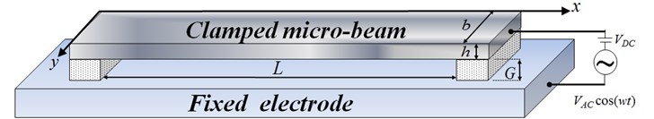
The analysis performed in this study considers the clamped-clamped micro-beam shown in Fig. 1. As shown, the upper plate is actuated by a driving voltage , where is the DC polarization voltage, is the magnitude of AC voltage, and is the excitation frequency. In deriving the governing equation of the clamped-clamped micro-beam which considers the fringing field effect, the residual stress and the squeeze-film damping effect within the beam. The corresponding governing equation is therefore given by [13]:
Regarding the right-hand side of Eq. (1), represents the excitation force per unit beam length and is given by:
where , and denote the permittivity of free space, the width of the micro-beam and the initial gap size between the upper and lower electrodes, respectively. Moreover, is the effective beam material modulus. For the case of a wide micro-beam (i.e., ), is equal to the plate modulus, i.e. , where is the Poisson ratio and is the beam thickness. Conversely, for a narrow beam, is equal to the Young’s modulus, . In Eq. (8), denotes the moment of inertia of the micro-beam, is a constant denoting the residual force acting on the beam and is the transverse displacement of the beam and varies as a function of both the longitudinal position and the time , i.e.,. Note that the residual force is given by , where is the residual stress and has the form of , in which is the biaxial residual stress.
Finally, denotes the force acting on the beam due to the squeeze-film damping effect and is given by:
where is the absolute pressure in the air gap and is the ambient pressure. The net pressure can be expressed as . The squeeze-film damping effect in Fig. 1 can be described by the nonlinear Reynolds equation:
Note that and represent the variable distance between the two electrodes (), the density of the air in the air gap, and the effective viscosity of the air in the air gap, respectively.
Fig. 1Schematic illustration of the clamped-clamped micro-beam
3.2. Modeling of circular micro-plate
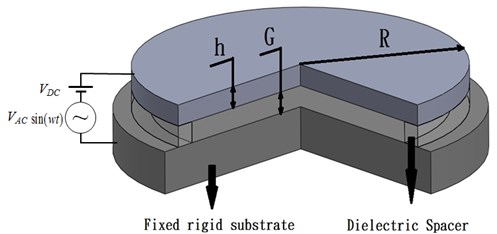
In deriving the governing equation of motion for the circular micro-plate shown in Fig. 2, the study considers both the residual stress within the plate and the squeeze-film damping effect between the two plates. The governing equation is therefore given as [8]:
where , and are represented the permittivity of free space, the thickness of the circular micro-plate, and the initial gap height between the upper and lower plates, respectively. In addition, is the voltage between the two plates, (i.e., ), is the density of the micro circular plate, and is the transverse deflection of the circular micro-plate at a distance from the center of the plate. In other words, the symmetry transverse deflection of micro circular plate is irrelevant to polar coordinate . Finally, is the residual stress within the plate, is the net pressure within the air gap and is the flexural rigidity of the plate, i.e.:
where and are the Poisson ratio and Young’s modulus of the upper circular plate, respectively. The squeeze-film damping effect within the air gap is modeled using the linearized compressible gas-film Reynolds equation [13], which has the form:
where and represent the variable distance between the two electrodes (i.e., ) and the effective viscosity of the air in the air gap, respectively. The net pressure in the air gap can be expressed as , where is the absolute pressure in the gap and is the ambient pressure.
Fig. 2Schematic illustration of the circular micro-plate
4. Numerical results and discussion
4.1. Clamped-clamped micro-beam
In this section, the validity of the proposed hybrid numerical scheme was demonstrated by comparing the predicted value of the pull-in voltage with that obtained using different scheme in the literature and the computations were performed using MATLAB. Note that in performing the analysis, the material and geometry properties of the micro-beam were assigned the values given in Table 1. In performing the comparison, as shown in Table 2, it is seen that the pull-in voltage calculated using the proposed method is just 1.4 % lower than that presented in the literature.
Table 1Material and geometry parameters of the clamped-clamped micro-beam
Parameters / Symbol / Unit | Value |
Young's modulus () (GPa) | 151 |
Poisson’s Ratio () | 0.3 |
Density () (kg/m3) | 2332 |
Thickness of circular plate () (μm) | 1.5 |
Initial gap () (μm) | 1.18 |
Length of beam () (μm) | 210 |
Biaxial residual stress () (MPa) | 6 |
Table 2Comparison of present analytical results and literature results for pull-in voltages
Analytical results | Deviation | ||
Hybrid numerical scheme | DQM [18] | (%) | |
Pull-in Voltage (V) | 27.7 | 28.1 | 1.4 |
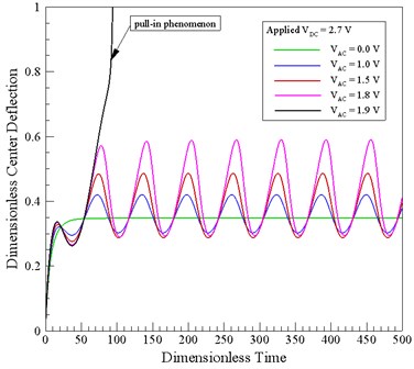
Fig. 3 shows the variation over time of the center-point deflection of the micro-beam for a constant DC voltage of 27 V and AC voltages in the range of 0-1.9 V. It is seen that the center-point deflection increases nonlinearly with an increasing AC voltage due to the nonlinear of the electrostatic coupling effect. Furthermore, it is observed that for a dimensionless time of less than 60, the DC voltage is unstable with a smaller deflection of the center point. In addition, the results show that for an AC voltage of 1.8 V, the micro-beam oscillates in a stable manner about the equilibrium deflection point. However, when the AC voltage is increased to 1.9 V, the micro-beam collapses and makes transient contact with the lower electrode.
Fig. 3Variation of dimensionless center-point displacement over time for different AC voltages
4.2. Circular micro-plate
Fig. 4 illustrates the variation of the center-point deflection of the micro-plate over time as a function of the AC voltage. Note that in performing the analysis, the basic material and geometry properties of the micro-plate is assigned in accordance with the data presented in Table 3. The results show that as the AC voltage increases, the center-point deflection of the micro-plate also increases as a result of the enhanced electrostatic coupling effect. In addition, it can be observed that the center deflection of the micro-plate increased nonlinearly as the AC voltage increased due to the micro-plate coupling effect.
Fig. 4Variation of dimensionless center-point displacement over time for constant DC voltage and AC voltages ranging from 0.0-11.5 V
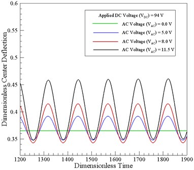
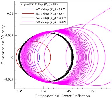
Fig. 5 shows the phase portraits of the circular micro-plate for a constant DC voltage of 94 V and AC voltages of 5.0 V, 8.0 V,11.5 V and 12.0 V, respectively. The results show that for an AC voltage less than 12.0 V, the system exhibits a stable behavior, i.e., the size of the orbit remains approximately constant over time. However, for an actuating voltage of 12.0 V, the size of the orbit gradually increases until the system becomes unstable and the pull-in event occurs.
Table 3Material and geometry parameters of the circular micro-plate
Parameters / Symbol / Unit | Value |
Young’s modulus () (GPa) | 130 |
Poisson’s Ratio () | 0.23 |
Density () (kg/m3) | 2330 |
Thickness of circular plate () (μm) | 1.0 |
Initial gap () (μm) | 1.0 |
Radius () (μm) | 45 |
Fig. 5Phase portraits for the circular micro-plate given constant DC voltage of 94 V
5. Conclusions
The present study has analyzed the nonlinear dynamic behavior of the microelectromechanical electrostatic actuators subject to a squeeze-film damping effect by using a hybrid numerical scheme comprising the differential transformation method and the finite difference method. The validity of the proposed scheme has been confirmed by comparing the predicted value of the pull-in voltage for the micro-beam with the results presented in the literature. Finally, it has been shown that the stability of the circular micro-plate reduces as the magnitude of the AC voltage increases. Overall, the numerical results presented in this study show that the hybrid numerical scheme provides an accurate and computationally-efficient means of analyzing the nonlinear dynamic behavior of the microelectromechanical electrostatic actuators used in many of today’s MEMS-based systems.
References
-
Zhu Y., Espinosa H. D. Effect of temperature on capacitive RF MEMS switch performance – a coupled-field analysis. Journal of Micromechanics and Microengineering, Vol. 14, 2004, p. 1270-1279.
-
http://www.freescale.com/.
-
Bosc J. M., Guo Y., Sarihan V., Lee T. Accelerated life testing for micro-machined chemical sensors. IEEE Transactions on Reliability, Vol. 47, Issue 2, 1998, p. 135-141.
-
Maluf N. I., Reay R. J., Kovacs G. T. A. High-voltage devices and circuits fabricated using foundry CMOS for use with electrostatic MEM actuators. Sensors and Actuators A, Vol. 52, 1996, p. 187-192.
-
Luharuka R., LeBlanc S., Bintoro J. S., Berthelot Y. H., Hesketh P. J. Simulated and experimental dynamic response characterization of an electromagnetic microvalve. Sensors and Actuators A, Vol. 143, 2008, p. 399-408.
-
Rezazadeh G., Tahmasebi A., Zubstov M. Application of piezoelectric layers in electrostatic MEM actuators: controlling of pull-in voltage. Microsystem Technologies, Vol. 12, 2006, p. 1163-1170.
-
Varadan V. M., Vinoy K. J., Jose K. A. RF MEMS and Their Applications. Wiley, New York, 2003.
-
Liu C. C., Chen C. K. Modeling and simulation of nonlinear micro-electromechanical circular plate. Smart Science, Vol. 1, Issue 1, 2013, p. 59-63.
-
Chao P. C., Chiu C. W., Tsai C. Y. A novel method to predict the pull-in voltage in a closed form for micro-plates actuated by a distributed electrostatic force. Journal of Micromechanics and Microengineering, Vol. 16, 2006, p. 986-998.
-
Chen C. K., Lai H. Y., Liu C. C. Application of hybrid differential transformation/finite difference method to nonlinear analysis of micro fixed-fixed beam. Microsystem Technologies, Vol. 15, 2009, p. 813-820.
-
Younis M. I., Abdel-Rahman E. M., Nayfeh A. A reduced-order model for electrically actuated microbeam-based MEMS. Journal of Microelectromechanical Systems, Vol. 12, 2003, p. 672-680.
-
Vogl G. W. V., Nayfeh A. A reduced-order model for electrically actuated clamped circular plates. Journal of Micromechanics and Microengineering, Vol. 15, 2005, p. 684-690.
-
Liu C. C., Wang C. C. Numerical investigation into nonlinear dynamic behavior of electrically-actuated clamped-clamped micro-beam with squeeze-film damping effect. Applied Mathematical Modelling, Vol. 38, 2014, p. 3269-3280.
-
Krylov S., Maimon R. Pull-in dynamics of an elastic beam actuated by continuously distributed electrostatic force. ASME Journal of Vibration and Acoustics, Vol. 126, Issue 3, 2004, p. 332-342.
-
Younis M. I. Investigation of the Mechanical Behavior of Microbeam-Based MEMS Devices. Master of Science Thesis, Virginia Polytechnic Institute and State University, 2001.
-
Zhou X. Differential Transformation and its Applications for Electrical Circuits. Huazhong University Press, Wuhan, China, 1986, (in Chinese).
-
Liu C. C., Liu C. H. Analysis of nonlinear dynamic behavior of electrically-actuated micro-beam with piezoelectric layers and squeeze-film damping effect. Nonlinear Dynamics, Vol. 77, Issue 4, 2014, p. 1349-1361.
-
Lamoreaux S. K. The Casimir force: background, experiments, and applications. Reports on Progress in Physics, Vol. 68, Issue 1, 2005, p. 201-236.
About this article

The authors gratefully acknowledge the financial support provided to this study by the Ministry of Science and Technology of Taiwan under Grant Number MOST 104-2221-E-018-022.
