Abstract
The force between wheels and rails of the high-speed train was firstly extracted and applied into the computational model of radiation noises of wheels and rail respectively. As a result, the radiation noise of wheels and rails was obtained. As can be seen from the result, radiation noises of wheels had an obvious directivity on the body surface, while radiation noises of rails had an obvious periodicity on the body surface. With the increase of the analyzed frequency, both directivity and periodicity were shown more obviously. Then the aerodynamic model of the high-speed train was established, and the pressure and velocity distributions on the train surface were computed. The maximum pressure was at the tip of the nose of the high-speed train, the maximum velocity was at the transition of the cabin, and more serious eddy was in the rear of the high speed train. Based on the computed pressure distribution, the aerodynamic noise was distributed evenly on the entire body surface, which was gradually increased with the increasing analyzed frequency. Finally, the wheel radiation noise, rail radiation noise and aerodynamic noise were extracted as excitations and applied into the SEA (Statistical Energy Analysis) model of the high-speed train, in order to compute its full-spectrum noise under multi-physics coupling excitations. The computational result was compared with the experimental result. It was presented that the difference of average sound pressure level (SPL) was 2.8 dB between the experimental and numerical simulations within the entire analytical frequency band. The SEA model with considering the multi-physics coupling was effective.
1. Introduction
As the development direction of the modern rail transportation, the speed of the high-speed train has been constantly improved in the world. However, the aggravation of noise pollution will be caused inevitably by the further speed of the train. Therefore, the effective measure that can control interior noise of the high-speed train to the tolerable range of its passengers has become a very important issue.
Regarding acoustic problems, a lot of achievements have been obtained for noise researches of the high-speed train [1-5]. Xiao [6] established the rail dynamics model, BIW finite element model and boundary element model of the train head, and computed the distribution of indoor noises caused by the rail irregularity. However, the acoustic performances of wheel-rail noises, aerodynamic noises, and other major excitation sources as well as interior trims were neglected. Liu [7] computed the externally unsteady flow field of the high-speed train, extracted the surface fluctuation pressure, and analyzed aerodynamic noises of the wheel based on SEA theories. However, the interior noise under other excitations was ignored. The train was impossible to stay only in the excitation of the external flow field. When it was under multiple coupling excitations, its interior acoustic characteristic would be changed completely. By using hybrid method, Sapena [8] established a plate-beam model of the cabin and computed the indoor noise, where the interior trims were equalized as a sound absorption coefficient, the coupling effect of mechanical excitation and aerodynamic noise excitation was considered. However, the wheel-rail noise was ignored. The wheel-rail coupling dynamic model of the high-speed train, BIW finite element model and acoustic boundary element model of the passenger cabin were established in reference [9, 10] to analyze the distribution of indoor noises caused by the track irregularity. And the acoustic transfer vector technology was applied to analyze the contribution of the passenger cabin panel to the maximum acoustic pressure point. These researches only predicted the passenger cabin noise generated by the forced vibration of the structure of the high-speed train. However, the quantitative computation and analysis regarding the contribution of train body parts with sound absorption materials and damping materials to the passenger cabin noise were not mentioned. Jang [11] analyzed characteristics of wheel-rail vibrations to study the rolling noise, but the analyzed frequency was only within 4000 Hz and the researched results were not verified by experiments.
The coupling excitations between wheel noises, rail noises and aerodynamic noises were not considered comprehensively in the mentioned researches. Only a single factor or the superimposition of two factors was studied, and the computational result could not reflect the actual situation. Additionally, the researched approaches were based on finite element method and boundary element method, and the computational result only reflected the noise situation in the mid-low frequency band. Wheel noises, rail noises, aerodynamic noises and other coupling excitations were considered comprehensively, and SEA method was applied to compute the full-spectrum noise of the high-speed train in the paper. The researched result was more consistent with the actual situation, and more comprehensive factors were considered, which provided a more reliable method for the low noise design of the high-speed train.
2. Basic theories
The successful application of SEA in vibro-acoustic transfer has offered a new method to predict vibro-acoustic response of building structures, aviation, ships and transport vehicles. Energy was the basic variable. SEA method mainly studied the transfer and distribution of the average vibration energy under steady vibrations. Normally, the system is divided into several subsystems according to some principles. When the vibration was steady, the additional excitation input energy through its subsystem. Each subsystem stored energy during vibrations, and energy was dissipated using damping. Energy was transferred by the subsystem [12]. According to Conservation Law of Energy, a system comprised of subsystems has the following energy balance equation:
wherein, 1, 2,...,, . was the input power from external excitation source to the th subsystem. was the damping loss power of the th subsystem. was the total energy of the th subsystem stored in the analyzed band. was the central angular frequency of its band. was the loss factor of the th subsystem. was the power transferred from the th subsystem to the th subsystem during the vibration process. was the coupling loss factor from subsystem to . was the modal density of the th subsystem. According to the reciprocity principle, the following equation could be obtained:
Eqs. (2), (3) and (4) were substituted into Eq. (1) and written in the matrix form, which could obtain the following formula:
wherein, . Coefficients [13] in Eq. (5) were determined, and then such equation was solved band by band. Therefore, the average response energy of each subsystem in the band could be obtained, which could be converted to the response of sound pressure levels.
3. Models of multi-physics excitation
3.1. Wheel-rail forces
Wheel-rail forces could be obtained by rigid multi-body dynamics. The dynamics model and main parameters of the train were shown as Fig. 1 and Table 1, respectively.
The train body was equalized as a rigid mass block in modelling, including gravity position, mass, inertia and so on. Bogies were equalized as a wheel-set, frame, anti-snake damper, horizontal hydraulic buffer, first suspension, and secondary suspension, etc. As presented in Fig. 2, the track spectrum of the high-speed train was obtained by multiple experiments and used as the excitation source to input to the multi-body dynamics model. It was shown from Fig. 2 that the track spectrum of four wheel-sets of the high-speed train was not exactly same, but they fluctuated near a constant magnitude. The fluctuations of the vertical track irregularity of the high-speed train was significantly more serious than that of the transverse track irregularity, which was primarily caused by the radial modal from wheel-sets of the high-speed train. The relatively serious vibration under the excitation force was motivated. Based on track spectrum and multi-body dynamics model, the wheel-rail force of the high-speed train could be obtained and further applied to the finite element model to obtain the corresponding structural response.
Fig. 1Rigid multi-body dynamics
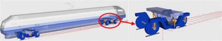
Table 1Main parameters of rigid multi-body dynamics model
Body mass / t | Roll inertia / (t.m2) | Nod inertia / (t.m2) | Shaking inertia / (t.m2) | Height of gravity / m |
33.3 | 110 | 1636 | 1569 | 1.65 |
Longitudinal stiffness of steel spring / (kN.m-1) | Lateral stiffness of steel spring / (kN.m-1) | Vertical stiffness of steel spring / (kN.m-1) | Horizontal stiffness of air spring / (kN.m-1) | Vertical stiffness of air spring / (kN.m-1) |
920 | 920 | 886±60 | 125 | 195 |
3.2. Radiation noises of wheels
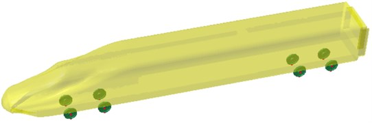
The wheel-rail force obtained by the multi-body dynamics model was applied to the finite element model of wheels to compute their structural response. Then, the finite element model of wheels was imported into Virtual.Lab to couple with the boundary element model. Therefore, the boundary element model could obtain the result of the finite element model. As a result, the vibro-acoustic coupling can be realized. The field point meshes were established to compute the radiation noise of wheels on the high-speed train surface, whose final model was shown in Fig. 3.
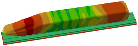
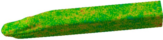
Through the computational model of radiation noises of wheels, the sound pressure contour on the high-speed train surface could be obtained, as shown in Fig. 4. It was found from Fig. 4 that at 100 Hz, wheels had the relatively large radiation noise in their corresponding positions on the high-speed train surface, and the radiation noise of front wheels was significantly greater than that of rear wheels. At 1000 Hz, the directivity of radiation noises of wheels became more obvious. When the analyzed frequency was 1600 Hz, the radiation noise near wheels was relatively large, while the radiation noise of rear wheels had turned very weak.
Fig. 2Track spectrum of the high-speed train
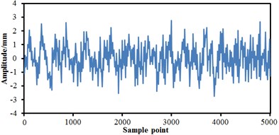
a) Transverse track irregularity on the left side
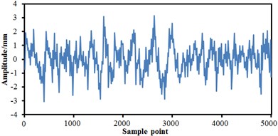
b) Vertical track irregularity on the left side
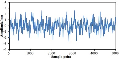
c) Transverse track irregularity on the right side
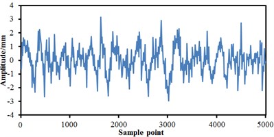
d) Vertical track irregularity on the right side
Fig. 3Computational model of radiation noises of wheels
3.3. Radiation noises of rails
According to the actual rail structure, the finite element model of slab track was established, including steel rail, fastener, track panels, base and foundation beam. FEM parameters of the track were presented in Table 2. The wheel-rail force obtained through the multi-body dynamics model was applied to the rail, and the structural response of the rail was obtained, which was imported into Virtual.Lab to couple with the boundary element model. The high-speed train surface was treated as the field point, in order to establish the radiation noise model of rails, as shown in Fig. 5.
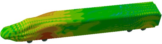
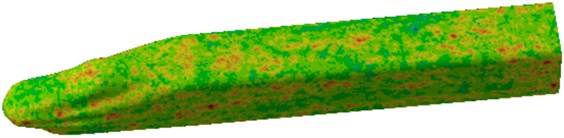
Through the computational model of radiation noises of rails, the sound pressure contour of radiation noises of rails could be obtained, as shown in Fig. 6. At 100 Hz, maximum radiation noises of rails could be found in front and rear wheels because excitation sources were applied there, therefore the vibration amplitude was relatively large. At 500 Hz, the obvious periodicity of radiation noises of rails was found on the high-speed train surface, and the radiation noise of the cabin was relatively great. At 1000 Hz, the periodicity of radiation noises was more evident, and the radiation noise of the cabin was significantly larger than that of other positions. At 1600 Hz, the periodicity of radiation noises was further intensified since the track could be equalized as a beam structure, whose modes presented clear periodicity and thereby reflected in the radiation noise.
Fig. 4Sound pressure contours of radiation noises of wheels

a) 100 Hz

b) 500 Hz
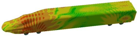
c) 1000 Hz
d) 1600 Hz
Table 2FEM parameters of the track
Structure | Density / (kg.m-3) | Elastic modulus / GPa | Poisson’s ratio |
Steel rail | 7850 | 210 | 0.3 |
Track panels | 2500 | 36 | – |
Base | 2500 | 40 | 0.2 |
Structure | Vertical stiffness / (N.m-1) | Vertical damping / (N.s.m-1) | Distance / m |
Fastener | 6.0×10⁷ | 3.625×10⁴ | 0.6 |
Foundation beam | 1.2×10⁸ | 1.000×10⁵ | – |
Fig. 5Computational model of radiation noises of rails
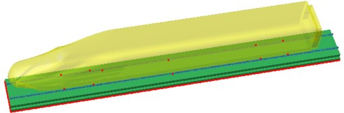
Fig. 6Sound pressure contours of radiation noises of rails
a) 100 Hz
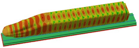
b) 500 Hz
c) 1000 Hz
d) 1600 Hz
3.4. Aerodynamic noises
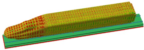
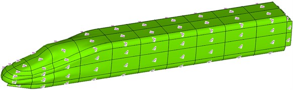
The aerodynamic computation model of the high-speed train was built, as shown in Fig. 7. Velocity was chosen as the inlet boundary condition, pressure was the outlet boundary condition, the bottom of the high-speed train was set as a fixed wall, and the lateral sides and the top were set as the sliding boundary condition. This computational model had 545272 elements and 612097 nodes. The model had selected the steel as materials, elastic modulus was 2.1e11, density was 7800 kg/m3, and Poisson’s ratio was 0.31. Based on the computational model, the pressure and velocity distribution of the high-speed train could be obtained under the aerodynamic. As presented from the pressure distribution on the high-speed train surface in Fig. 8(a), the maximum pressure could be observed at the tip of the nose of the high-speed train, which was primarily because the nose tip was the initial position of the aerodynamic effect, and there was a relatively large pressure difference. With the time, the air gradually moved toward the rear of the high-speed train. Besides, the pantograph, bogie, and other accessories were ignored in the model. The top and bottom of the high-speed train was equalized as a planar structure; therefore, the pressure distribution was more even. However, in the rear position of the high-speed train, the pressure was fluctuated mainly because some blank region was in the rear and it would easily form vortexes, which was reflected in the velocity distribution in Fig. 8(b).
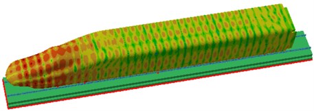
The computed aerodynamic characteristics of the high-speed train were treated as the result and imported into Virtual.Lab, in order to compute the aerodynamic noise of the high-speed train, as shown in Fig. 9. The distribution of aerodynamic noises was obviously different from that of wheel noises and rail noises, which were primarily because the excitation source of wheel noises and rail noises was a concentrated force, while that of the aerodynamic noise was air that uniformly distributed on the entire train. With the increase of the analyzed frequency, the aerodynamic noise on high-speed train surface was significantly increased because aerodynamic noises were mainly reflected in the high frequency, and mechanical noises played a major role in the low frequency.
Fig. 7Wind tunnel models of the high-speed train
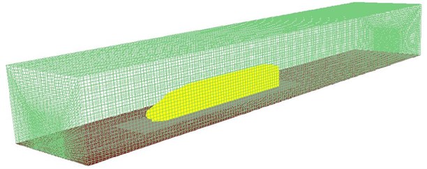
Fig. 8Pressure and velocity distributions of the high-speed train
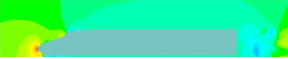
a) Pressure distribution
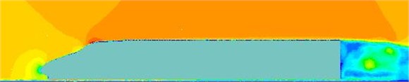
b) Velocity distribution
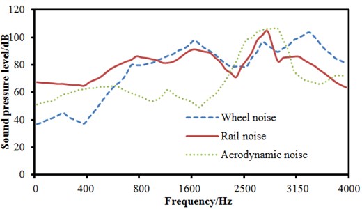
The observation points at the same position were selected from the computational models of wheel noises, rail noises and aerodynamic noises. And 1/3 octave results of wheel noises, rail noises and aerodynamic noises were obtained at 350 km/h, as shown in Fig. 10. It could be seen from the figure that the maximum peaks were at 1200 Hz, 1800 Hz and 3000 Hz, respectively, which was basically consistent with the experimental conclusions obtained by Mellet [14].
4. Computation and analysis of full-spectrum noises of the high speed train
4.1. SEA model of the high-speed train
A close relationship was presented between the finite element model and SEA model of the high-speed train. When the finite element model was established, the high-speed train was divided into two systems, namely BIW and interior trims [15-17]. BIW finite element model was composed of two-dimensional quadrilateral elements that were featured with cross-sectional characteristics of aluminum profile. From the bottom to the top, interior trims were made up of thermal insulating layer, sound absorption layer, flooring system, seats, windows and doors, wooden partition and luggage racks. Each structure in interior trims was separately divided into the finite element model and then connected through constraints. Finally, the finite element model of interior trims was obtained. The finite element models of BIW and interior trims were assembled together through constraints, in order to obtain a finite element model of the high-speed train. Based on the FEM, SEA model was consisted of four parts, namely exterior sound cavity subsystem, BIW structural subsystem, interior sound cavity subsystem and surface and line connections of subsystems. The exterior sound cavity subsystem was applied to load and couple acoustic excitations of different physical fields, which was the input portion of acoustic energy flow, as shown in Fig. 11. Acoustic performances of panels were directly defined as the connection surface of BIW structural subsystem and interior sound cavity subsystem, as shown in Fig. 12.
Fig. 9Sound pressure contours of aerodynamic noise
a) 100 Hz
b) 500 Hz
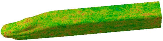
c) 1000 Hz
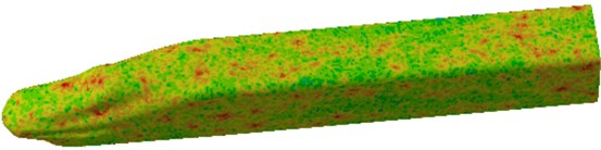
d) 1600 Hz
Fig. 10Simulation models and results of exterior noises
The previously wheel radiation noise, rail radiation noises, aerodynamic noises and other excitations were imported into VAONE, and then applied to SEA model of the high-speed train, in order to obtain a computational mode of full-spectrum noises as shown in Fig. 13. Multi-physics coupling excitation [18-20] was considered in the model, which was more consistent with the actual condition.
Fig. 11Sound cavity subsystems of the high-speed train
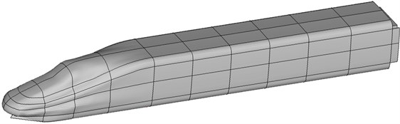
Fig. 12Face and line connections of subsystems of the high-speed train
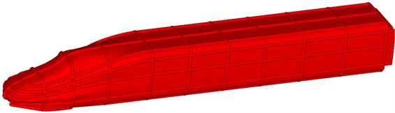
Fig. 13SEA model of the high-speed train
4.2. Parameters of SEA model of the high-speed train
Before computing the interior noise, the parameters of SEA model were also required based on experiments, namely internal loss factor of interior sound cavity, sound absorption coefficient of seat material, and transmission loss of the perforated plate in the train. Internal loss factor of interior sound cavity can be obtained by equations, whose result was shown as Fig. 14.
Fig. 14Internal loss factor of the interior sound cavity
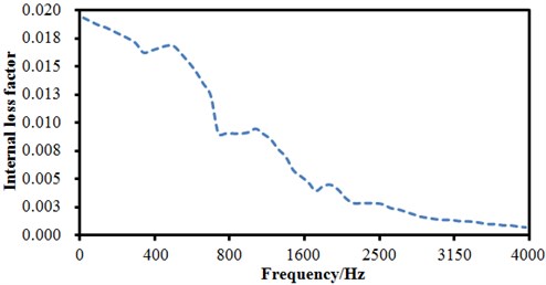
Generally, it was decreased gradually with the increase of the analyzed frequency, and stabilized in a smaller magnitude in the high frequency. The sound absorption coefficient of seat materials was measured through the standing wave tube method with four sensors [21, 22], whose measurement process was shown as Fig. 15(a) and measurement result was shown in Fig. 15(b). The sound absorption coefficient of seat materials was increased with the analyzed frequency. And the transmission loss of the perforated plate was measured within the laboratory made by a reverberation chamber and an anechoic chamber, as shown in Fig. 16(a). The perforated plate was fixed on the window between reverberation chamber and anechoic chamber, and the gap between the perforated plate and window was sealed by sludge to prevent sound leakage and affecting the experimental results. The finally transmission loss was obtained and shown in Fig. 16(b).
Fig. 15Experimental sound absorption coefficient of seat materials
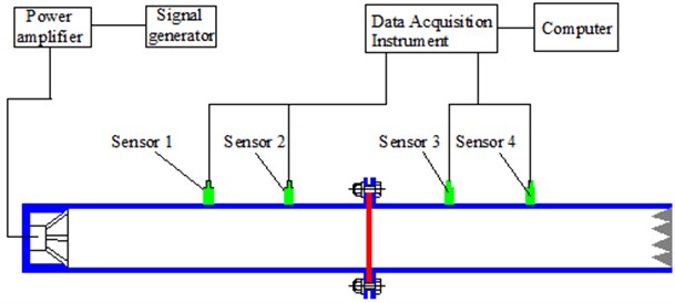
a) Standing wave tube method with four sensors
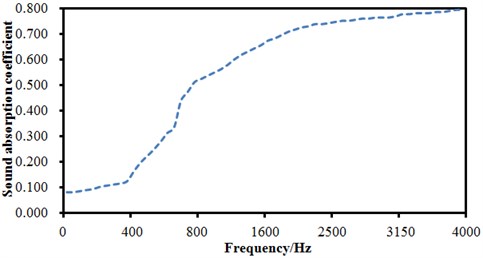
b) Sound absorption coefficient of seat materials
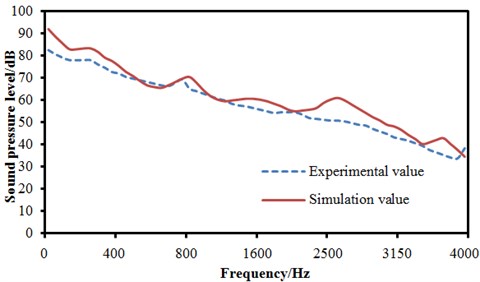
After computation, the acoustic response of the interior sound cavity subsystem was obtained under the multi-physics coupling excitation. The sound cavity at 1.2 m away from the floor in the center vehicle was selected for the detailed research, and the sound pressure level within 0 Hz-4000 Hz was obtained. At the speed of 350 km/h, the sound pressure levels of same positions were tested to verify the reliability of numerical results. The interior sound pressure computed by SEA method was compared with the experimental result as shown in Fig. 17. As can be seen from the figure, the change trend of the computational value of the interior sound cavity was basically consistent with that of the experimental value within 0 Hz-4000 Hz. When the analyzed frequency was lower than 300 Hz, the simulation and experimental values had a great error because performances of train panels were seriously affected by the boundary conditions in the low frequency. In the central frequency of 2500 Hz, the simulation and experimental errors were primarily caused because the inadequate accuracy of the rail model had resulted in the relative large rail noises, thereby leading to the larger interior noise. At other frequencies, the simulation and experimental errors were generally controlled within 3 dB to satisfy the engineering requirements. In addition, the average simulation and experiment sound pressure values in the whole band were 69.7 dB and 66.9 dB respectively, with a difference of 2.8 dB.
Fig. 16Experimental process and result of transmission loss of the perforated plate
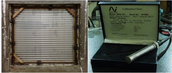
a) Experimental process of transmission loss of the perforated plate
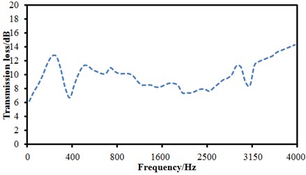
b) Experimental result of transmission loss of the perforated plate
Fig. 17Experiment and comparison of interior sound pressure
5. Conclusions
1) The force between wheels and rails of the high-speed train was firstly extracted and applied into the computational model of radiation noises of wheels and rail respectively. As a result, the radiation noise of wheels and rails was obtained. As can be seen from the result, radiation noises of wheels had an obvious directivity on the body surface, while radiation noises of rails had an obvious periodicity on the body surface. With the increase of the analyzed frequency, both directivity and periodicity were shown more obviously.
2) The aerodynamic model of the high-speed train was established, and the pressure and velocity distributions on the train surface were computed. The maximum pressure was at the tip of the nose of the high-speed train, the maximum velocity was at the transition of the cabin, and more serious eddy was in the rear of the high speed train. Based on the computed pressure distribution, the aerodynamic noise was distributed evenly on the entire body surface, which was gradually increased with the increase of the analyzed frequency.
3) The wheel radiation noise, rail radiation noise and aerodynamic noise were extracted as excitations and applied into the SEA (Statistical Energy Analysis) model of the high-speed train, in order to compute its full-spectrum noise under multi-physics coupling excitations. The computational result was compared with the experimental result. It was presented that the difference of average sound pressure level (SPL) was 2.8 dB between the experimental and numerical simulations within the entire analytical frequency band. The SEA model with considering the multi-physics coupling was effective.
References
-
Kurita T. Development of external-noise reduction technologies for Shinkansen high-speed trains. Journal of Environment and Engineering, Vol. 6, Issue 4, 2011, p. 805-819.
-
Jeon J. Y., Jang H. S., Hong J. Y. Evaluation of speech privacy in passenger cars of high-speed trains based on room acoustic parameters. Acta Acustica United with Acustica, Vol. 100, Issue 4, 2014, p. 649-658.
-
Noh H. M., Choi S., Kim S. W., et al. A study on interior noise characteristics of high-speed trains. Journal of the Korean society for railway, Vol. 16, Issue 1, 2013, p. 14-19.
-
Kurita T., Hara M., Yamada H., et al. Reduction of pantograph noise of high-speed trains. Journal of Mechanical systems for Transportation and Logistics, Vol. 3, Issue 1, 2010, p. 63-74.
-
Kurita T., Wakabayashi Y., Yamada H., et al. Reduction of wayside noise from Shinkansen high-speed trains. Journal of Mechanical Systems for Transportation and Logistics, Vol. 4, Issue 1, 2011, p. 1-12.
-
Xiao Y. G., Kang Z. C. Acoustic contribution analysis of passenger room of high-speed train under wheel-rail excitation. Journal of South China University of Technology: Natural Science Edition, Vol. 37, Issue 2, 2009, p. 98-106.
-
Liu J. L., Zhang J. Y., Zhang W. H. Calculation method of interior aerodynamic noises with middle and high frequencies for high-speed train. Journal of Traffic and Transportation Engineering, Vol. 11, Issue 3, 2011, p. 55-60.
-
Sapena J., Tabbal A., Jove J. Interior noise prediction in high-speed rolling stock driver’s cab: Focus on structure-borne paths (mechanical and aero-sources). Noise and Vibration Mitigation for Rail Transportation Systems, Vol. 118, 2012, p. 445-452.
-
Shi Y., Xiao Y. G., Kang Z. C. Interior noise investigation for a passenger room of a high speed train under wheel-rail excitation. Journal of Vibration and Shock, Vol. 28, Issue 1, 2009, p. 95-98.
-
Xiao Y. G., Kang Z. C. Acoustic contribution analysis of passenger room of high-speed train under wheel-rail excitation. Journal of South China University of Technology, Vol. 37, Issue 2, 2009, p. 98-101.
-
Jang S., Ryue J. Study on the rolling noise model using an analysis of wheel and rail vibration characteristics. Journal of the Korean Society for Railway, Vol. 16, Issue 3, 2013, p. 175-182.
-
Lyon R. H. Theory and Application of Statistical Energy Analysis. Elsevier, 2014.
-
Xiang S. H., Wang D. J., Yu D. Comprehensive method of SEA parameter determination and its applications. Journal of Vibration Engineering, Vol. 17, Issue 4, 2004, p. 477-482.
-
Mellet C., Letourneaux F., Poisson F. High speed train noise emission: Latest investigation of the aerodynamic/rolling noise contribution. Journal of Sound and Vibration, Vol. 293, Issues 3-5, 2006, p. 525-546.
-
Li J. Q., He S. Q., Ming Z. An intelligent wireless sensor networks system with multiple servers communication. International Journal of Distributed Sensor Networks, Vol. 7, 2015, p. 1-9.
-
Li J. Y., Qiu M. K., Ming Z. Online optimization for scheduling preemptable tasks on IaaS cloud systems. Journal of Parallel and Distributed Computing, Vol. 72, Issue 5, 2012, p. 666-677.
-
Zhu Z. X., Xiao J., Li J. Q. Global path planning of wheeled robots using multi-objective memetic algorithms. Integrated Computer-Aided Engineering, Vol. 22, 2015, p. 387-404.
-
Li J. Q., Li J., Fu X. H. Learning distributed word representation with multi-contextual mixed embedding. Knowledge-based Systems. Vol. 106, 2016, p. 220-230.
-
Wei W., Fan X., Song H., et al. Imperfect information dynamic Stackelberg game based resource allocation using hidden Markov for cloud computing. IEEE Transactions on Services Computing, 2016.
-
Lin Q. Z., Zhu Q. L., Huang P. Z., Chen J. Y., Ming Z., Yu J. P. A novel hybrid multi-objective immune algorithm with adaptive differential evolution. Computers and Operations Research, Vol. 65, 2015, p. 95-111.
-
Chen J. Y., Lin Q. Z., Hu Q. B. Application of novel clonal algorithm in multiobjective optimization. International Journal of Information Technology and Decision Making, Vol. 9, Issue 2, 2010, p. 239-266.
-
Wei W., Xu Q., Wang L., et al. GI/Geom/1 queue based on communication model for mesh networks. International Journal of Communication Systems, Vol. 27, Issue 11, 2014, p. 3013-3029.
About this article

