Abstract
Aiming at the nozzle-diverted channel system, two diverted channels with different configurations were designed and optimized, and the liquid flow characteristics in the diverted channel were studied. A finite element simulation model was established to analyze the influence of different diverted channel systems on the uniform distribution performance of the liquid, and the two diverted channels were tested for the uniform distribution of liquid flow. The results show that the diverting effect of the two kinds of diverting disk channels is relatively uniform. However, the distribution performance of the four-bifurcated diverting disk channel is better than that of the double-bifurcated diverting disk channel. The pressure loss is relatively less; the energy consumption is less, so the four-bifurcated diverting disk channel system is selected as the optimal design. The experimental results are consistent with the simulation results.
Highlights
- A component diverter plate for diverting liquid in a nozzle is proposed.
- The liquid flow characteristics in the diverted channel were studied.
- Through simulation, it is found that the distribution performance of the four-bifurcated diverter channel is better than that of the two-bifurcated diverter channel, and the accuracy of the simulation is verified by experiments.
- In the design of the runner system, the distribution performance of liquid can be improved by increasing the number of runner forks as much as possible under certain conditions.
- The efficiency of the spray head can be improved by improving the distribution performance of liquid in the runner.
1. Introduction
Uniform flow distribution is a widespread and essential problem in many engineering environments. In modern agricultural irrigation systems, uniform flow distribution means irrigating more farmland with less water. Biologists have shown that uniform flow distribution helps to reduce the flow resistance in the vascular system [1]. Examples of industrial processes and equipment requiring uniform flow distribution abound, such as radiators [2], trickle bed reactors [3], electrostatic precipitators (ESP) [4], multi-channel plate-fin heat exchangers [5] and packed columns, which perform better when they exhibit uniform flow distribution during operation. If the flow distribution is uneven, it will cause harmful effects. For example, Kim [6] and others found that when the flow in multiple channels is uneven, it will lead to the heat transfer difference between channels, thus reducing the system's effectiveness and affecting the equipment's use efficiency. Uniform flow distribution is advantageous in providing better heat transfer, temperature control, and pressure loss.
In this paper, two kinds of diverter channels with different configurations are studied, and the uniform distribution performance of the liquid flow is compared using simulation and experiment, which guides the design of the new spray head.
2. Modeling and simulation of diverter channel
2.1. Model of geometry
Fig. 1 shows the distributary channel model optimized according to the principle of symmetry and the construction method [7], where a is a double-bifurcated (two-sub-channel) distributary channel, and b is a four-bifurcated (four-sub-channel) distributary channel, which is smoothest at the flow steering and inlet.
Fig. 1The geometric model of the diverter channel
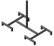
a) Double bifurcation channel
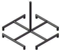
b) Four bifurcation channel
According to structural theory, the length is determined by the following formula:
where is the series of fractal tree networks, is the length of the channel at each level, is the number of bifurcated trees, and is the fractal dimension of length, where = 2. In the double-bifurcated flow channel, = 25 mm is designed here, and = 17.7mm and = 12.5mm are obtained by calculation. In the four-bifurcated flow channel, = 2 is also taken as the second grade is two-bifurcated, = 32.3 mm is designed here, and = 22.9mm is calculated.
2.2. Mathematical solution model
Since the calculation of fluid flow in the three-dimensional model at constant temperature is carried out in this paper, energy conservation is not considered. In the simulation, laminar flow model is used Therefore, the governing equation of flow is as follows.
Mass conservation equation:
Momentum conservation equation:
where is the density, , and are the components of the velocity vector in the , , and directions, and is the pressure on the fluid element.
For the fluid flow in a circular pipe, only the internal shear force is considered, and the value of the fluid shear force on the inner micro-control body satisfies the following formula:
If you change the length into , you can get:
where is the pressure difference between the inlet and outlet of the micro-control body; Micro control body radius.
The sheer force inside the tube flow changes linearly along the radial direction and is maximum at the wall surface and zero at the centre. Therefore, the velocity is complete at the centre.
The computational fluid dynamics software Fluent is used to simulate the three-dimensional flow in the two models in Fig. 1. Water is used as a liquid working medium, and the inlet flow rate is controlled at 1000-5000 μL/min. The boundary conditions and other settings are shown in Table 1.
Table 1Boundary conditions and other Settings of the shunt plate during simulation
Parameter category | Settings |
Entrance boundary condition | Volume flow inlet |
Exit boundary condition | Pressure outlet, set the pressure value to zero |
Flow boundary conditions on the wall | All walls have no slip boundary |
Axisymmetric boundary condition | The centre of the pipeline is set to be axisymmetric |
Pressure-velocity coupling | SIMPLEC |
Discrete scheme of pressure equation | Adopt standard format |
Discretization of mass equation and momentum equation | QUICK format is adopted |
3. Simulation results and analysis
In order to study the liquid flow trend in the diverter channel, the simulation results were post-processed. In this work, two dimensionless parameters are used to evaluate the uniformity of flow distribution, namely, standard flow deviation and maximum flow ratio , which are defined as:
where is the number of exits, is the flow velocity of the th exit, is the average flow velocity of each exit, and is the maximum flow velocity at the exit. is the minimum flow velocity at the exit. When the fluid distribution reaches an ideal uniform state, the closer is to 0, and is to 1; otherwise, if deviates from 0 and deviates from 1, the fluid distribution is uneven.
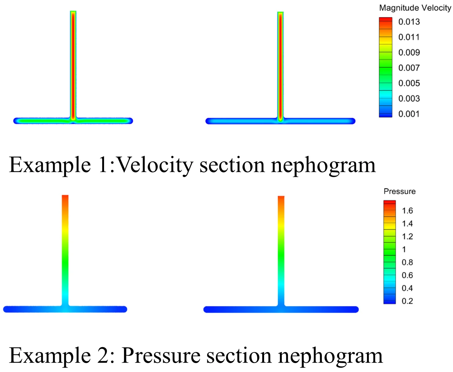
Fig. 2 and Fig. 3 shows the model’s velocity cross-section program and pressure cross-section program along the plane. The model's velocity and pressure cross-section program are roughly symmetrical, indicating that the shunt effect of the model is relatively uniform.
Fig. 2Velocity section nephogram
a) Double bifurcation channel
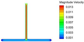
b) Four bifurcation channel
Fig. 3Pressure section nephogram

a) Double bifurcation channel
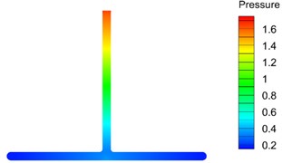
b) Four bifurcation channel
In order to better demonstrate this effect numerically, two particular paths were created along the horizontal direction of the -axis. The change trend curve of velocity and pressure along the path direction was obtained through analysis, as shown in Fig. 4. It is evident from Fig. 4 that both the velocity curve and the pressure curve are roughly symmetric concerning the line 0, which further indicates that the shunt effect of the model is relatively uniform.
Fig. 4Variation curves of velocity and pressure values along the X-axis of different models, where 2 represents the two-fork flow channel model, and 4 illustrates the four-fork flow channel model
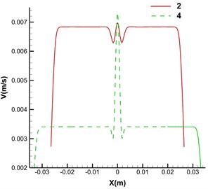
a) Velocity curve
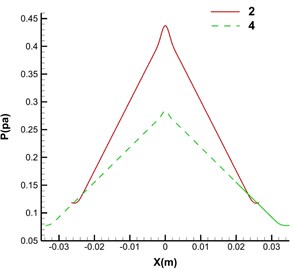
b) Pressure curve
Fig. 5 shows the relationship between the flow distribution uniformity of the optimized shunt channel and the average at the outlet. It can be seen that both and four-fork channels are more minor than double-fork channels, indicating that the liquid distribution performance of the four-fork channel is better than that of the double-fork channel because the four-fork channel has two more groups of channels than the double-fork channel. Based on structural theory, it is shown that increasing the number of channel groups can effectively improve the distribution performance of liquid.
Fig. 5Flow distribution performance of different models
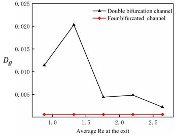
a) Relation between and exit mean
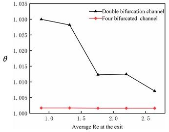
b) Relation between and exit mean
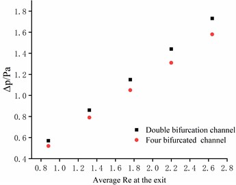
Fig. 6 shows the relationship between the pressure drop of the two kinds of shunt plate channels and the average at the outlet. It can be seen that the pressure drop of the four-fork channel is lower than that of the two-fork channel. Appropriately increasing the number of channel groups can reduce the pressure drop of the liquid in the distribution process, namely reducing energy dissipation.
Fig. 6The relation between ΔP and outlet average Re of different model flow channels
In the Hagan-Poiseuille flow, the resistance of the flow passage is:
Then the resistance in the double bifurcation channel is:
The resistance in the four-fork channel is:
where is pressure loss, is volume flow, is dynamic viscosity, is the length of flow passage, and is the diameter of the flow passage.Obviously, >, indicating that the pressure drop of the two-fork channel is more significant than that of the four-fork channel, that is, more energy is consumed, which theoretically verifies the accuracy of the simulation.
4. Experiment of uniform flow of liquid
4.1. Experimental device
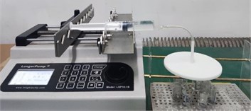
In order to verify the above simulation results, two sets of comparison tests were designed. The experimental platform comprises a liquid supply system, shunt plate system, liquid collection system and measurement system. The practical device is shown in Fig. 7 (the photo is taken at Advanced Manufacturing Research Laboratory, Changchun University of Science and Technology; courtesy of Jianhe Liu).
The injection pump is a liquid supply device. In the experiment, the capacity of the injection pump is set as 20 mL, and all 20 mL liquid is distributed to each small beaker through the shunt plate within a certain period. Water is used as the working fluid, and the mass of the collected liquid is measured by using an electronic balance with a weighing accuracy of 0.1 mg.
The velocity at the outlet of the shunt plate was used to measure the uniform distribution performance of the liquid above. Here, the mass of the liquid collected at the outlet of each shunt plate can be similarly used to evaluate the uniform distribution performance of the liquid, i.e., standard mass deviation , maximum mass ratio . There may be specific errors and contingencies in a single experiment. In order to eliminate the influence brought by this, the experiment was repeated 5 times.
Fig. 7Diagram of experimental equipment for uniform flow of liquid
4.2. Experimental results
Fig. 8 shows the relationship between the number of experiments and and . It is found that and of the four-fork shunt are smaller than those of the double-fork shunt in 5 experiments.
Fig. 8Flow distribution performance of diverter plate under different test times
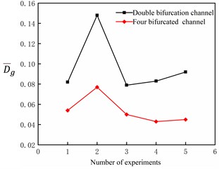
a) Relation between and the number of experiments
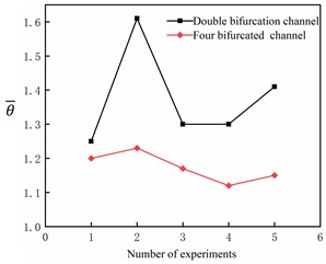
b) Relation between and the number of experiments
Table 2 shows the comparison between the simulation and experimental results. The simulation results are consistent with the experimental results, and the four-bifurcated flow channel structure has better distribution performance. Therefore, the correctness of the simulation is verified experimentally.
Table 2Comparison of simulation and experimental results
Results | Standard flow/quality deviation | Maximum flow/mass ratio |
Simulation results | ||
Experimental results |
5. Conclusions
In this paper, the finite element simulation model is established based on Fluent, and the influence of different flow channels on the uniform distribution performance of the liquid is analyzed. At the same time, the uniform distribution of the shunt plate is tested, and the results show that:
1) The diverting effect of the two diverting disk channels is relatively uniform, and both have good liquid distribution performance. The distribution performance of the four-bifurcated diverter channel is better than that of the double-bifurcated diverter channel, indicating that the distribution performance of liquid can be improved by appropriately increasing the number of the flow channel groups based on the construction theory, and the simulation results are consistent with the experimental results.
2) The four-fork diverter channel has less pressure loss than the double-fork diverter channel, that is, less energy consumption, indicating that the flow channel system with better distribution performance means more energy saving. Therefore, combined with the simulation and experimental results, the final use of the four-fork diverter channel system is the optimal design.
References
-
J. Lee, S. Lorente, A. Bejan, and M. Kim, “Vascular structures with flow uniformity and small resistance,” International Journal of Heat and Mass Transfer, Vol. 52, No. 7-8, pp. 1761–1768, Mar. 2009, https://doi.org/10.1016/j.ijheatmasstransfer.2008.09.027
-
A. Miglani, J. Sharma, S. K. Subramanian, and P. K. Kankar, “The effect of thermal interaction between boiling parallel microchannels on flow distribution,” Lecture Notes in Mechanical Engineering, pp. 483–493, 2023, https://doi.org/10.1007/978-981-19-3379-0_40
-
A. Suneja and S. Roy, “Liquid flow distribution in trickle bed reactors containing trilobed extrusions packed using different techniques,” Results in Engineering, Vol. 17, p. 100704, Mar. 2023, https://doi.org/10.1016/j.rineng.2022.100704
-
D.-U. Kim, J.-T. Kim, S. H. Jeong, and S.-S. Lee, “Structure and arrangement of perforated plates for uniform flow distribution in an electrostatic precipitator,” Journal of the Air and Waste Management Association, Vol. 71, No. 3, pp. 328–338, Mar. 2021, https://doi.org/10.1080/10962247.2020.1808114
-
X. Peng, Z. Liu, C. Qiu, and J. Tan, “Effect of inlet flow maldistribution on the passage arrangement design of multi-stream plate-fin heat exchanger,” Applied Thermal Engineering, Vol. 103, pp. 67–76, Jun. 2016, https://doi.org/10.1016/j.applthermaleng.2016.04.072
-
J. Kim, J. H. Shin, S. Sohn, and S. H. Yoon, “Analysis of non-uniform flow distribution in parallel micro-channels,” Journal of Mechanical Science and Technology, Vol. 33, No. 8, pp. 3859–3864, Aug. 2019, https://doi.org/10.1007/s12206-019-0729-8
-
Zhiwei Fan et al., “Progress in the application of structural theory to engineering,” Chinese Journal of Process Engineering, Vol. 4, pp. 832–839, 2007.
About this article

The authors would like to thank the Science and technology development plan project of Jilin province No. 20190304132YY.
The datasets generated during and/or analyzed during the current study are available from the corresponding author on reasonable request.
The authors declare that they have no conflict of interest.
