Abstract
Aiming at the sealing failure of a water quality monitoring system in a low-temperature environment, a double rubber O-ring sealing structure was designed, and its sealing performance at low temperatures was studied. Finite element software ANSYS constructed the sealing structure, and the change of sealing performance of rubber O-ring in the process of standard temperature installation and low temperature was studied by a two-dimensional axisymmetric model. The results show that the equivalent strain and stress of the sealing structure show an increasing trend during the installation process. With the effect of the medium pressure, the maximum contact stress of the rubber seal ring increases from 2.6285 MPa at 20 ℃ to 2.6657 MPa at 0 ℃. The contact width decreases gradually with the decrease in temperature. With the initial compression rate increase, the maximum contact stress increases significantly. The simulation results show that the double-layer rubber O-ring structure still has good sealing performance at low temperatures.
Highlights
- A double rubber O-ring sealing structure was designed, and its sealing performance at low temperatures was studied.
- The sealing structure was constructed by finite element software ANSYS, and the change of sealing performance of rubber O-ring in the process of normal temperature installation and low temperature was studied by a two-dimensional axisymmetric model.
- The results show that the equivalent strain and stress of the sealing structure show an increasing trend during the installation process. With the effect of the medium pressure, the maximum contact stress of the rubber seal ring increases from 2.6285 MPa at 20 ℃ to 2.6657 MPa at 0 ℃.
- With the increase of the initial compression rate, the maximum contact stress increases significantly. The simulation results show that the double-layer rubber O-ring structure still has good sealing performance at low temperatures.
1. Introduction
In the underwater sealing device, the rubber element plays an important role. Because of its excellent elasticity and compression resistance, the sealing ring rubber may effectively prevent pressure. Therefore, the leakage of the ring is widely used in the sealing field. At the same time, the failures caused by the failure of rubber seals are also increasing, accounting for 30 % of the failures of rubber products [1, 2]. Rubber seals involve theoretical knowledge of materials, mechanical friction, elasticity, liquid erosion, and mechanical manufacturing techniques, which makes it difficult to calculate the deformation and contact pressure of rubber parts under a specific sealing structure. However, with the improvement of computer computing ability, With the development of numerical calculation methods and nonlinear finite element software, researchers have made great progress in dealing with various geometric nonlinear deformations of rubber seal rings under the constitutive model and installation and use conditions, and have made various research achievements. Zhang et al. analyzed the influence of rubber hardness under different pre-compression media pressure on the sealing performance of O-rings, the results show that the lower the ambient temperature is, the greater the shear stress is, and the seal structure is prone to damage and leakage [3]. Li Zhentao et al. used Abaqus to establish the axisymmetric model of the O-ring. Aiming at the effect of different compression rates and ring pressures on the distribution of equivalent stress and contact stress, the failure location of the O-ring material was determined [4]. Liu Jie and L. V. Ren used the Ansys software to establish the O-ring model Analyzed the relationship between the contact stress of rubber O-ring and the compression ratio, hardness, and fluid pressure, and obtained the functional relationship between the contact stress and the compression ratio and the fluid pressure [5].
To study the sealing effect of rubber seals in the cooling process, a double-layer O-ring end cap sealing structure is designed for the large diameter end cap sealing requirements, Ansys software is used to analyze the change of contact stress of rubber seal ring in the process of assembly at room temperature and under the action of pressure from room temperature to low temperature. The influence of structural tightness is evaluated from the aspects of temperature and compression ratio. which provides a reference for the design of the sealing structure of the underwater end cap.
2. Sealing structure of end cap
It is difficult to ensure multi-season sealing at the end cap seal of the existing water surface monitoring platform under the bolt pre-tightening force [6]. The lower plastic material tightens the rubber gasket sealing method, and the plastic shell is prone to crack and seal failure. A new monitoring system and end cap sealing structure are designed. In order to ensure the sealing reliability and increase the sealing contact length, a double rubber O-ring is designed, and the sealing structure is composed of an end cap housing O-ring. The end cap is provided with a groove to place an O-ring, and the through hole of the end cap and the shell is provided with bolts to realize the tight connection between the end cap and the shell. During the installation process, the initial compression of the O-ring is used to achieve the desired sealing effect. The 3D-printed Physical and structural drawings are shown in Fig. 1.
Fig. 1Physical drawing and structural drawing of end cap seal
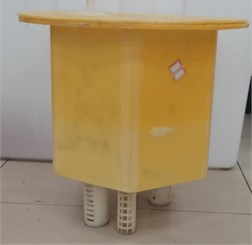
a) Physical picture
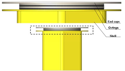
b) Structural drawing
The two-parameter constitutive Mooney-Rivlin model is used to describe the mechanical properties of rubber materials under compression deformation of less than 30 % [7]. Its simplified function expression is shown in Eq. (1):
where is the strain energy density, , is the coefficient of Mooney-Rivlin, , is the first and second strain tensors are invariants [8], where the relationship between stress and strain is shown in Eq. (2):
For the elastic model of rubber material, elastic modulus and Shear modulus have the following relationship with Poisson’s ratio :
Determine rubber material properties according to the rubber compression test, the rubber parameters at different temperatures are shown in Table 1, the remaining material properties are shown in Table 2. In view of the nonlinear characteristics of rubber materials and the solution of rubber contact pressure under a complex environment, the distribution adopts the powerful nonlinear solution function of Ansys and the sealing performance of O-ring changes during the cooling process.
Table 1Second order Mooney-Rivlin constant at different temperatures
Temperature / (℃) | 20 | 10 | 0 |
/ MPa | 1.99 | 2.21 | 2.45 |
/ MPa | 0.70 | 0.62 | 0.50 |
Table 2End cap seal structure material properties
Structure | Density / (kg·m-3) | Elastic modulus / (MPa) | Poisson’s ratio | Coefficient of thermal expansion / (1·℃-1) |
End cap | 1100 | 3120-T | 0.39 | 7.3e-5 |
Shell | 1100 | 3120-T | 0.39 | 7.3e-5 |
Rubber | 1130 | – | 0.49 | 1.75e-4 |
3. Finite element analysis of double rubber ring
3.1. Finite element model
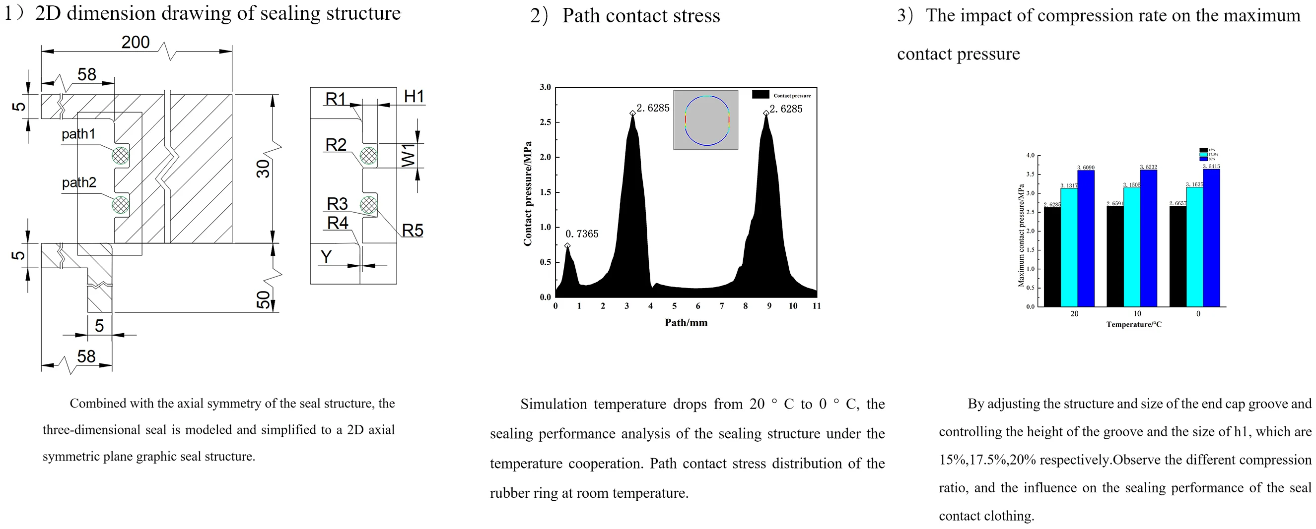
NBR O-ring is a highly nonlinear material, which is difficult to converge in simulation. In order to increase the convergence speed, combined with the axial symmetry of the seal structure, the three-dimensional seal is modeled and simplified to a 2D axial symmetric plane graphic seal structure, as shown in Fig. 2. The key sealing structure dimension parameters in the model are shown in Table 3, and the outer surface of the rubber ring is defined as Path 1 and Path 2. The starting point of the path is located at the inner side of the rubber ring, and it rotates counterclockwise to form a path using the geometric model in Ansys geometry. Use the Split Edges tool to bisect the surface path of the rubber outer ring into a 1/4 circular arc. During initial installation, use the structural dimensions of the end cap and housing to provide a certain amount of compression for O-ring. In the current online sealing structure, the initial compression rate of the O-ring after installation is 15 %.
Fig. 22D dimension drawing of sealing structure
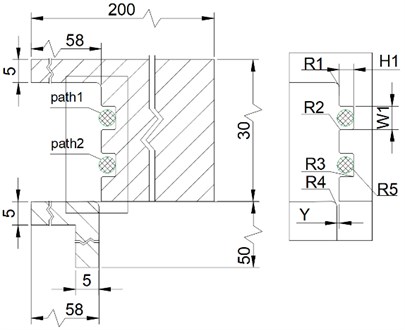
Fig. 3Finite element model of sealing structure
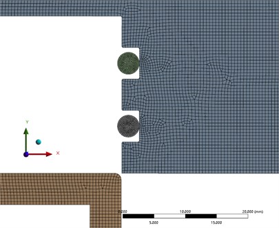
Improving the grid quality is conducive to accurate calculation results. The finite element model of the sealing structure is divided into models. The ABS resin structure in the model is divided into multi areas quadrilateral and triangular mixed grids. The rubber O-ring is divided into default quadrilateral grids. The shell and end cap of the same material is divided into a grid with a size of 0.5 mm for the rubber ring and 0.2 mm for the grid. The total number of grids is 20393, the average quality is 0. 996, and the quality of grid division is good. Local sealing part mesh generation in Fig. 3.
Table 3Key sealing structure dimension
Symbol | Name | Value (mm) |
R1 | Fillet | 1.0 |
R2 | Fillet | 0.2 |
R3 | Fillet | 0.2 |
R4 | Fillet | 1.0 |
R5 | Rubber radius | 1.75 |
H1 | Groove height | 2.9 |
W1 | Groove width | 5.0 |
Y | Interference | 0.1 |
3.2. Boundary conditions and load application
In the numerical calculation, for the installation of the sealing device at room temperature of 20 °C, the boundary conditions are applied as Fig. 4.
1) Constrain all degrees of freedom of the inner edge of the shell.
2) Forced displacement is applied to the end cap direction to realize the compression stroke and pre- compression state of the O-ring.
3) Apply pressure to the upper edge of the O-ring.
Under initial conditions, set the ambient temperature at 20 ℃.
Fig. 4Boundary conditions

4. Sealing performance analysis
At present, for the research and evaluation of rubber sealing performance, the sealing performance is based on the Maximum contact pressure between O-ring and ABS resin structure [9, 10].
4.1. Sealing performance analysis of rubber ring at low temperature
In order to explore the sealing effect of the contact pair between the rubber ring and ABS resin when the ambient temperature drops, After the installation of the O-ring, add 10°, 10°, and 0° temperature nodes to meet the following analysis. When the simulation temperature drops from 20 °C to 0 °C, the sealing performance analysis of the sealing structure under the temperature cooperation. Path contact stress distribution of the rubber ring at room temperature is shown in Fig. 5. The temperature nodes are extracted. The maximum contact pressure and contact width values on the path are shown in Fig. 6. The contact stress cloud of the rubber ring during the cooling process is shown in Fig. 7. It is not difficult to see the contact width of the rubber ring. As the temperature decreases, it shows a downward trend. The maximum contact pressure of the rubber ring shows an upward trend. As the temperature decreases, the structure shrinks. At the same time, the rubber model changes when the temperature decreases. Under the combined action, the maximum contact pressure of the rubber ring shows an upward trend.
Fig. 5Path contact stress
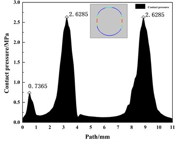
Fig. 6The maximum contact pressure and width values
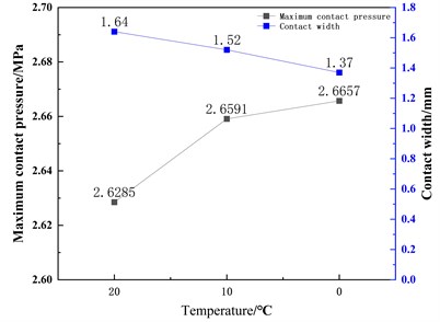
Fig. 7Contact pressure distribution image during cooling
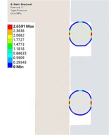
a) 10 ℃ Contact pressure distribution
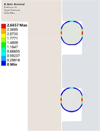
b) 0 ℃ Contact pressure distribution
Fig. 8The impact of compression rate on the maximum contact pressure
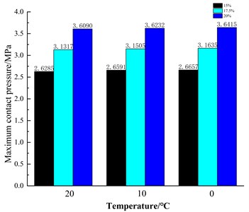
5. Precompression ratio effect
During the installation of the O-ring, a certain amount of pre-compression should be provided for the sealing effect. The rubber ring and compression ratio should be adjusted by adjusting the structure and size of the end cap groove and controlling the height of the groove and the size of , which are 15 %, 17.5 %, and 20 % respectively. Observe the different compression ratio, and the influence on the sealing performance of the seal contact clothing. The expression of the compression ratio. Fig. 8 shows that the impact of compression rate on the maximum contact pressure of rubber is different at different temperatures. Under the effect of different compression rates, the maximum contact pressure increases with the decrease in temperature.
6. Conclusions
1) The designed double-layer rubber O-ring sealing structure can achieve the expected sealing effect while increasing the contact area. 2) The precompression ratio effect has a great impact on the contact pressure. With the increase of the compression rate, the maximum contact pressure shows a significant increase, but the increase of the precompression rate is easy to cause the stress relaxation of the seal ring, causing permanent deformation, leading to seal failure. Therefore, under the premise of ensuring effective seal, it is necessary to reduce. 3) With the decrease of ambient temperature, the , coefficient and elastic model of rubber and ABS resin increase, the double-layer rubber O-ring structure still has good sealing performance at low temperatures.
References
-
X. L. Chang, F. Jiang, and Y. J. Hui, “Environmental failure analysis of rubber sealing components of certain missile,” Equipment Environmental Engineering, Vol. 8, No. 4, pp. 59–62, 2011.
-
X. M. Liu and J. Z. Qi, “Failure analysis and prevention of aircraft rubber parts,” Aviation Maintenance and Engineering, pp. 42–44, 2010.
-
H. Zhang and J. Zhang, “Static and dynamic sealing performance analysis of rubber D-ring based on FEM,” Journal of Failure Analysis and Prevention, Vol. 16, No. 1, pp. 165–172, Feb. 2016, https://doi.org/10.1007/s11668-016-0066-5
-
Z. T. Li et al., “Finite element numerical simulation of the sealing performance of O-ring seals,” Lubrication Engineering, Vol. 36, No. 9, pp. 86–90, 2011.
-
J. F. Liu and X. R. Lv, “Static contact stress analysis of O-ring for slurry shield machine,” Lubrication Engineering, Vol. 44, No. 12, pp. 69–74, 2019.
-
Y. L. Wang, “Study on the design of light buoys used in icy sea of Bohai region,” Jimei University, 2017.
-
X. F. Li and X. X. Yang, “A review of elastic constitutive model for materials,” Elastomer, pp. 50–58, 2005.
-
B. H. Han, “Measurement and Application of rubber material constant based on Mooney-Rivlin model,” Rubber Industry, Vol. 65, No. 5, pp. 499–503, 2018.
-
Q. B. Ren, T. M. Cai, and R. Q. Wang, “Investigation on structure parameters and failure criteria of “O”-type rubber sealing ring,” Solid Rocket Technology, pp. 9–14, 2006.
-
C.-Y. Lee, C.-S. Lin, R.-Q. Jian, and C.-Y. Wen, “Simulation and experimentation on the contact width and pressure distribution of lip seals,” Tribology International, Vol. 39, No. 9, pp. 915–920, Sep. 2006, https://doi.org/10.1016/j.triboint.2005.09.002
About this article

The authors would like to thank the national defense basic Scientific research program of China JCKY2019411B001, the Science and technology development plan project of Jilin province 20210201041GX, the Fund project of Jilin Provincial Department of Education No. JJKH20181124KJ.
The datasets generated during and/or analyzed during the current study are available from the corresponding author on reasonable request.
The authors declare that they have no conflict of interest.
