Abstract
The seismic responses of functionally graded concrete piers with double plastic hinges were studied by finite element (FE) analysis, and especially the formation and effects of double plastic hinges were analyzed in details. The results showed that double plastic hinges in functionally graded concrete piers were made by the graded reinforcement with glass fiber reinforced plastic (GFRP) bars and steel bars. Because GFRP bars have large elastic deformability, double plastic hinges can be stably formed at the bottoms of two grades in turn under different seismic waves. Compared with the traditional reinforced concrete piers, the load bearing capacity, deformation capacity, energy consumption and resisted seismic acceleration of functionally graded concrete piers with double plastic hinges are significantly improved.
1. Introduction
During earthquakes, the reinforced concrete (RC) bridge piers often suffer severe damages. In order to improve the seismic performance of RC piers, the seismic strength of RC piers has been extensively explored [1-2]. Recent studies mainly focus on ductility [3-4] and energy dissipation [5-6] because the RC piers with good deformation and energy dissipation capacity can resist large magnitude of earthquakes.
The deformation and energy dissipation mainly come from the plastic hinge zone of RC pier [7-8]. But in the conventional design of cantilever RC piers, only one plastic hinge is formed at the bottom of the pier [9-12]. The material performance outside the plastic hinge zone cannot be fully utilized, that limits the seismic performance of the RC pier.
At present, few literatures focused on concrete piers with double plastic hinges. Deng et al. [13] strengthened the RC piers by bonding steel plates to the bottom surfaces of the piers to improve the seismic performance, and the hysteretic tests showed that the plastic hinge was transferred to the upper edge of the steel plates from the pier bottom, and then the strengthened piers with double plastic hinges were preliminary analyzed by finite element (FE) simulation.
2. The finite analysis model of the bridge and the graded reinforcement in functionally graded concrete piers
2.1. The bridge
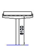
A 2-span simply supported reinforced concrete slab-beam bridge with a pier at the middle is studied, as shown in Fig. 1. The length of each span is 25 m and the height of the pier is 8.1 m. The cross-section of the pier is a 750 mm×750 mm square. Sixteen steel bars with the diameter of 24 mm and sixteen GFRP bars with the diameter of 22 mm were arranged in the concrete pier. As shown in Fig. 2, the steel bars (indicated as red lines) were located in the full length of the pier, while GFRP bars (indicated as blue lines) were graded in height to form two grades of reinforcement. The seismic bearing capacity of functionally graded concrete piers has two grades due to the graded reinforcement. The height of the first grade is the height of GFRP bars, and the second grade is from the top of GFRP bars to the pier top. The mechanical properties of concrete, steel bars and GFRP bars are listed in Table 1.
Fig. 1Schematic diagram of the bridge (unit in mm)

a) Side view
b) Transverse section
Fig. 2Graded reinforcement of the concrete pier (unit in mm)
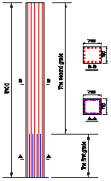
Table 1Mechanical properties of the materials
Parameters | Concrete | Steel bar | GFRP bar |
Elastic modulus | 32 GPa | 200 GPa | 25 GPa |
Yield strength | 477 MPa | ||
Ultimate strength | 48 MPa (Compressive) | 625 MPa | 495 MPa |
Ultimate strain | 0.004 (Compressive) | 0.19 | 0.0198 |
2.2. Finite element model
The finite element (FE) model of the bridge was established using OpenSees [14]. The FE model of the bridge is shown in Fig. 3. The sizes of FE model are the same as the bridge shown in Figs. 1 and 2. The elements of dispBeamColumn were used to model the pier and beams of the bridge. Two elements were used to model each of the beam and eleven elements were used to model the pier. The length of the elements was 375 mm in the plastic hinge zones of the pier, and the length of the elements was slightly longer at other regions of the pier. It is assumed that the masses of the upper beams were concentrated at the mid-spans and the fulcrums, which were 205 tons and 103 tons, respectively. The mass of the pier was concentrated at the 12 nodes according to the length of the elements. The bridge bearings were simulated with the spring elements and the total lateral stiffness of the bearings was 5 kN/mm.
The concrete and steel bars were modelled by Concrete02 constitutive model and Steel02 constitutive model [14], respectively. The Elastic model was used to model GFRP bars [14]. The material properties were the same values in Table 1. The failure strain of the steel bars was adopted as 0.04, and the failure strain of GFRP bars was 0.015 which was about 0.8 times of the ultimate strain.
Fig. 3FE model of the bridge

Five strong seismic waves from PEER Strong Ground Motion Databases [15] were used and the details are shown in Table 2. The five representative seismic waves, including near-fault and far-field earthquakes, have distinctly different spectral characteristics. The seismic waves were input along the transverse bridge direction in FE model to study the seismic responses of the bridge.
Table 2Five strong seismic waves used in this study
Earthquakes | Stations | Peak acceleration (g) | Duration (s) |
EL-CENTRO | USGS STATION 931 | 0.143 | 39 |
KOBE | KAKOGAWA 000 CUE | 0.251 | 41 |
NORTHRIDGE | CDMG STATION 24278 | 0.514 | 40 |
CHICHI | TCU052, N | 0.447 | 90 |
CHRISTCHURCH | PAGES ROAD PUMPING STATION, W | 0.670 | 20 |
3. Double plastics hinges in functionally graded concrete piers
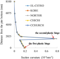
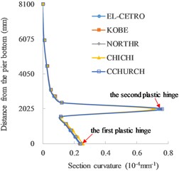
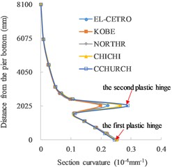
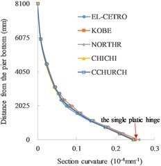
The distributions of section curvature along the pier height under different height of the first grade are shown in Fig. 4.
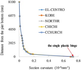
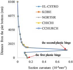
The single plastic hinge occurs at the bottom of the piers without grade (Fig. 4(a) and (f)). As for functionally graded concrete piers (Fig. 4(b)-(e)), double plastic hinges are formed at the bottoms of two grades. When the height of the first grade is 2000 mm, the bottom sections of the first and second grades both reach the ultimate curvature. As a lower height of the first grade, the section curvature at the bottom of the first grade decreases, while the section curvature at the bottom of the second grade reaches the ultimate state, so the final failure occurs at the bottom of the second grade. With the increase in the height of the first grade, the section curvature at the bottom of the second grade decreases rapidly and the damage mainly occurs at the bottom of the first grade with the occurrence of ultimate section curvature. It can be seen that double plastic hinges are formed in functionally graded concrete piers when the height of the first grade is in a wide range from 1125 mm to 2050 mm. The average rates of section curvature to ultimate section curvature in the plastic hinges with different heights of the first grade under five seismic waves are listed in Table 3.
The ultimate strain of GFRP bars is smaller than that of the steel bars, so the ultimate curvature of the sections with GFRP bars and steel bars is lower than that of the sections with only steel bars. The damage in the second grade is more concentrated at the bottom of this grade as indicated by a sharply change in the section curvature distribution curves along the pier height.
Under different seismic waves, the distributions of section curvature are basically the same. The seismic spectrum characteristics slightly influence the formation of double plastic hinges, and double plastic hinges can be stably formed under earthquakes.
Fig. 4Distributions of section curvature along the pier height: a) no grade (0 mm), b) 1125 mm, c) 1600 mm, d) 2000 mm, e) 2050 mm and f) no grade (8100 mm)
a) No grade (0 mm)
b) 1125 mm
c) 1600 mm
d) 2000 mm
e) 2050 mm
f) No grade (8100 mm)
Table 3The average rates of section curvature to ultimate section curvature under five seismic waves
The height of the first grade (mm) | 0 no grade | 1125 | 1600 | 2000 | 2050 | 8100 no grade |
The plastic hinge at the bottom of the first grade (or the bottom of the pier) | 100 % | 61.9 % | 79.5 % | 100 % | 100 % | 100 % |
The plastic hinge at the bottom of the second grade | None | 100 % | 100 % | 100 % | 20.5 % | none |
4. Seismic effects of the functionally graded concrete piers with double plastic hinges
Fig. 5 shows the variation of the seismic shear force at the pier bottom with the height of the first grade. When the height of the first grade is less than 2000 mm, the shear force at the pier bottom increases with the increase in the height of the first grade. And the shear force remains stable when the height of the first grade is above 2000 mm. In the case of NORTHR wave and CHICHI wave, there are obvious increases in the shear force as the height of the first grade at 2000 mm, which may be due to the spectral characteristics of the two seismic waves and the mass distribution of the pier.
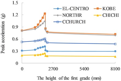
It can be seen in Figs. 6-8, with the increase in the height of the first grade, the ultimate displacement of the pier top, energy consumption and the seismic acceleration that the pier can resist increase, and reach the peak as the height of the first grade at 2000 mm, and then decrease as the height of the first grade further increases.
Compared with the traditional RCpier with single plastic hinge, the average increase of the resisted seismic accelerations of functionally graded concrete piers with double fully-developed plastic hinges is 30.8 %, and KOBE wave has the most increase with 51.8 %, while CCHURCH wave has the least increase with 15.1 %.
Fig. 5Seismic shear force VS the height of the first grade
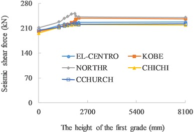
Fig. 6Ultimate displacement VS the height of the first grade
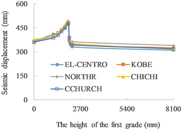
Fig. 7Energy consumption VS the height of the first grade
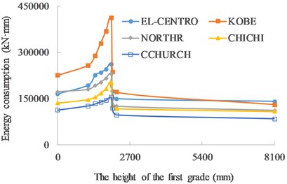
Fig. 8Resisted seismic accelerations VS the height of the first grade
5. Conclusions
Seismic responses of functionally graded concrete piers with double plastic hinges were studied, and the formation and effects of double plastic hinges were analyzed in detail. Conclusions are drawn as below:
1) The seismic bearing capacity of functionally graded concrete piers has two grades due to the graded reinforcement. The steel bars and GFRP bars were located in the first grade at the bottom, while only steel bars were placed in the second grade.
2) Under earthquakes, double plastic hinges can be stably formed in functionally graded concrete piers due to the elastic and large deformation properties of GFRP bars.
3) The seismic shear force, ultimate deformation and energy consumption of functionally graded concrete piers with double plastic hinges are improved, and the seismic accelerations that the piers can resisted is obviously increased.
References
-
G. Cai, Y. Sun, T. Takeuchi, and J. Zhang, “Proposal of a complete seismic shear strength model for circular concrete columns,” Engineering Structures, Vol. 100, pp. 399–409, Oct. 2015, https://doi.org/10.1016/j.engstruct.2015.06.032
-
G. Cai and H. Degée, “Ultimate strengths of FRC rectangular columns subjected to simulated seismic loading: Experimental database and new models,” Archives of Civil and Mechanical Engineering, Vol. 17, No. 1, pp. 96–120, Jan. 2017, https://doi.org/10.1016/j.acme.2016.08.008
-
W. Zhu, J. Jia, J. Gao, and F. Zhang, “Experimental study on steel reinforced high-strength concrete columns under cyclic lateral force and constant axial load,” Engineering Structures, Vol. 125, pp. 191–204, Oct. 2016, https://doi.org/10.1016/j.engstruct.2016.07.018
-
C. Shao et al., “Experimental study on the seismic performance of round-ended hollow piers,” Engineering Structures, Vol. 195, pp. 309–323, Sep. 2019, https://doi.org/10.1016/j.engstruct.2019.05.094
-
Y. Zhang, W. Fan, Y. Zhai, and W. Yuan, “Experimental and numerical investigations on seismic behavior of prefabricated bridge columns with UHPFRC bottom segments,” Journal of Bridge Engineering, Vol. 24, No. 8, p. 04019, Aug. 2019, https://doi.org/10.1061/(asce)be.1943-5592.0001451
-
Z.-K. Cai, Z. Zhou, and Z. Wang, “Influencing factors of residual drifts of precast segmental bridge columns with energy dissipation bars,” Advances in Structural Engineering, Vol. 22, No. 1, pp. 126–140, Jan. 2019, https://doi.org/10.1177/1369433218780545
-
J. Deng, A. Liu, Q. Yu, and G. Peng, “Seismic performances of steel reinforced concrete bridge piers,” Steel and Composite Structures, Vol. 21, No. 3, pp. 661–677, 2016.
-
J. Deng, Z. John Ma, A. Liu, S. Cao, and B. Zhang, “Seismic performance of reinforced concrete bridge columns subjected to combined stresses of compression, bending, shear, and torsion,” Journal of Bridge Engineering, Vol. 22, No. 11, p. 04017, Nov. 2017, https://doi.org/10.1061/(asce)be.1943-5592.0001121
-
J. C. Goodnight, M. J. Kowalsky, and J. M. Nau, “Modified plastic-hinge method for circular RC bridge columns,” Journal of Structural Engineering, Vol. 142, No. 11, p. 04016, Nov. 2016, https://doi.org/10.1061/(asce)st.1943-541x.0001570
-
J. Ge, M. S. Saiidi, and S. Varela, “Computational studies on the seismic response of the state route 99 bridge in Seattle with SMA/ECC plastic hinges,” Frontiers of Structural and Civil Engineering, Vol. 13, No. 1, pp. 149–164, Feb. 2019, https://doi.org/10.1007/s11709-018-0482-6
-
D. Wang, L. Huang, T. Yu, and Z. Wang, “Seismic performance of CFRP-retrofitted large-scale square RC columns with high axial compression ratios,” Journal of Composites for Construction, Vol. 21, No. 5, p. 04017, Oct. 2017, https://doi.org/10.1061/(asce)cc.1943-5614.0000813
-
A. H. M. M. Billah and M. Shahria Alam, “Plastic hinge length of shape memory alloy (SMA) reinforced concrete bridge pier,” Engineering Structures, Vol. 117, pp. 321–331, Jun. 2016, https://doi.org/10.1016/j.engstruct.2016.02.050
-
J. Deng, Z. J. Ma, A. Liu, T. Zhou, and C. You, “Seismic performance of composite column with double plastic hinges,” Composite Structures, Vol. 182, pp. 435–446, Dec. 2017, https://doi.org/10.1016/j.compstruct.2017.09.024
-
The Regents of the University of California and the Pacific Earthquake Engineering Research Center, OpenSees. http://opensees.berkeley.edu/index.php
-
“PEER Strong Ground Motion Databases.” NGA-West2 On-Line Ground-Motion Database, The Pacific Earthquake Engineering Research Center (PEER). https://ngawest2.berkeley.edu/
About this article
The project was financially supported by National Natural Science Foundation of China (No. 51978183, 52178124) and the Natural Science Foundation of Guangdong Province (Grants 2020A1515010231).
The datasets generated during and/or analyzed during the current study are available from the corresponding author on reasonable request.
The authors declare that they have no conflict of interest.
