Abstract
This study investigates the dynamic response of tunnels crossing liquefiable layers, with a focus on the Chongming Line Project of Shanghai Rail Transit. Through numerical analysis using Plaxis2D geotechnical simulation software, the study shows that the UBC3D-PLM constitutive model effectively simulates pore pressure dynamic response in liquefiable layers. Furthermore, the study finds that drainage pile reinforcement on both sides of the tunnel limits liquefaction of liquefiable soil under dynamic load. The rate of EPR accumulation accelerates and the time to reach the peak of EPR ratio shortens with increasing dynamic load intensity. However, the accumulation growth pattern of EPR ratio in liquefiable soil layers remains the same after the dynamic load intensity reaches a certain threshold.
Highlights
- This paper verifies the applicability of the UBC model in the actual engineering of tunnel crossing liquefiable sand soil layers.
- The study demonstrates that drainage pile reinforcement on both sides of the tunnel can effectively restrain liquefaction of liquefiable soil under dynamic load.
- This study presents the effect of different dynamic load intensities on the accumulation and growth pattern of excess pore pressure.
1. Introduction
Tunnel projects face high risk of liquefaction damage when crossing liquefiable strata [1]. Liu et al [2] tested a tunnel structure in saturated sand layer and analyzed acceleration, earth pressure, tunnel strain, and uplift of the sand foundation under seismic. Peng et al. [3] studied the dynamic damage risk of shield tunnels crossing liquefiable layer and analyzed related mechanisms. Koseki et al. [4] studied the pore pressure variation, acceleration response, and uplift displacement of the structure under dynamic loading of sandy soil foundations and underground structures. Yang et al. [5] analyzed the lateral and uplift displacements of a Canadian immersed tube tunnel due to seismic sand liquefaction. The UBC3D-PLM model [6] can accurately describe the liquefaction behavior of saturated soil layers. Anna et al [7] used both the UBC models to simulate the liquefaction of non-cohesive sandy soils and to compare their differences. Demir et al [8] focused on the seismic performance of high modulus columns in liquefiable soils.
This paper shows that the UBC model is effective in dynamic response calculation for tunnel engineering, providing a theoretical basis for protecting against dynamic disasters.
2. Project profile
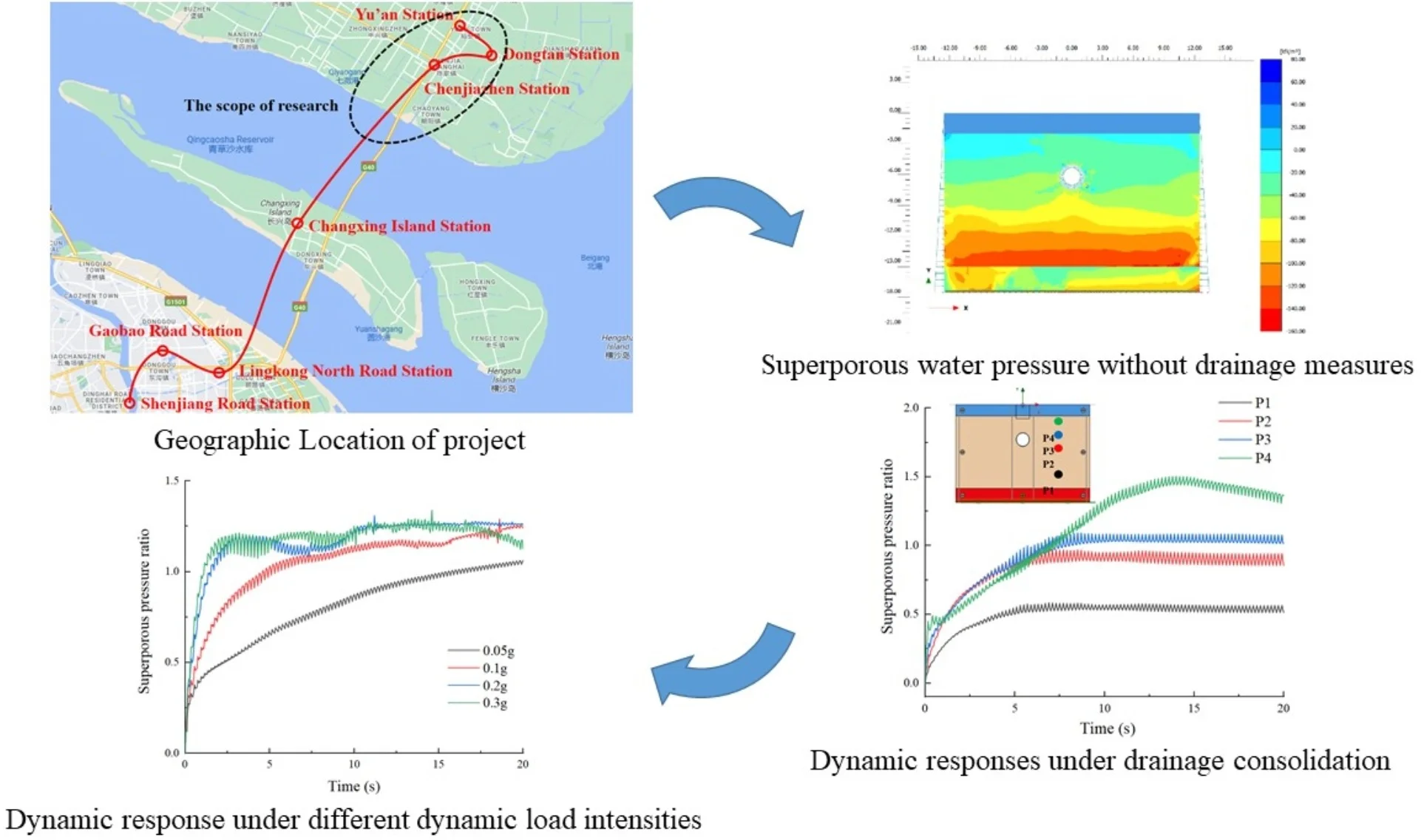
The Chongming Line project includes a 3# size shield conversion shaft, Chenjiazhen Station, Dongtan Station, and the underground interval at the start of the elevated section. A liquefiable sandy chalk layer within 20 m depth of the site that could be damaged and uplifted during seismic activity. The geographic location of the project is shown in Fig. 1.
3. Constitutive model parameters
Numerical simulations are carried out by using Plaxis2D software. The liquefiable layer is simulated using the UBC3D-PLM constitutive model. The main parameters of the materials are shown in Table 1.
The UBC3D-PLM model [7] is a nonlinear elasto-plastic model that accumulates plastic strain and pore water pressure to capture seismic liquefaction. The rest parameters used in the numerical simulations of this constitutive model in this paper are shown in Table 2.
Fig. 1Geographic location of project
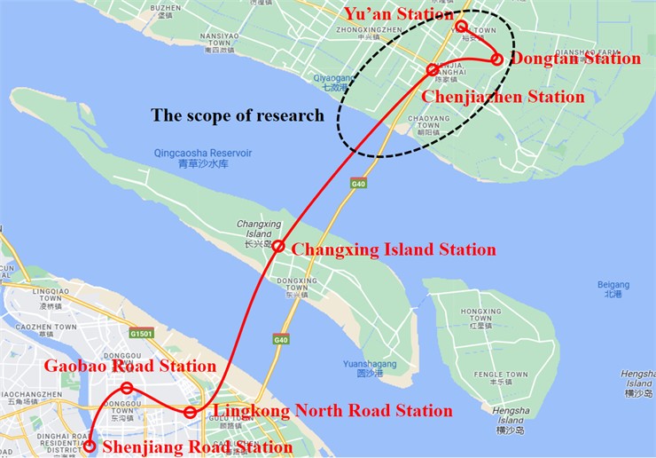
Table 1Main parameters of research materials
Item | , kg/m3 | , MPa | , kPa | , ° | ||
Silt | 19.2 | 0.8 | 20 | 0.33 | 0 | 22 |
Clay | 20 | 0.5 | 50 | 0.33 | 30 | 20 |
Tunnel | 12 | 0.5 | 1000 | 0.38 | / | / |
Table 2Equations for parameters calibration in UBC3D-PLM model
Parameter symbols | Parameters | Equations / Empirical value (EV) |
Relative density (%) | CPT results | |
revisionary SPT hits | ||
shear elasticity modulus | ||
bulk elasticity modulus | ||
plastic shear modulus | ||
frictional angle(constant) | CD tri-axial test results | |
frictional angle(peak) | ||
rate of failure | ||
atmospheric pressure | 100 kPa |
4. Results and analysis
4.1. Dynamic responses under drainage consolidation
Fig. 2 shows the superporous water pressure without drainage measures. The dynamic load at the bottom causes the accumulation of superporous pressure in liquefiable foundation, and the peak value of accumulated superporous pressure increases with depth, following the dynamic response law.
Fig. 2Superporous water pressure without drainage measures
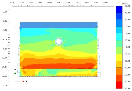
Fig. 3 shows how superporous pressure ratio changes with depth in a liquefiable layer when drainage pile reinforcement is used on both sides. After the reinforcement measures are adopted, the accumulation of larger superporous pressure only occurs in the shallow layer. The pore pressure ratio around the tunnel depth increases slowly.
Fig. 3Superporous pressure ratio with drainage piles reinforcement
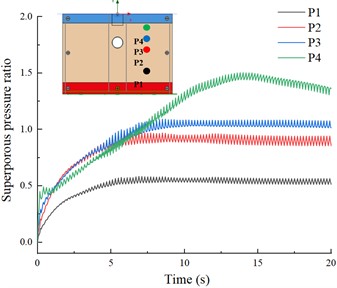
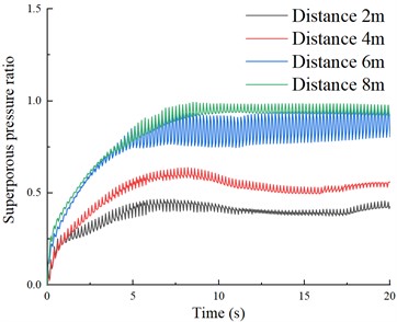
Fig. 4 shows the time travel curves of the superporous pressure at different distances. As the distance from the drainage pile increases, the peak value of the superporous pressure ratio gradually increases (0.4, 0.55, 0.9, and 1). The anti-liquefaction effect of the drainage measures is evident within 4 m (small peak values at 2 m and 4 m, and significant increases at 6 m and 8 m).
Fig. 4Superporous pressure ratio at different distances from drainage pile
4.2. Dynamic response under different dynamic load intensities
Fig. 5 shows the time curves of superporous pressure ratio at different depths under these different dynamic load intensities. The peak of pore pressure ratio in the liquefiable soil was reached at about 20 seconds at each depth for a dynamic load intensity with an acceleration peak of 0.05 g, about 7 seconds with an acceleration peak of 0.1 g, and about 3 seconds with acceleration peaks of 0.2 g and 0.3 g. This implies that different dynamic load intensity conditions mainly affect the accumulation and growth pattern of superporous pressure. After the acceleration peak exceeds 0.2 g, the growth pattern of superporous pressure ratio accumulation in liquefiable layers is basically the same. This indicates that when the dynamic load strength is lower than a certain threshold, the dynamic load strength can hardly cause a peak of superporous pressure in liquefiable layer. However, as the dynamic load strength increases, the time to reach the peak of pore pressure ratio in liquefiable layer becomes shorter.
5. Conclusion
Plaxis2D effectively simulates pore pressure dynamic response in liquefiable layers, and drainage pile reinforcement on both sides of the tunnel effectively restrains liquefaction of the liquefiable layer under dynamic load. Higher power load intensities lead to faster accumulation and peak of superporous pressure ratio. After the power load intensity reaches a certain threshold, the accumulation growth law of superporous pressure ratio is basically the same.
Fig. 5Superporous pressure ratio in different depths
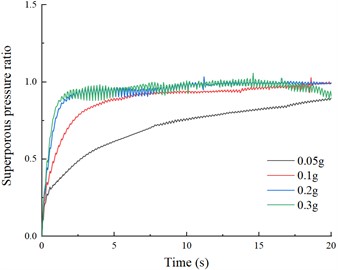
a) P1
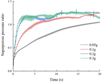
b) P2
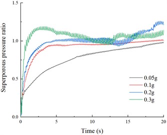
c) P4
References
-
Zheng Gang, Yang Pengbo, Zhou Haizuo, and Zhang Wenbin., “The uplift response of rectangular tunnel in liquefiable soil.,” China Civil Engineering Journal, Vol. 52, pp. 257–264, 2019, https://doi.org/10.15951/j.tmgcxb.2019.s1.033
-
Guanglei Liu et al., “Dynamic centrifuge tests on seismic response of tunnel in saturated sandy foundation.,” Rock and Soil Mechanics, Vol. 29, No. 8, pp. 2070–2076, 2008, https://doi.org/10.16285/j.rsm.2008.08.005
-
Jiaqiang Peng et al., “Analysis on shaking table experiment for shield tunnel through liquefied foundation,” Tunnel Construction, Vol. 38, pp. 60–67, 2018.
-
J. Kosekt, O. Matsuo, and Y. Koga, “Uplift behavior of underground structures caused by liquefaction of surrounding soil during earthquake,” Soils and Foundations, Vol. 37, No. 1, pp. 97–108, Mar. 1997, https://doi.org/10.3208/sandf.37.97
-
P. M. Byrne, S.-S. Park, M. Beaty, M. Sharp, L. Gonzalez, and T. Abdoun, “Numerical modeling of liquefaction and comparison with centrifuge tests,” Canadian Geotechnical Journal, Vol. 41, No. 2, pp. 193–211, Apr. 2004, https://doi.org/10.1139/t03-088
-
H. Puebla, P. M. Byrne, and R. Phillips, “Analysis of CANLEX liquefaction embankments: prototype and centrifuge models,” Canadian Geotechnical Journal, Vol. 34, No. 5, pp. 641–657, Oct. 1997, https://doi.org/10.1139/t97-034
-
A. Borowiec and M. Stanuszek, “Liquefaction mechanism induced by dynamic excitation modeled in Plaxis AE with the use of UBC and MOHR-coulomb constitutive relationships,” Studia Geotechnica et Mechanica, Vol. 38, No. 1, pp. 123–133, Mar. 2016, https://doi.org/10.1515/sgem-2016-0013
-
S. Demir and P. Özener, “Numerical investigation of seismic performance of high modulus columns under earthquake loading,” Earthquake Engineering and Engineering Vibration, Vol. 18, No. 4, pp. 811–822, Oct. 2019, https://doi.org/10.1007/s11803-019-0537-2
About this article

The study is supported by National Natural Science Foundation of China (NSFC) 51379067, 51679072, and Key International/Regional Cooperative Research Project of NSFC 51420105013.
The datasets generated during and/or analyzed during the current study are available from the corresponding author on reasonable request.
The authors declare that they have no conflict of interest.
