Abstract
Large deformation of surrounding rock makes the internal space of a tunnel cannot meet the requirements of normal use after support, even leads to the instability of surrounding rock and destruction of the tunnel structure. In order to optimize the parameters of the primary support to control the deformation of surrounding rock, field tests and numerical simulations are carried out. Based on the engineering geological conditions and the deformation monitoring data of surrounding rock, four important creep parameters of the improved Burgers model are inversed by numerical simulation, considering the creep of surrounding rock in tunnel construction. The results show that it is feasible to use tunnel crown settlement as a control indicator to determine the thickness of shotcrete. Short rock bolts are preferentially used in the tunnel arches, and a combination of long and short rock bolts should be used on the sidewall to control the large deformation of surrounding rock. When the excavation method of upper-lower bench is used in the single-track railway with a relatively large high-span ratio, the horizontal convergence monitoring points of the upper bench are recommended to be set 0.8-0.9 times the height of the upper bench from the tunnel arch crown, and those of the lower bench are recommended to be set 0.6-0.7 times the total height of the upper-lower bench from the tunnel arch crown.
Highlights
- In order to optimize the parameters of the primary support to control the deformation of surrounding rock, field tests and numerical simulations are carried out.
- Based on the engineering geological conditions and the deformation monitoring data of surrounding rock, four important creep parameters of the improved Burgers model are inversed by numerical simulation, considering the creep of surrounding rock in tunnel construction.
- The results show that it is feasible to use tunnel crown settlement as a control indicator to determine the thickness of shotcrete.
1. Introduction
Large deformation of surrounding rock often occurs in tunnel construction [1-3] (shown in Table 1). Large deformation of surrounding rock makes the internal space of the tunnel cannot meet the requirements of normal use after support. If the deformation of surrounding rock is too large to be controlled, the tunnel structure will be destroyed, such as the Shiziyuan tunnel in the Chengdu-Lanzhou railway [4], and even the collapse of tunnel, such as the Jiubao tunnel of the Zhangjiakou-Jiningrailway [5]. In view of the large deformation of surrounding rock, the guiding principle in engineering is “combining support and stress release, focusing on support and strengthening the longitudinal lining of the tunnel” [6]. Common measures to control the large deformation of surrounding rock include optimizing the structure form of tunnel section, adding reserved deformation, strengthening the support, layering the support, radial grouting [7], strengthening the locking foot bolt, closing the lining in time, dynamic reinforcement [8], and adopting the double-layer support [9]. These measures will increase the construction process and project cost, and extend the construction time to varying degrees. Large deformations of the tunnel surrounding rock are related to engineering geology, groundwater, in-situ stress, and construction methods [10]. Based on the variation law of the deformation of tunnel surrounding rock with time, the specific deformation characteristics of tunnel surrounding rock are obtained. Taking the tunnel excavation sections, common support measures and excavation construction methods as the basic conditions, the parameters of the primary support and the support time of the secondary lining are optimized and analyzed to achieve reasonable control of the large deformation of surrounding rock at minimum cost.
Table 1Disasters of large deformation tunnel in tunnel construction
Number | Country | Tunnel name | Maximum displacement of the primary support (cm) | Maximum crown settlement (cm) |
1 | Austria | Tauern road tunnel [1] | 120 | – |
2 | Austria | Arlberg road tunnel [1] | 35 | 20 |
3 | Japan | Enasan tunnel [1] | 56 | 94 |
4 | China | Jiazhuqing road railway tunnel [1] | 160 | 240 |
5 | China | Muzhailing railway tunnel [2] | – | 150 |
6 | China | Wushaoling railway tunnel [3] | 120.9 | 105.3 |
Aiming at the large deformation of the surrounding rock of a single-track railway tunnel, the CIVIS constitutive model (visco-elastic-plastic model)is used based on the deformation law of surrounding rock. The parameters of the CIVIS model are inversed based on the monitoring data of deformation. Considering the time effect of construction processes during the construction period, reasonable support parameters, such as the thickness of shotcrete, the length of rock bolts, the spacing of rock bolts and the support time of the secondary lining are analyzed. The positions of the horizontal convergence monitoring point are studied.
2. Material and research method
2.1. Project background
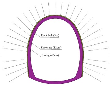
A tunnel with a length of 1690 m and a maximum buried depth of 190 m is studied. The tunnel is excavated by the upper-lower bench method. The support of rock bolts and shotcrete is used in tunnel construction, and large deformation of the surrounding rock occurs. One part of the tunnel, where the supporting structure includes shotcrete, rock bolts and reinforcing mesh (shown in Fig. 1), is studied. Parameters of the supporting structures are shown in Table 2.
Table 2Parameters of the supporting structures
C25 Shotcrete | Reinforcing mesh | Rock bolt | C30 Concrete | ||
Thickness (cm) | Diameter of steel bar (mm) | Spacing (cm) | Length (m) | Spacing (m) | Thickness (cm) |
12 | 6 | 25×25 | 3 | 1.2×1.2 | 40 |
Fig. 1Supporting structures of the studied tunnel
2.1.1. Engineering geology
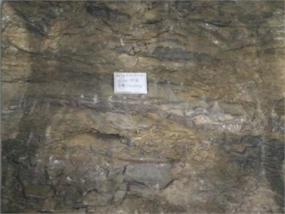
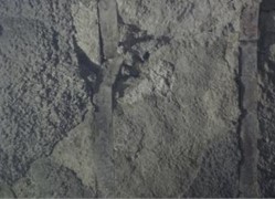
According to the code for design on tunnel of railway (TB 10003-2016) issued by China, the tunnel length of surrounding rock of grade Ⅳ accounts for 76 % of the tunnel length, and that of grade Ⅴ accounts for 24 % of the tunnel length. The surrounding rock is composed of quartz sandstone, silty slate and carbonaceous sericite slate (shown in Fig. 2). Silky slate and quartz sandstone are interbedded, and the layers are not tightly bonded. There is a small amount of yellow silt in the layers. There are a large number of rock joints and fissures in the surrounding rock, and the self-stability of the surrounding rock is poor.
Fig. 2Typical surrounding rock of tunnel face (Photographed by Rui Qu, Jiedexiu tunnel, 2016)
2.1.2. Large deformation of surrounding rock
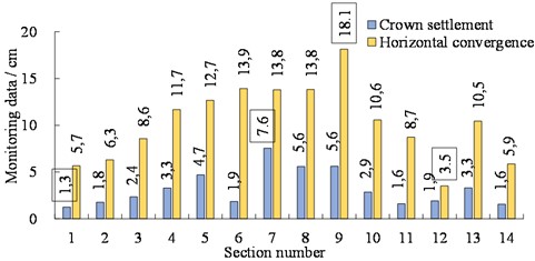
In tunnel construction, 76 % of the tunnel length shows large deformation of the surrounding rock. Parts of the final values of the tunnel crown settlement and horizontal convergence (monitoring data) are listed in Fig. 3. The average value, minimum value and maximum value of the tunnel crown settlement are 3.2 cm, 1.3 cm and 7.6 cm, respectively. The average value, minimum value and maximum value of tunnel horizontal convergence are 10.3 cm, 3.5 cm and 18.1 cm, respectively. However, the allowable deformation of the surrounding rock in these tunnel sections is only 3-5 cm. To this end, the excessive deformation of the surrounding rock results in the intrusion of shotcrete into the position of the tunnel lining.
Fig. 3Monitoring data of tunnel crown settlement and horizontal convergence
2.1.3. Damage of large deformation
There is a lot of damage in this tunnel where large deformation occurs (shown in Fig. 4). Due to the cracked shotcrete, the surrounding rock and the primary support are unstable. Steel arches are usually distorted, so that the first supporting system could bear fewer loads than before. If the tunnel is buried at a small depth, a large number of large cracks will appear in the ground. These are only parts of adverse consequences caused by large deformation of the surrounding rock. It is necessary to study some effective methods to prevent the large deformation of surrounding rock.
Fig. 4Damage caused by large deformations of surrounding rock (photographed by Rui Qu, Jiedexiu tunnel, 2016)
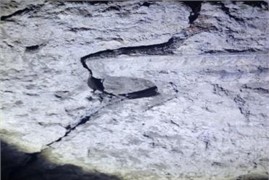
a) Cracks of shotcrete
b) Distorted steel arch
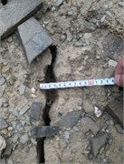
c) Ground cracks
2.2. Creep law
2.2.1. Introduction of creep model
There are many constitutive models that can characterize creep in rock masses, such as Kelvin model, Maxwell model, Generalized Kelvin model, Generalized Maxwell model, Nishihara model, Burgers model, Bingham model and improved Burgers creep model (CIVIS model) [11]. In order to reflect the whole process of rock rheology and simulate the visco-elastic-plastic properties of rocks, the improved Burgers creep model [14] is used for calculation and analysis.
The improved Burgers model [12-13] is composed of Maxwell model, Kelvin model and M-C (Mohr-Coulomb) plastic element in series, as shown in Fig. 5. The improved Burgers model can reflect the viscoelastic plastic deviator behavior and the elastic-plastic volume behavior. The plastic behavior is realized by the Mohr-Coulomb criterion.
Fig. 5The improved Burgers model
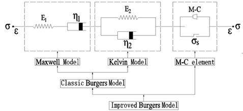
In the improved Burgers model, there are two cases:
(1) When ( is the yield stress of the Mohr-Coulomb criterion), the strain of the M-C element is zero, and the improved Burgers model becomes the classic Burgers model. That is, the Maxwell model and the Kelvin model are connected in series. When the rock is subjected to axial stress , the axial strain can be expressed as follows:
Assuming that all parameters of the model are independent of time under the action of , when the time is long enough, the strain rate is constant, and the creep curve is a straight line (asymptote of the stable creep curve). At this time, the creep relationship is as follows:
where is the bulk modulus of the sample; is the elastic modulus of the Kelvin model; is the elastic modulus of the Maxwell model; is the delayed elastic rate coefficient of the Kelvin model, and is the coefficient of viscous flow rate of the Maxwell model.
(2) When , the strain of the M-C element completely obeys the plastic flow of the Mohr-Coulomb criterion. The deviator behavior of the improved Burgers model is expressed as follows:
The total strain rate:
Kelvin:
Maxwell:
M-C components:
where can be expressed as follows:
The volume behavior is determined by the following equation:
The yield envelope of the Mohr-coulomb criterion includes two criteria: shear and tension. The yield criterion is , which can be expressed using the principal axis stress space formula.
The shear yield:
The tensile yield:
where is the cohesion; is the internal friction angle, and is the tensile strength, and are the maximum and minimum principal stresses, respectively (positive for tension, negative for pressure).
2.2.2. Numerical model and construction steps
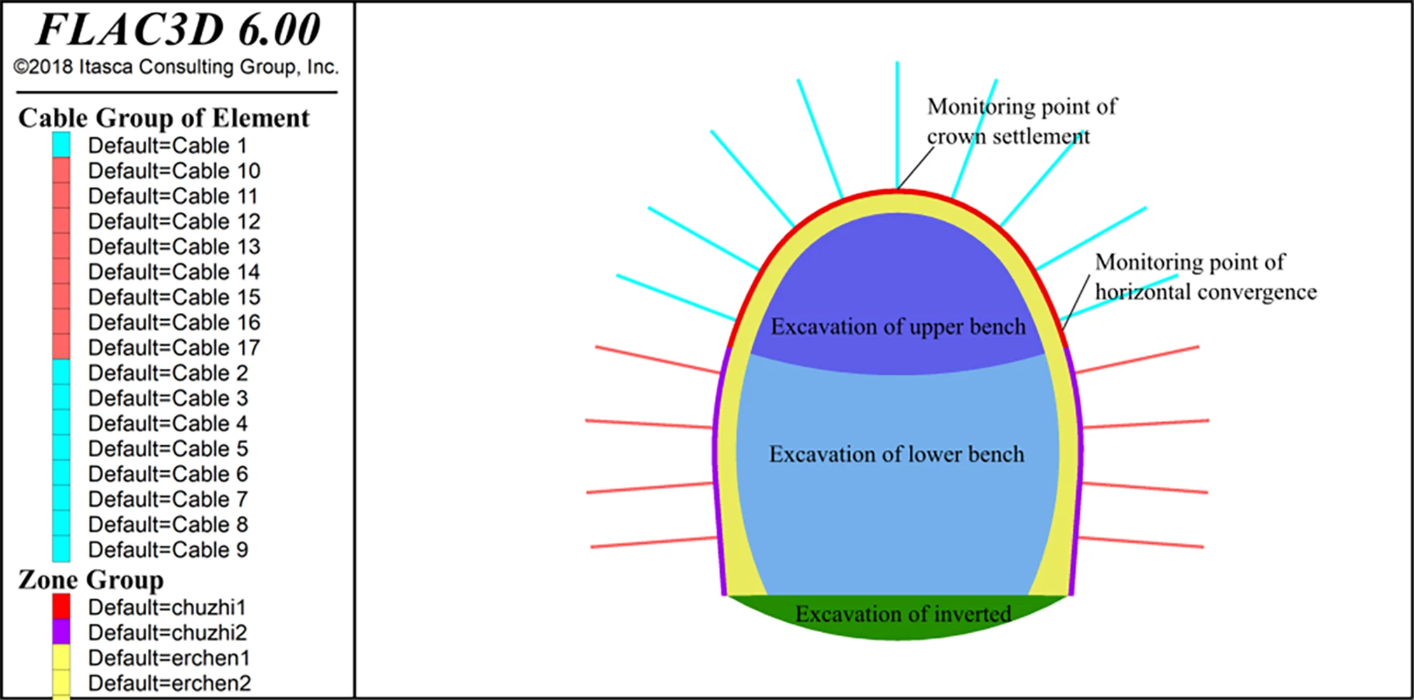
In this paper, the 9th section of the background engineering tunnel is taken as the prototype, and the numerical simulation is carried out with FLAC3D software. The size of the numerical model is 120 m (height) × 65 m (width) × 1 m (thickness) with a total of 13556 elements and 27574 nodes. The solid element is used for the surrounding rock, the inverted arch and the secondary lining. The shell element is used for shotcrete, and the cable element is used for the rock bolt. The improved Burgers creep model is adopted to simulate the characteristics of surrounding rock, described by formula (1)-(11). The boundary condition is that the top of the model is a free boundary; the bottom boundary of the model is constrained by vertical zero displacements, and the front, back, left and right boundaries of the model are constrained by normal horizontal zero displacements. The calculation parameters are shown in Table 3, and the calculation model is shown in Fig. 6.
Table 3Physical and mechanical parameters
Number | Material | Density (kg/m3) | Elastic modulus (GPa) | Poisson’s ratio | Internal friction angle (°) | Cohesion (kPa) |
1 | surrounding rock | 2200 | 4.0 | 0.33 | 55.0 | 500.0 |
2 | C25 concrete | 2300 | 23 | 0.2 | - | - |
3 | C30 reinforced concrete | 2300 | 31 | 0.2 | - | - |
Fig. 6Numerical model
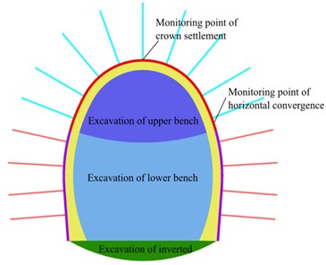
Table 4Simulation steps of tunnel construction
Number | Construction steps | Time (day) | Number | Construction steps | Time (day) |
1 | Gravitational stress field | 0 | 6 | Support of lower bench | 0 |
2 | Excavation of upper bench | 0 | 7 | Creep | 11 |
3 | Support of upper bench | 0 | 8 | Excavation of inverted arch | 0 |
4 | Creep | 7 | 9 | Support of inverted arch and low wall | 0 |
5 | Excavation of lower bench | 0 | 10 | Creep | 55 |
The tunnel of the background project is constructed using the bench excavation method (Fig. 6). The whole section of the tunnel is excavated in three layers, including the upper bench, the lower bench and the inverted arch. Each excavation part includes the space occupied by the primary support and the secondary lining. Shotcrete and rock bolts of the primary support are constructed in two steps after the excavation of the upper bench and the lower bench respectively. The secondary lining is constructed after the completion of the primary support and the inverted arch. The large deformation of the surrounding rock of the background project occurs in tunnel construction. Since creep is time-dependent, the interval time in the construction step is taken into account, not the actual time of the construction steps. The construction steps of this numerical simulation are shown in Table 4.
3. Results
3.1. Parameter inversion of improved Burgers model
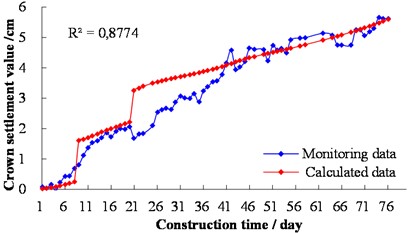
According to the maximum radial displacement of the unlined tunnel at different times [14] and the monitoring data of section 9 of the tunnel background project, the initial creep parameters of the Burgers model are obtained by fitting. The initial creep parameters are 4.0×10⁸ Pa, 4.3×10⁸ Pa/s, 9.0×10⁹ Pa, and 6.0×10⁸ Pa/s, respectively. Based on the initial creep parameters of the Burgers model and the calculated parameters in Table 3, the variation of the tunnel crown settlement with construction steps and time is taken as the reference for the inversion of surrounding rock parameters. The tunnel crown settlement values are called calculated data, obtained by formula (12). Comparing the calculated and monitoring values of the tunnel crown settlement, when the parameters of the Burgers model are 3.0×10⁹ Pa, 1.0×10⁹ Pa/s, 1.185×10⁸ Pa, and 8.5×10⁶ Pa/s respectively, the maximum correlation coefficient is 0.88. In addition to the difference between the maximum instantaneous deformation generated by each excavation step and the monitoring value, the deformation value and the development trend generated by the rheological model over a long period of time are basically consistent with the monitoring value (shown in Fig. 7):
In this way, the creep parameters of the Burgers model that truly reflects the rheological properties of the surrounding rock of the background project are obtained. In the subsequent analysis, numerical simulation and analysis are carried out based on the creep parameters of the Burgers model inverted.
Fig. 7Comparison of monitoring and calculated values of crown settlement
3.2. Optimization of primary support parameters
According to the theory for the modern support of rock bolts and shotcrete, and the construction core of the New Austrian Tunneling Method [15], the stiffness of the primary support should not be too large. The surrounding rock should be allowed to deform and release stresses, but the deformation of surrounding rock should not be allowed to develop indefinitely. According to the references [16-18], the deformation of tunnels is largely affected by parameters such as shotcrete thickness, anchor rod length and spacing. These parameters are analyzed as below.
3.2.1. Influence of shotcrete thickness
Shotcrete is one of the main components of primary support. Shotcrete and surrounding rock are tightly combined and deformed together. Due to the fact that the elastic modulus of sprayed concrete is greater than that of surrounding rock, the thickness of sprayed concrete will change its stiffness. For the same grade of concrete, concrete thickness is one of the important parameters to control the deformation of surrounding rock [19]. Here, five cases of shotcrete thickness of 10 cm, 15 cm, 20 cm, 25 cm and 28 cm are analyzed.
Tunnel crown settlement is one of the important indicators to monitor the deformation of surrounding rock. For different shotcrete thicknesses, the curve of the tunnel crown settlement with construction steps and time is shown in Fig. 8. The excavation of the lower bench and the inverted arch leads to large instantaneous deformation of the tunnel crown settlement, and that of the lower bench leads to an increase of 15.8 cm of the tunnel crown settlement. The tunnel crown settlement varies greatly at different construction steps. The tunnel crown settlement is the largest when the thickness of the primary support is 25 cm and 28 cm before the end of the lower step support, and the other three cases are similar. After the lower bench support and before the secondary lining is completed, the tunnel crown settlement is minimal when the thickness of shotcrete is 20 cm.
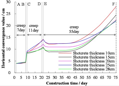
Horizontal convergence is another important indicator to monitor the deformation of surrounding rock. When different thicknesses of shotcrete are used, the curves of the horizontal convergence of the upper bench with construction steps and time are shown in Fig. 9. The excavation of the lower bench leads to a large instantaneous deformation of the horizontal convergence of the upper bench, and that of the lower bench leads to an increase of 41.0 cm in the horizontal convergence of the upper bench. The excavation of the inverted arch has little effect on the horizontal convergence of the upper bench. The horizontal convergence of the upper bench in five cases remains largely unchanged until the end of the lower step support. From the end of the lower bench support to the end of the inverted arch support, the horizontal convergence of the upper bench at the five cases changes greatly. The horizontal convergence of the upper bench is the largest when the thickness of shotcrete is 10 cm and 25 cm, and that of the upper bench is the smallest when the thickness of shotcrete is 15 cm and 28 cm.
Fig. 8Variation of crown settlement for different shotcrete thicknesses with time in tunnel construction. Note: A – the end of the primary support of the upper bench; B – the end of the excavation of the lower bench; C – the end of the primary support of the lower bench; D – the end of the excavation of the inverted arch; E – the end of the support of the inverted arch, and F – the beginning of secondary lining
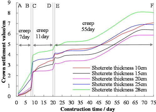
The variation law of shotcrete thicknesses on the tunnel crown settlement and the horizontal convergence of the upper bench is different. When the tunnel crown settlement is used as a control indicator, the optimum thickness of shotcrete is 20 cm. The horizontal convergence of the upper bench enters the unstable creeping stage in the later stage. When the thickness of shotcrete is greater than or equal to 20 cm, the maximum horizontal convergence of the upper bench has little difference. Theoretically, there is an optimal thickness of shotcrete to control the deformation of surrounding rock. For the analysis section of the background engineering tunnel, a shotcrete thickness of 20 cm is the most reasonable.
Fig. 9Variation of horizontal convergence of the upper bench for different shotcrete thicknesses with time in tunnel construction. Note: A – the end of the primary support of the upper bench; B – the end of the excavation of the lower bench; C – the end of the primary support of the lower bench; D – the end of the excavation of the inverted arch; E – the end of the support of the inverted arch, and F – the beginning of secondary lining
3.2.2. Influence of rock bolt
Rock bolt is one of the important components of tunnel primary support, which can reinforce the loose zone, improve the bearing capacity of the surrounding rock from the inside, reduce deformation, and stabilize the surrounding rock [20]. Here, the effects of rock bolt with the lengths of 3 m, 5 m, 7 m and 10 m on the deformation of surrounding rock is analyzed. In addition, the effect of long and short rock bolts [21] on the deformation of surrounding rock is also analyzed, which is composed of a long rock bolt and a short rock bolt spacing arrangement. One combination has a rock bolt length of 5 m and 3 m, and the other combination is 10 m and 5 m.
The tunnel crown settlement with the combined support of long and short rock bolts is significantly greater than that of the uncombined support of rock bolts (Fig. 10). When the creep of the surrounding rock in construction is taken into account, increasing the length of rock bolts does not have an obvious effect on the control of tunnel crown settlement. When the length of rock bolts is 3 m, 5 m, 7 m and 10 m, respectively, the tunnel crown settlement before the secondary lining support is 5.9 cm, 6.4 cm, 6.6 cm and 6.4 cm, respectively. The combined support of long and short rock bolts is an effective method to control horizontal convergence. When the rock bolt lengths of the combined support are 5 m and 3 m, the horizontal convergence of the upper bench before the secondary lining support is 19.0 cm. When the rock bolt lengths of the combined support are 10 m and 5 m, the horizontal convergence of the upper bench before the secondary lining support is 15.0 cm. Different support parameters of rock bolts thus should be adopted for the arch and side wall of the tunnel respectively. For the tunnel analysis section of the background project, it is more reasonable to use 3 m bolt support in the tunnel arch and a combination of 10 m and 5 m bolt support on the tunnel sidewall.
Fig. 10Variation of crown settlement for different rock bolt lengths with time in tunnel construction. Note: A – the end of the primary support of the upper bench; B – the end of the excavation of the lower bench; C – the end of the primary support of the lower bench; D – the end of the excavation of the inverted arch; E – the end of the support of the inverted arch, and F – the beginning of secondary lining
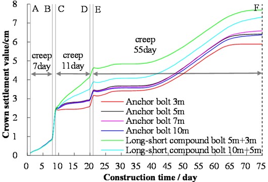
Fig. 11Variation of horizontal convergence of the upper bench for different rock bolt lengths with time in tunnel construction. Note: A – the end of the primary support of the upper bench; B – the end of the excavation of the lower bench; C – the end of the primary support of the lower bench; D – the end of the excavation of the inverted arch; E – the end of the support of the inverted arch, and F – the beginning of secondary lining

Based on the theory of the New Austrian Tunneling Method, the tunnel support should allow some deformation of the surrounding rock, while excessive deformation of surrounding rock should be prevented. Since the construction of the primary support has been completed, only the timely construction of the secondary lining can prevent excessive deformation of the surrounding rock. As shown in Fig. 8-Fig. 11, after 25 days since the end of the primary support of the upper step, the settlement of the tunnel crown and the horizontal convergence of the waist of the upper step have hardly changed. The deformation is stable until 40 days or so, and then the deformation increase more and more. The secondary lining needs some strength to bear load. Thus, it is better to finish the secondary lining as soon as possible. Based on this and time saving, the best time for secondary lining construction should be about 25 days after the end of the primary support of the upper bench.
3.2.3. Position of maximum horizontal convergence
Fig. 12 shows the horizontal convergence along the tunnel excavation contour profile. It can be seen from Fig. 12(a) that the maximum horizontal convergence is 1.97 cm when the excavation of the upper bench is completed. The vertical distance between the position of the maximum horizontal convergence and the tunnel crown is 2.8 m, and the ratio of this vertical distance to the excavation height of the upper bench is 0.83. When the excavation of the lower bench is completed, the maximum horizontal convergence within the upper bench is 4.32 cm. The vertical distance between the position of the maximum horizontal convergence in the upper bench and the tunnel crown is 3.09 m, and the ratio of this vertical distance to the excavation height of the upper bench is 0.91. With the excavation of the lower bench, the position of the maximum horizontal convergence moves down. The horizontal convergence is relatively large in the range of 0.8-0.9 times the height of the upper bench from the tunnel arch crown it can represent the maximum horizontal convergence in the range of the upper bench. Due to the complexity of tunnel construction, when the upper-lower bench is used for excavation, it is reasonable to set the horizontal convergence monitoring points of the upper bench 0.8-0.9 times the height of the upper bench from the tunnel arch crown according to the actual conditions. After the excavation of the lower bench, the maximum horizontal convergence is 4.80 cm. The vertical distance between the maximum horizontal convergence position of the upper-lower bench and the tunnel crown is 5.83 m. The ratio of this vertical distance to the excavation height of the upper-lower bench is 0.67. It can be seen from Fig. 12(b) that the monitoring points for horizontal convergence of the lower bench should be set 0.6-0.7 times the total height of the upper-lower bench from the tunnel arch crown.
Fig. 12Variation of horizontal convergence along the tunnel excavation contour profile
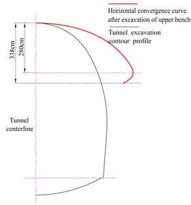
a) Horizontal convergence curve after excavation of the upper bench

b) Horizontal convergence curve after excavation of the lower bench
4. Conclusions
Based on the engineering geological conditions and the deformation test data of tunnel surrounding rock of the background project, four important creep parameters of the Mohr-Coulomb-Burgers constructive model are inversed by FLAC software. On this basis, considering the completion time of construction steps in tunnel construction, the deformation of the surrounding rock is analyzed. The influence of different design parameters of shotcrete and rock bolts on the deformation of surrounding rock is studied. The main conclusions are as follows:
1) Taking the monitoring values of the tunnel crown settlement as the target, the relatively accurate calculation parameters of surrounding rock are obtained by inversion. The correlation coefficient between the calculated values of the inversion parameters and the monitoring values can reach 0.88. Inversion parameters can characterize the elastic-plastic and creep parameters of surrounding rock for section analysis of the background project. Here, it is assumed that the surrounding rock is a continuous medium. However, the structural plane opening deformation and loose area slip caused by tunnel excavation are discontinuous. This leads to a large maximum error between the calculated value and the monitoring value in the construction steps, while the calculated value in the creep stage is basically consistent with the monitoring values.
2) Shotcrete is a flexible support that allows the deformation of surrounding rock to control harmful deformation. Although the effect of shotcrete thickness on the tunnel crown settlement and the horizontal convergence of the upper bench is different, it is feasible to determine the shotcrete thickness using the tunnel crown settlement as a control indicator. It is reasonable for the tunnel arch and side wall to have different bolt support parameters. Short rock bolts are preferentially used for tunnel arches, and a combination of long and short rock bolts is used on the sidewall to control the large deformation of surrounding rock.
3) For the single-track railway tunnel with a relatively large high-span ratio of 1.23, when the upper-lower bench excavation is used for construction, the horizontal convergence of each bench needs to be monitored after excavation in accordance with the requirements of the New Austrian Tunneling Method. The monitoring points for horizontal convergence of the upper bench are recommended to be set 0.8-0.9 times the height of the upper bench from the tunnel arch crown, and that of the lower bench are recommended to be set 0.6-0.7 times the total height of the upper-lower bench from the tunnel arch crown.
References
-
B. Wang, J. Wang, D.-X. Wu, J.-Q. Xu, and Y.-D. Zhao, “Discussion on the application of yielding support technology for large deformation of soft-rock tunnel,” Journal of Highway and Transportation Research and Development (English Edition), Vol. 9, No. 3, pp. 69–77, Sep. 2015, https://doi.org/10.1061/jhtrcq.0000459
-
M. Zhang, Z. J. He, M. Q. Zhang, G. Z. Xiao, and C. M. Ren, “Design and construction technologies to control the deformation of a soft rock tunnel with high ground stress,” Modern Tunnelling Technology, Vol. 49, No. 6, pp. 13–22, 2012, https://doi.org/10.13807/j.cnki.mtt.2012.06.005
-
G. L. Li and Y. Q. Zhu, “Control technology for large deformation of highland stressed weak rock in Wushaoling tunnel,” Journal of Railway Engineering Society, No. 3, pp. 54–59, 2008.
-
T. C. Yu, “Study on large deformation control technology of tunnel in soft rock,” China Civil Engineering Journal, Vol. 50, pp. 112–117, 2017, https://doi.org/10.15951/j.tmgcxb.2017.s2.018
-
X. Li and Z. F. Liu, “Reason analysis and treatment measures of large deformation of primary support of Jiubao tunnel on Zhangiakou-Jining railway when passing through fault fracture zone,” Railway Standard Design, Vol. 58, No. 5, pp. 109–112, 2014, https://doi.org/10.13238/j.issn.1004-2954.2014.05.025
-
Q. H. Deng, “Deformation law and control measures in soft rock tunnel with large deformation,” Construction Technology, Vol. 45, No. 17, pp. 124–126, 2016.
-
L. H. Ran, “Mechanism and control technology of large deformation of surrounding rock in Yuntunpu tunnel,” Railway Engineering, Vol. 61, No. 7, pp. 62–66, 2021.
-
M. Q. Zhang, H. J. Huang, Z. J. He, C. M. Ren, and W. Q. Zhang, “Technology for control of deformation of high stress soft rock tunnel with release-constraint balancing method,” Journal of Railway Engineering Society, Vol. 30, No. 3, pp. 50–57, 2013.
-
G. Y. Ma, C. He, Z. Q. Chen, C. C. Ma, W. B. Yang, and X. H. Lan, “Research on mechanical properties of double primary support method of deep buried tunnel based on damage evolution rheological model,” Journal of Central South University (Science and Technology), Vol. 52, No. 8, pp. 2897–2909, 2021.
-
H. Wu, F. Fan, X. Yang, Z. Wang, J. Lai, and Y. Xie, “Large deformation characteristics and treatment effect for deep bias tunnel in broken phyllite: A case study,” Engineering Failure Analysis, Vol. 135, p. 106045, May 2022, https://doi.org/10.1016/j.engfailanal.2022.106045
-
C. Paraskevopoulou and M. Diederichs, “Analysis of time-dependent deformation in tunnels using the convergence-confinement method,” Tunnelling and Underground Space Technology, Vol. 71, No. 71, pp. 62–80, Jan. 2018, https://doi.org/10.1016/j.tust.2017.07.001
-
H. Tran Manh, J. Sulem, D. Subrin, and D. Billaux, “Anisotropic time-dependent modeling of tunnel excavation in squeezing ground,” Rock Mechanics and Rock Engineering, Vol. 48, No. 6, pp. 2301–2317, Nov. 2015, https://doi.org/10.1007/s00603-015-0717-y
-
H.-C. Wang, W.-H. Zhao, D.-S. Sun, and B.-B. Guo, “Visco-elastop-lastic constitutive relationship of rock and modified Burgers creep model,” Chinese Journal of Geophysics, Vol. 55, No. 6, pp. 733–741, Nov. 2012, https://doi.org/10.1002/cjg2.1767
-
K. Wu, Z. Shao, and S. Qin, “An analytical design method for ductile support structures in squeezing tunnels,” Archives of Civil and Mechanical Engineering, Vol. 20, No. 3, pp. 1–13, Sep. 2020, https://doi.org/10.1007/s43452-020-00096-0
-
J. Golser, M. Keuschnig, and F. P. Weichenberger, “NATM – Review and Outlook,” Geomechanics and Tunnelling, Vol. 13, No. 5, pp. 466–474, Oct. 2020, https://doi.org/10.1002/geot.202000015
-
Y. C. Ma and L. N. Ma, “Research on tunnel deformation control measures and excavation method based on Midas /GTS,” Highway Engineering, Vol. 45, No. 5, pp. 149–155, 2020, https://doi.org/10.19782/j.cnki.1674-0610.2020.05.025
-
X. K. Bao, M. H. Shi, Y. H. Lei, W. Zhang, and S. Y. Wang, “Study on deformation law and supporting countermeasures of Huajiaoqing soft rock tunnel,” Journal of Chongqing Jiaotong University (Natural Science), 2023.
-
S. J. Zhang, Y. P. Zhong, Y. J. Qi, and S. K. Liu, “Study on deformation and stress characteristics of bolt support in horizontal sand-mudstone tunnel,” Journal of China and Foreign Highway, Vol. 41, No. 3, pp. 226–229, 2021, https://doi.org/10.14048/j.issn.1671-2579.2021.03.046
-
Y. Luo, J. Chen, Z. Shi, S. Zhang, W. Liu, and Y. Li, “Mechanical and deformation characteristics and optimization of support parameters for Superlarge-span tunnel: a case study from Laohushan tunnel,” Advances in Civil Engineering, Vol. 2020, pp. 1–17, Jul. 2020, https://doi.org/10.1155/2020/8882019
-
B. Wang, W. Yu, and Z. Chen, “Effect of anchor plate on the mechanical behavior of prestressed rock bolt used in squeezing large deformation tunnel,” Acta Geotechnica, Vol. 17, No. 8, pp. 3591–3611, Aug. 2022, https://doi.org/10.1007/s11440-022-01460-5
-
Y. Hua et al., “Optimized Analysis of Support System of Extra-large Span Tunnel Engineering in Luding Station of Sichuan-Tibet Railway,” Railway Standard Design, Vol. 65, No. 10, pp. 155–160, 2021, https://doi.org/10.13238/j.issn.1004-2954.202106280014
About this article

This work was sponsored by Natural Science Foundation of Chongqing, China (CSTB2022NSCQ-MSX1515).
The datasets generated during and/or analyzed during the current study are available from the corresponding author on reasonable request.
Xiaoqing Suo: numerical computation, results analysis, and paper writing. Feng Gao: plan numerical computation. Bo Hu: parameter inversion. Xuefu Zhang: field investigation. RuiQu: field test.
The authors declare that they have no conflict of interest.
