Abstract
Workover operations are crucial for maintain the normal production of oil, gas and water wells and require significant manpower and material resources. In recent years, automation equipment has become more widely used in the operations of oilfield workover operations. The present paper established the finite element model of the newly developed tubing and sucker rod vertically handling equipment, and the deformation, equivalent stress and wind-resistant ability of the structure model under dead weight load and wind load are investigated. The wind load is equivalent to the wind pressure acting on the structural unit, and the transient wind field is composed through linear superposition of harmonic function with random amplitude and frequency. Results show that the maximum equivalent stress is much lower than the yield stress of the structural material under typical working conditions, the maximum displacement of the manipulator position meets the design requirements of positioning accuracy.
1. Introduction
The workover operation encompasses the entire life cycle of oil and gas development, serving as the core for daily production, management, optimization, and maintenance of oil, gas, and water wells [1]. Workover operations primarily involve activities such as wellbore cleaning, downhole tool tripping, pump inspection, sand washing, unstuck fishing, leak detection and plugging, casing identification and repair [2]-[3]. Among these tasks, the significant inclusion of pump inspections in oil fields, along with other workover operations that require a substantial number of minor repairs, is necessary. This accounts for over half of the total downhole work. However, traditional well workover operations suffer from high labor intensity due to simple equipment and low automation levels resulting in low production efficiency and compromised safety [4]. In recent years, some oil fields of PetroChina and Sinopec have achieved a certain level of automation in minor repair equipment operations. They have initially realized the automatic operation of ground pipe feeding, suspension, upper and lower shackle systems, which has significantly reduced the labor intensity for on-site operators and saved manpower. However, there are still some issues with the automatic operation of minor repairs, such as the complicated and time-consuming installation process for the automatic operation equipment, inability to achieve automatic operation for rods, and high labor intensity for oilfield operators. The fundamental reasons behind these problems lie in the immaturity of minor repair's automatic operation technology and its low degree of automation.
There have been numerous advancements in the field of automated pipeline transportation and handling in China. For example, Dai et al. have developed an automated pipeline operating equipment based on traditional cat-path transfer pipe and flat drainage pipe [5]-[7]. These flat-type pipe arrangement equipment can be widely used in the automatic feeding and arranging of tubing. However, in a narrow space, it is difficult to arrange the traditional tiled automatic tubing conveying and handling equipment. To address this issue, China Research Institute of Petroleum Science and Technology Co., Ltd. has developed a fully automatic tubing and sucker rod vertically handling equipment. The equipment adopts the vertical pipe row operation mode, which completely solves the space limitation of minor repair operations on cluster well platforms. During workover operations, the sucker rod and tubing from the oil well are vertically discharged onto the pipe row rack. It can achieve automatic operation without manual intervention throughout the entire process of grabbing tubing and rods from the wellhead, transferring them to the pipe rack, and discharging them onto it.
In this paper, the Davenport wind spectrum is transformed into pulsating wind. The finite element model of the tubing and sucker rod vertically handling equipment was established, and the response of the manipulator in different directions under various wind velocity loadings was obtained through time history analysis. Key nodes were selected for characterization. The finite element structure safety evaluation was conducted under dead weight, full load, and wind load conditions.
2. Finite element model of the equipment
2.1. Problem statement
The structure of the tubing and sucker rod vertically handling equipment is mainly divided into two parts: frame and robot arm. The robot arm is connected to the pipe row frame through a sliding guide rail to facilitate horizontal migration of both the rod and oil pipe. The sucker rod and tubing are arranged on either side of the vertical pipe rack. The bottom of the tubing directly rests on the ground’s bottom plate, while its upper part is secured by pneumatic forks attached to the pipe rack. The sucker rod hangs within a fixed slot on the finger beam of the sucker rod located on top of the pipe rack. Please refer to Fig. 1 for visualization of how pipes are vertically arranged in this system.
In this paper, the finite element model of the tubing and sucker rod vertically handling equipment is established. The model mainly utilizes three types of steel: cylindrical steel, hollow square steel, and I-section steel. The auxiliary structures, such as the cylinder on the frame, are ignored in the modeling since they are non-load-bearing structures during operation. Additionally, some mechanical mechanisms are simplified equivalently to focus on material strength and deformation at critical sections.
Fig. 1Fully automatic tubing and sucker rod vertically handling equipment and the finite element model
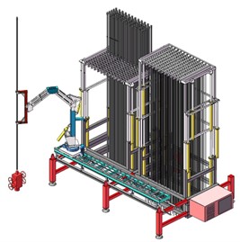
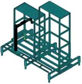
The finite element model of the tubing and sucker rod vertically handling equipment is also shown in Fig. 1. The model material is Q345 steel, which has an elastic modulus of 210 GPa, a Poisson’s ratio of 0.33, a yield limit of 345 MPa, and a density of 7850 kg/m3. The overall finite element model consists of 129513 elements and 226560 nodes. For the main frame made up of hollow square steel, we selected the 3D linear beam element BEAM188 for simulation with a total number of elements is 2218 and nodes number is 2166. The shell element SHELL181 is selected to be modeled as a plane in order to facilitate the subsequent load application, with 1496 elements and 1632 nodes. The SOLID186 element was used for 3D simulation modeling of the robot arm. The total element number of finite element model is 125617 and the total node number is 222918.
2.2. Wind load construction
Davenport wind velocity spectrum was adopted in this study [8]:
where denotes the frequency, is the average wind velocity at 10 m height within 10 minutes, is the ground roughness coefficient, which varies range is 0.003-0.03, and .
In the finite element analysis of structural dynamics, a random wind field is used and the power spectrum is set to the same as Davenport spectrum. Assuming that the random wind field is a smooth Gaussian random process, the harmonic superposition method is used to construct the random wind field through a series of harmonic functions of random amplitude and frequency. The random wind velocity is written by [9]-[11]:
where and are uncorrelated random vectors, and are chosen according to a prescribed power law energy spectrum:
denotes wave vectors, and the number vector of wind velocity can be given by:
denotes the node numbers, and is the frequency given by:
where is the instability parameter, which varies between 0 and 1, and 0.5 is adopted in the present investigation.
Power spectrum is assumed to have the expression:
where the upper limit length scale of the inertial range, is a constant, is the power of the energy spectrum.
According to the above algorithm, random wind velocity can be constructed. The total time is 600 seconds, and the interval is 0.1 seconds. The ground surface roughness is 0.005, the number of nodes is 6000. The frequency range is from 0.001 Hz to 6 Hz.
In addition, according to “GB/T 25428-2015 Drilling and workover derrick and base of drilling and production equipment for the oil and gas industry”, the relationship between wind velocity and wind pressure is as follows [12]:
where is the wind pressure, is the wind velocity, is the wind pressure height change coefficient, take , is the shape coefficient, for tower derrick and light derrick 1.25. When the vertical piping equipment considers the wind load and the vertical root is full, the wind velocity it can carry should not be less than 36 m/s.
Then the structural dynamic equations of the structure can be written as:
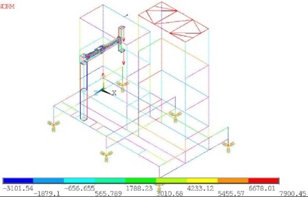
where , and denote mass matrix, damping matrix and stiffness matrix respectively, , and denote acceleration vector, velocity vector and displacement vector respectively, and is the external force vector. The load on the finite element model is illustrated in Fig. 2. The finite element equations of Eq. (8) can be solved with proper boundary conditions and initial conditions.
Fig. 2Illustration of load on the finite element model
3. Static numerical results
In order to evaluate the safety of the structure under extreme wind conditions, finite element analysis was performed using the model described in section 2.1 under extreme wind conditions with a static wind velocity of 36 m/s. The strength analysis of the structure was carried out by finite element method. The numerical results of equivalent stress are given in Fig. 3.
Fig. 3Equivalent stress contour
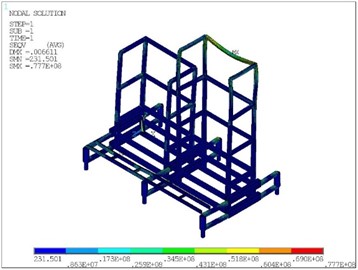
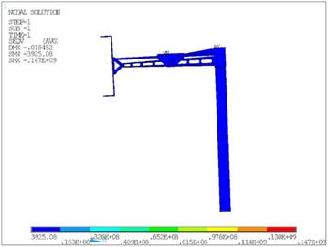
When the equipment is fully loaded and the wind velocity is 36 m/s, the maximum equivalent stress of the frame is 77.7 MPa, and the global maximum equivalent stress appears at the last connection of the robot arm is 147 MPa. It is far less than the yield limit of the material, and the structure is safe.
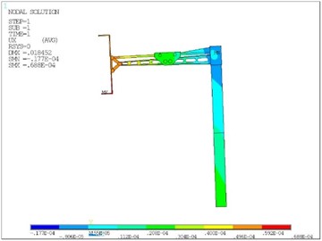
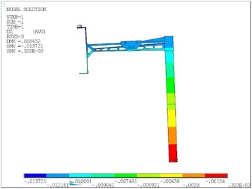
As can be seen from Fig. 4, due to the structural stiffness, the maximum total displacement of the structure is about 18 mm, which occurs at the grasping end of the robot arm. The total displacement can be divided into horizontal displacement in plane (, ) and vertical displacement in -direction. The horizontal displacement has a great influence on the positioning accuracy of the manipulator, which is related to the reliability of the automatic operation process. As can be seen from Fig. 5, the displacement in the -axis direction is about 0.0688 mm, and the maximum displacement in the -axis direction is 13.7 mm. Therefore, the displacement in the -axis direction has a greater impact on the positioning accuracy.
Fig. 4Total displacement contour
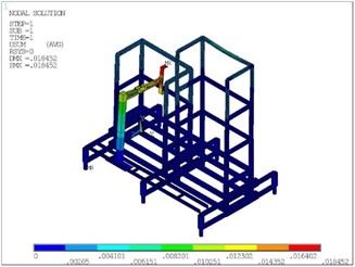
Fig. 5Horizontal displacement contour of the robot arm
a)-axis displacement component
b)-axis displacement component
4. Dynamic numerical result
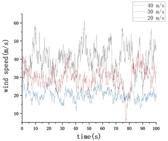
In order to further study the influence of dynamic wind load on the positioning accuracy of the manipulator, the displacement dynamic response of the grasping end of the manipulator in the horizontal plane under the action of random wind velocity (20 m/s, 30 m/s, 40 m/s, respectively) was investigated. Fig. 6 shows displacement response time-history of the typical position in two orthogonal directions on the horizontal plane.
By comparing the numerical results under different wind velocities, it can be seen that the increase of wind velocity has basically no effect on the displacement response of the typical position in the axis direction. The maximum displacement occurs in the initial transient stage of load excitation, with a maximal value of about 28 mm, and finally stabilizes at about 15 mm. The steady-state results are similar to the static results given in section 2.3. In the -axis direction, under the action of 40 m/s random wind field, the maximum displacement of the front end of the manipulator in the -axis direction is 0.8 mm. With the increment of wind velocity, the displacement of typical position in this direction increases, and the vibration effect becomes more obvious.
Fig. 6The displacement time-history response of the typical position
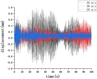
a)-axis displacement component
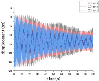
b)-axis displacement component
5. Conclusions
In this paper, the finite element model of the tubing and sucker rod vertically handling equipment is established. Davenport wind velocity spectrum is introduced to simulate the random time domain of natural wind. The stress and deformation of the pipe frame and the displacement of the grasping end of the robot arm under the action of dead weight load and static wind load are analyzed by finite element simulation. In the case of 36 m/s, the maximum vertical displacement is 18 mm, which appears at the grasping end of the robot arm. The global maximum equivalent stress is 147 MPa, which is far less than the material yield limit of 345 MPa. Then, the effect of fluctuating wind on the positioning accuracy of the manipulator is given, and it is found that when the structure enters the steady-state response stage, the results are similar to those in the static state. To sum up, under the meteorological environment investigated here, the strength and wind resistance performance of the project equipment is sufficient.
References
-
Q. Lei et al., “Technical status and development direction of workover operation of Petro China,” (in Chinese), Petroleum Exploration and Development, Vol. 47, No. 1, pp. 161–170, Feb. 2020, https://doi.org/10.1016/s1876-3804(20)60015-5
-
Q. Lei and Y. L. Li, Downhole Operation. Beijing, P. R. China: Petroleum Industry Press, 2019.
-
Q. Wu et al., Downhole Operation Supervision. Beijing, P. R. China: Petroleum Industry Press, 2014.
-
X. Zheng et al., “Progress and prospects of oil and gas production engineering technology in China,” (in Chinese), Petroleum Exploration and Development, Vol. 49, No. 3, pp. 644–659, Jun. 2022, https://doi.org/10.1016/s1876-3804(22)60054-5
-
C. S. Dai and E. D. Guan, “Study on mechanical drag and spread tech for tubing in work over operation of oilfield,” (in Chinese), Well Testing, Vol. 16, pp. 19–21, 2007.
-
H. H. Song, “Research and application of mechanized tubing delivering and handling equipment,” (in Chinese), Drilling and Production Technology, Vol. 39, No. 3, pp. 83–86, 2016.
-
“CN106401505B An automatic conveying Equipment and conveying method for Tubing and sucker rod in workover operations,” 2016.
-
A. G. Davenport, “The spectrum of horizontal gustiness near the ground in high winds,” Quarterly Journal of the Royal Meteorological Society, Vol. 87, pp. 194–211, 1961.
-
P. Flohr and J. C. Vassilicos, “A scalar subgrid model with flow structure for large-eddy simulations of scalar variances,” Journal of Fluid Mechanics, Vol. 407, pp. 315–349, Mar. 2000, https://doi.org/10.1017/s0022112099007533
-
F. Nicolleau and G. Yu, “Two-particle diffusion and locality assumption,” Physics of Fluids, Vol. 16, No. 7, pp. 2309–2321, Jul. 2004, https://doi.org/10.1063/1.1736673
-
R. H. Kraichnan, “Diffusion by a random velocity field,” The Physics of Fluids, Vol. 13, No. 1, pp. 22–31, Jan. 1970, https://doi.org/10.1063/1.1692799
-
“Petroleum and Natural gas industries-Drilling and Production Equipment-Drilling and Well-servicing Structures,” Standard ID: GB/T 25428-2015, 2015.
About this article

The authors have not disclosed any funding.
The datasets generated during and/or analyzed during the current study are available from the corresponding author on reasonable request.
The authors declare that they have no conflict of interest.
