Abstract
It is a known fact that the world's dependence on electrical energy is increasing day by day. The fact that electrical energy has some advantages over other types of energy, the increasing world population and changing living conditions can be considered among the reasons for this increase. This increase in dependence on electrical energy can be met by expanding existing facilities and establishing new facilities. In these studies, the transmission of electrical energy from the place where it is produced to the place where it is consumed poses important problems as the system expands. Some work is required to eliminate these technical and economic problems and to ensure stable operation of the system. These are problems that were not considered beforehand as the system grew. One of these problems is the ferroresonance phenomenon that occurs at the fundamental frequency due to the nonlinear magnetization characteristics of transformers. Ferroresonance is a resonance phenomenon that occurs in an electrical circuit containing an iron-core self-coil as a nonlinear element. This resonance manifests itself with sudden oscillations in the output size of the system caused by a small change in the amplitude or frequency of a magnitude applied to the input of the system. High voltage transmission lines are double-circuit lines that share the same pole. In special cases such as maintenance or malfunction of such a transmission system, one of the lines can be disconnected from the system and continue energy transmission with the other line. In the high voltage transmission line, the system may oscillate due to the stored energy in the magnetic field of the transformer inductance on the disabled line and the electric field of the line capacity. This oscillation disappears after a certain period of time due to iron losses and other circuit losses. When these losses are covered by the other transmission line, permanent oscillations and over voltages may occur at the transformer terminals. All these events are the negative effects of ferroresonance on transmission systems. In the energy transmission system, ferroresonance phenomenon occurs. Over voltages may occur in case of idle power transformers in star point/isolated networks. In medium voltage networks, ferroresonance occurs due to the melting of a fuse, the opening and closing of voltage transformers with one pole, and the dissymmetry that occurs as a result of a connection process. These negative effects caused by ferroresonance in the energy transmission power system are discussed in detail within the subject of this study.
1. Introduction
Ferroresonance phenomenon; It is also defined as an event that occurs suddenly at high voltage and causes high-level harmonic distortions. The term ferroresonance refers to all oscillation phenomena that occur in an electrical circuit. Non-linear inductance in the circuit is effective in creating capacitance, a voltage source and low losses. Power networks consist of a large number of saturable inductors (power transformers, voltage measurement inductive transformers, shunt reactors) as well as capacitors. The main feature of this phenomenon is that it gives more than one stable steady-state response for the same type of network parameters. Ferroresonance can be triggered in transient situations (high voltages caused by lightning strikes, energizing, and cutting of transformers or loads, occurrence or clearing of errors) or during operation. In this case, higher than a normal steady state (at the same sinusoidal frequency as the source) it can jump to a steady state caused by ferroresonance, which can be characterized by a high level of voltage and harmonics and can cause serious damage to the materials.
The changing capacity of the transformer circuit breaker when opening and closing the circuit may cause zero voltage at the transformer ends, or a permanent damaging voltage above the normal voltage. In order to avoid situations such as premature failure of protection devices, damage to devices such as power transformers or voltage transformers, and production losses, it is important to analyze the cause of ferroresonance and predict the regions where it may occur. Little is known about ferroresonance. The reason for this is that it is very rare in power systems and voltage transformers and cannot be analyzed and predicted with calculation methods based on linear approach. This lack of information leads to the idea that ferroresonance is responsible for many unexplained high voltage faults and damages. Ferroresonance is difficult to analyze because it does not show regularity and it is not possible to predict ferroresonance events that will occur. It may be affected more by the initial circuit parameters than by a stable steady-state response. Transient voltage response may occur due to phase-neutral lines damaging the circuit, high voltages induced as a result of lightning striking the lines on energized or de-energized equipment, or sudden small changes. Ferroresonance is the normal steady-state response of the system with sudden changes due to nonlinear jumps. It creates severe harmonic distortions and high voltages up to steady state, causing harmful effects on power system equipment.
It is thought that the increasing voltage levels in transmission and distribution systems in the planned future will create a different relationship between the line capacitance and the magnetic saturation curves of transformers than today. This change is in the positive direction of the ferroresonance phenomenon.
1.1. Examination of ferroresonance phenomenon in energy transmission power system by graphical method
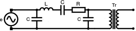
In order to examine the ferroresonance phenomenon in the high voltage energy transmission system, considering the equivalent circuit in Fig. 1 of one phase of a long energy transmission line with an idle-operating power transformer at the end, the system can be reduced to a series or parallel ferroresonance circuit, even if it is more complex.
Fig. 1Equivalent circuit of a long energy transmission line, composed of series and shunt, with an idle transformer at the end
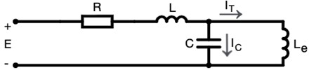
In this case, the reduced equivalent circuit of the energy transmission line in terms of relative elements and unit frequency can be used in graphical analysis. We can draw this circuit as in Fig. 2.
Fig. 2Reduced equivalent circuit of the energy transmission line in terms of relative elements and unit frequency
The magnetization characteristic of the transformer can usually be obtained experimentally. Let the curve a shown in Fig. 3 be the voltage-current characteristic of a transformer at the fundamental frequency extracted for inductive and capacitance currents. Since the voltage at the ends of the capacitor is proportional to the current () passing through it, the line with slope / can be drawn as the voltage-current characteristic of the capacitor, taking into account the phase status of the transformer with respect to the current . The current passing through the resistance and self-inductance passing through the capacitor it is the phasor sum of current and current passing through the transformer.
Fig. 3Characteristics of a transformer and a linear capacitor
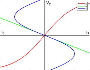
If these total characteristics are shown point by point, the curve shown as curve c in Fig. 3 is obtained. In this case, the circuit given in Fig. 2 can be reduced to a circuit consisting of a linear resistance connected in series, a linear self-inductance and a nonlinear element with a voltage-current characteristic like curve. The reduced circuit can be plotted in this case as shown in Fig. 4.
Fig. 4Reduced state of the circuit in Fig. 2
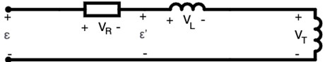
Since the amplitude of the voltage at its ends will be proportional to the amplitude of the current passing through it, the amplitude of this voltage drop can be shown, along with other characteristics, with the line , whose slope is WL. This characteristic nonlinear element is shown with dashed lines in Fig. 5. For the circuit in Fig. 4, Eq. (1) can be written:
For any value of applied voltage, the voltage drop characteristic in self-inductance generally cuts off at three points. Considering Eq. (1), the phasor diagrams of the voltages at the cut-off points are shown in Fig. 5.
The current I passing through the self inductance is ninety degrees ahead of the phase in the second and fourth quadrants compared to the voltage at the ends of the nonlinear element (transformer end voltage). If the operating points are in the first and third quadrants, it will be ninety degrees out of phase.
The operating points indicated by 1 and 2 are stable, and the operating points indicated by 3 are unstable. The point at which the operation will be depends on the phase angle of the applied voltage at the moment it is applied. at points 1 and 2, at point 3, opposite emf it affects as.
If the amplitude of the voltage shown with in Fig. 4 and Fig. 5 increases or decreases in any way, the line d, which shows the voltage drop in self-inductance, will shift upwards or downwards, remaining parallel to the direction of Eq. (1). At a certain value of voltage , the line , which shows the amplitude of the voltage drop in the self-inductance, may be tangent to the curve, which is characteristic of the nonlinear element, at a point or . While in this operating state, a small increase in the amplitude of will cause a jump from point to point . The voltage at the ends of the nonlinear element, in other words the transformer winding terminal voltage, will jump from to a higher value, with its phase rotating 180° electrical degrees relative to its initial position. The current passing through the resistor and self-inductance will jump from the IL1 value to a smaller value, and the phase will return to its initial position by 180° electrical degrees. If the operating point was in the fourth quadrant, there would be a jump from point to point .
The critical value of the applied voltage that will cause a jump. EKR can be easily found with the graphical construction shown in Fig. 6.
Fig. 5Characteristics of a linear self-inductance and nonlinear element and phasor diagrams of voltages at the operating point
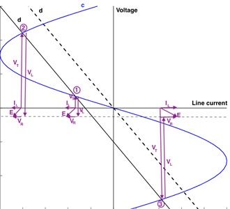
Fig. 6Jump-output and jump-destination points of the voltage at the transformer ends
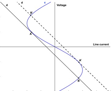
If the self-inductance value was taken as variable, the slope of the voltage drop line of this element would change and the above-described event could occur again. It is clearly seen in Fig. 6 that points and are jump-exit points, and points and are jump destinations. We can draw the following conclusion from this graphic analysis. If the slope of the line d, which shows the voltage drop in self-inductance, is greater than the slope of the initial tangent of the curve , which shows the voltage at the ends of the nonlinear element, jump resonance, which is a special case of ferroresonance, may occur at a certain value of the applied voltage.
1.2. Ferroresonance in transformers in energy transmission and power system
The ferroresonance problem of unloaded transformers connected to transmission systems is examined in the plane. Critical curves in the parameter plane for different nonlinear elements are obtained from the first order generalized equations of . These obtained values resonate for only one critical value of and . When two critical values of and are available, the mathematical model is established. and are between two critical values. If it is present, ferroresonance does not occur.
1.2.1. Block diagram of the unloaded transformer connected to the transmission system
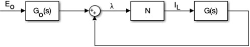
In Fig. 7, the connection of the open-circuit single-phase transformer to the transmission line is shown. The block diagram is shown in Fig. 8.
Fig. 7Diagram of the system in operating state
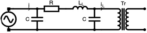
Fig. 8Block diagram of the system in operating state
The equation of this circuit is shown in Fig. 7. The equation of nodes 1 and 2 is expressed as follows:
The voltage for the second node is:
Circuit gain is:
When the capacity current passing through the node point is written and the node equations are written for the circuit gain:
To obtain the value in the block diagram, we obtain the equation by using the conversion ratio and writing the circuit impedance formulas:
In this case, the stable operation of the system is examined with the increasing identification function. Fig. 5 shows an increase in cases where there is an increasing deviation in steady-state operation for the system:
where is a current peak value, is a incremental deviation () and is a phase angle between deviation and grid signal. Nonis are incremental descriptive functions, and if the amplitude of is increased and remains within (–1, 0) in the Nyqust plot, it is unstable. In this case, after a while it reaches a point where there is no critical point. The increase in while passing through is multiplied by the factor and then multiplied by to obtain the stability criterion:
Here, while changes from zero to infinity, the system will be stable as long as drawing point – remains inside the drawing.
1.3. Various nonlinear cases - envelope equation
While the magnetization characteristic is our symmetry, depending on the degree of saturation:
For practical purposes the degree of saturation of power transformers can be conveniently represented by 5th order nonlinear. We should also point out that Eq. (7) was obtained by fitting the curve to the real magnetization curve.
1.3.1. Ferroresonance state
Increasing the amplitude of the envelope curve as depending on causes the function to increase:
The plot starts from the origin with a phase shift of 90° for 0 and is on the negative real axis for with a phase shift of 180°. Therefore, the larger n is, the more sensitive the ferroresonance phenomenon in the system.
2. Conclusions
One of the problems that arise with the expansion of the interconnected energy system is ensuring system stability. One of the events that negatively affects stability is the ferroresonance phenomenon. These effects must be eliminated in order to ensure stable operation. Ferroresonance is a resonance phenomenon that occurs in an electrical circuit containing an iron-core self-coil as a nonlinear element. In a series or parallel RLC circuit, at a certain value of the applied voltage, regardless of frequency, the inductive reactance of the coil is equal to the capacitive reactance of the capacitor. The circuit operates unstable unless certain conditions are met. The output magnitudes are exponential and limited by magnetic saturation. The sinusoidal shape of the output voltage is distorted by ferroresonance. Additionally, a phase shift occurs between the input and output voltages. Graphical and analytical methods are used to examine the ferroresonance phenomenon theoretically. The graphical method is suitable for systems containing multiple nonlinear elements. However, some conditions will be required for it to be applied to the system. For example. The current-voltage characteristics of nonlinear elements must be either pure inductive or pure capacitive. Analytical solutions are sought for systems with only one nonlinear element. For example, to eliminate ferroresonance occurring in transformers as nonlinear elements:
a) According to the LC parameter plane, without adding any resistance:
b) In the RC parameter plane:
Condition must be met:
c) In the LR parameter plane:
where value was determined as the critical value for ferroresonance.
We can summarize the practical solutions for the main ferroresonance problems seen in the energy transmission system as follows.
1) In order to prevent ferroresonance that occurs as a result of shifting of the neutral point in a network with a neutral conductor, a resistance of appropriate value is connected between the neutral and the ground.
2) Ferroresonance occurring during the opening of a phase in power transformers is an active load of around 5-10 % of the secondary rated power can be resolved by connecting.
3) Preventing ferroresonance, which occurs when the 3-three phases are switched on and off, depends on certain conditions being met. The different extinction times of the arcs occurring during switching on and off create different initial conditions in the phases. This difference in initial conditions causes ferroresonance. Therefore, to prevent this type of ferroresonance, the phases must be opened and closed simultaneously.
4) If the natural frequency of a transformer feeding a low voltage network with a large inductive reactance is greater than the system frequency, the sinusoidal form of the network voltage is distorted. Ferroresonance occurs when the natural frequency of the secondary circuit is equal to one of the harmonics of the transformer voltage. This situation is eliminated by loading the secondary circuit with active load.
References
-
I. Temiz, “Ferroresonance phenomenon in power systems,” (in Turkish), Master’s Thesis, Marmara University, Institute of Pure and Applied Sciences, Istanbul, Türkiye, 1988.
-
F. Akça, “Analysis of ferroresonance phenomenon in energy transmission systems,” (in Turkish), Master’s Thesis, Sakarya University, Institute of Pure and Applied Sciences, Sakarya, Türkiye, 2002.
-
Cadick Corporation, “Ferroresonance,” TECHNICAL BULLETIN-004a, 2002.
-
P. Ferracci, “Ferroresonance,” Cahier Technique 190 Groupe, Schneider Technique Publication, 2002.
-
Y. Alparslan, “Voltages resulting from magnetic saturation in the iron core in electrical systems (Ferroresonance),” in Electrical Engineering Technical Congress, Vol. 19, pp. 147–153, 1975.
-
T. Ç. Akıncı, “Determination of ferroresonance phenomenon in power systems using spectral and wavelet analysis methods,” (in Turkish), Doctoral Thesis, Marmara University, Institute of Pure and Applied Sciences, Istanbul, Türkiye, 2009.
-
G. Engdahl, Ferroresonance in Power Systems. Energiforsk, 2017.
-
T. C. Akinci, O. Akgun, M. Yilmaz, and A. A. Martinez-Morales, “High order spectral analysis of ferroresonance phenomena in electric power systems,” IEEE Access, Vol. 11, pp. 61289–61297, 2023, https://doi.org/10.1109/access.2023.3286817
Cited by
About this article

The authors have not disclosed any funding.
The datasets generated during and/or analyzed during the current study are available from the corresponding author on reasonable request.
Each author contributed equally.
The authors declare that they have no conflict of interest.
