Abstract
Presently, there is significant emphasis on researching the automation of processes, systems, and devices across scientific and technical fields. This emphasis extends notably to sectors like aerospace, robotics, and electric transportation technology. One effective approach to tackling the technical and design challenges of automating various technological tools and processes is through the implementation of adaptive systems. Specifically, achieving efficient and reliable power transmission in electric autonomous and mobile vehicles can be realized by employing an adaptive mechanical drive with two degrees of freedom. The adaptability of this two-mobile system is enabled by introducing an innovative continuous multi-speed drive design featuring an additional friction coupling. The primary attribute ensuring the reliability of this self-adjusting mechanical drive lies in its ability to autonomously adapt to external loads. This is made possible by a balancing friction coupling that establishes a connection between the frictional torque and the relative angular velocity.
Highlights
- There is a significant emphasis on researching automation across scientific and technical fields, particularly in sectors like aerospace, robotics, and electric transportation technology.
- One effective approach to addressing the technical and design challenges of automation is through the implementation of adaptive systems.
- adaptive mechanical drive with two degrees of freedom, featuring a continuous multi-speed drive design with an additional friction coupling to enable adaptability and reliability.
1. Introduction
The advancement of modern automated control systems for drives heavily relies on improving designs of multi-stage continuously variable transmissions (CVTs). As mechatronics technology evolves, various innovative drive mechanisms are being integrated into drive systems to enhance transmission efficiency [1]. One prominent trend is the effort to reduce the number of stages while maintaining a broad control range. In the pursuit of enhancing the efficiency of drive systems for mobile robots and electric vehicles, extensive research is focused on incorporating multi-speed transmissions [2].
Multi-speed gearboxes have garnered significant attention as potential components for transmissions in battery electric vehicles. This exploration is driven by the advantage of incorporating multiple gear ratios, which keeps the electric motor operating within a more efficient range, resulting in reduced energy consumption for the vehicle and improved dynamic performance [3]. However, integrating a multi-stage gearbox in an electric vehicle increases production costs and requires the implementation of gearbox control mechanisms [4] and the development of a gear shift algorithm [5].
Research studies have shown that multi-speed transmissions can lower a vehicle’s total energy consumption by 2 % to 20 % across different driving cycles [5-7], and increase drive wheel torque by up to 35 % [8]. However, this comes at the expense of reduced overall efficiency. For heavy-duty vehicles, which require substantial torque for acceleration due to their significant mass, the inclusion of multi-speed gearboxes is particularly crucial, enabling the utilization of a machine with lower torque and reduced tractive effort [9].
2. Description of the kinematic chain of the adaptive drive
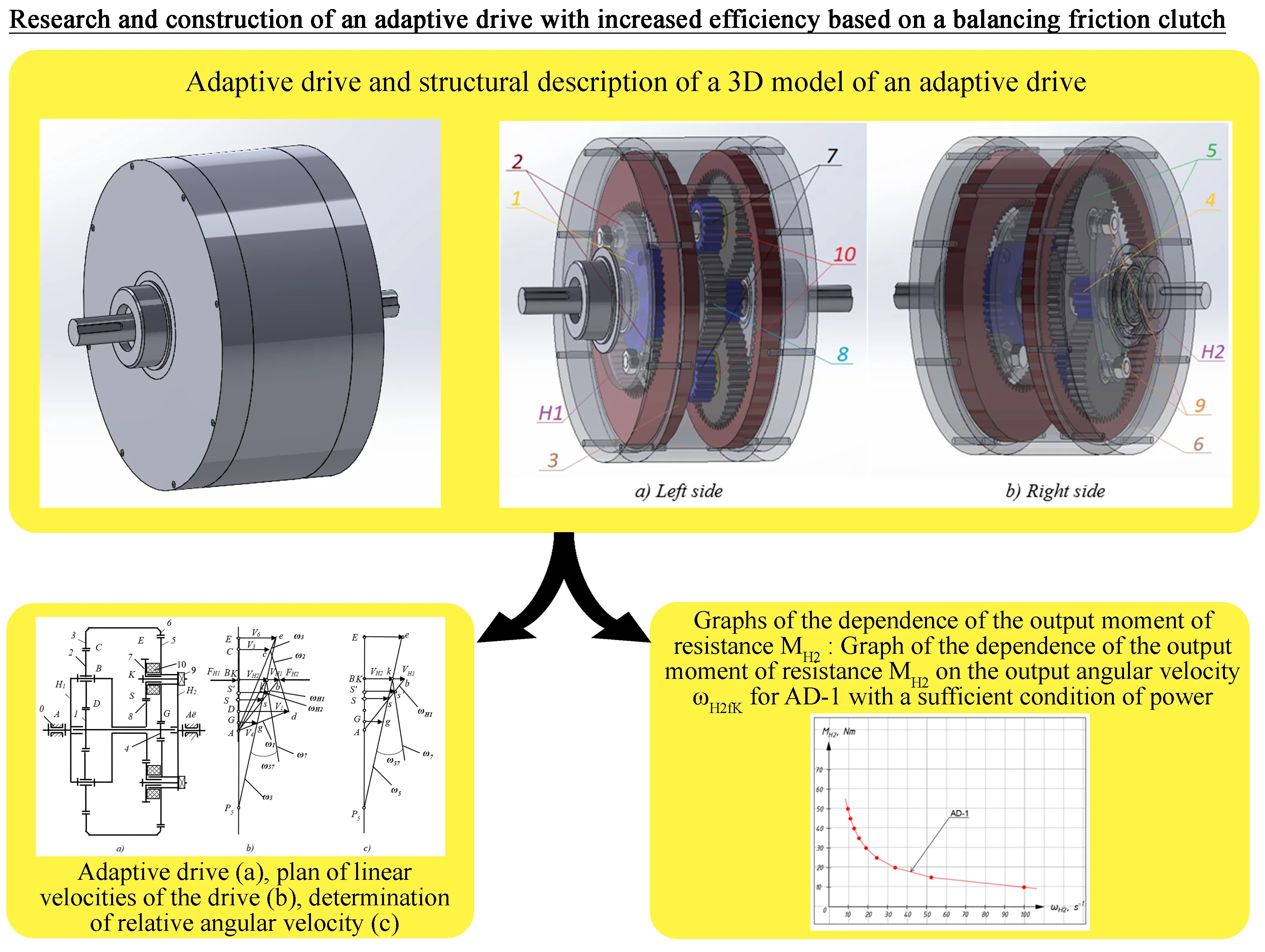
An adaptive drive, denoted as AD, functions as a self-adjusting mechanism, as depicted in Fig. 1. This drive achieves power adaptation by ensuring that the speed of the output link changes in proportion to variations in the output load. Remarkably, it possesses two degrees of freedom despite being driven by only one input, a characteristic that appears to defy the conventional requirements for such a mechanism and the clarity of its motion. The underlying assumption is that the clarity of motion establishes the necessary and sufficient conditions for power adaptation, as expounded in reference [15]. A necessary condition is satisfied through the presence of a mobile closed loop comprised of gears, while the sufficient condition is achieved by introducing an additional constraint that correlates force and velocity.
Fig. 1Adaptive drive
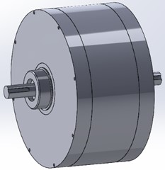
The kinematic chain of the adaptive gear variation, as shown in Fig. 2(a), comprises several essential components:
1) Initial Rack (Rack 0): This component marks the starting point of the chain.
2) Input Carrier ([carrier symbol]): This crucial element facilitates the transmission of input motion.
3) Closed Gear Loop 1-2-3-6-5-4: These interconnected gear wheels (1, 2, 3, 6, 5, 4) form a dynamic closed loop, playing a central role in the transmission mechanism.
4) Output Carrier ([carrier symbol]): Responsible for conveying the output motion.
5) Gears 8 and 7: These gears (8 and 7) create an additional parallel transmission path from the carrier [carrier symbol] to the satellite 5.
Within this closed loop, the following components are present:
1) Input Satellite 2: Integral to the closed loop, contributing to its dynamic operation.
2) Block of Sun Wheels 1-4: This set of sun wheels (1 and 4) collectively form a functional block within the closed loop.
3) Block of Ring Wheels 3-6: Similarly, the ring wheels (3 and 6) together constitute another block within the closed loop.
4) Output Satellite 5: This component represents the output element within the closed loop and plays a crucial role in the transmission process.
The operation of the drive unfolds as follows: the input shaft, linked to the input carrier [carrier symbol], initiates the transmission of motion to the input satellite 2. From there, the motion is conveyed to gear blocks 1-4 and 3-6, which then transfer it to both the output satellite 5 and the output carrier [carrier symbol]. Meanwhile, a separate kinematic chain, featuring an additional parallel transmission facilitated by gears 8 and 7, transmits motion from the input carrier [carrier symbol] to both the output satellite 5 and the carrier [carrier symbol]. It’s crucial to note that gears 8-7 in parallel are configured with a gear ratio matching that of the planetary kinematic chain, ensuring synchronized motion transmission and preserving the desired gear ratios and dynamics throughout the system.
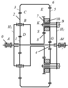
Fig. 2a) Adaptive drive, b) plan of linear velocities of the drive, c) determination of relative angular velocity
a)
b)
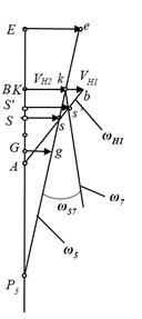
c)
Fig. 3Structural description of a 3D model of an adaptive drive
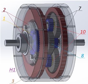
a) Left side
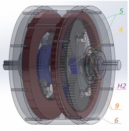
b) Right side
The parallel gear assembly 8-7 holds the potential to establish a robust force-velocity constraint. In this research, the implementation of such a constraint is realized by utilizing an adjustable friction coupling 10, which connects wheels 5 and 7 through an adjustable tension screw 9. This tensioning screw 9 is responsible for generating a normal reaction and the required frictional moment within the coupling 10 to achieve equilibrium.
For clarity, Fig. 2(c) presents a simplified plan showing linear velocities, aiding in visual comprehension, while Fig. 3 provides a structural depiction of a 3D model illustrating the configuration of the adaptive drive system.
3. Numerical calculation of the mathematical model of the adaptive drive
Numerical calculation of the mathematical model of the drive makes it possible to simply and quickly check the theoretical assumptions put forward. Let’s analyze the drive operation by numerical analysis of the developed mathematical AD-1 model corresponding to the necessary and sufficient condition of power adaptation [15].
The adaptive drive has the given constant motor power parameters on the input link and the given value of variable output torque resistance on the output link (Fig. 2(a)).
It is required to determine the power and kinematic parameters of the drive.
3.1. Model No. 1
Given: = 100 s-1, = 10 Nm, = [10, 15, 20, 25, 30, 35, 40, 45, 50] Nm, = 4 Nm, = 40; = 16; = 72; = 16; = 40; = 96.
Determine: , , , and .
Solution: Using Eq. (2), calculate the output angular velocity .
The obtained data are summarized in Table 1.
Table 1Values of output drag torque and output angular velocity for AD-1 with necessary condition of power adaptation
, Nm | 10 | 15 | 20 | 25 | 30 | 35 | 40 | 45 | 50 |
, s-1 | 100,0 | 66,7 | 50,0 | 40,0 | 33,3 | 28,6 | 25,0 | 22,2 | 20,0 |
Table 1 values correspond to the necessary condition of power adaptation. To determine a sufficient condition of power adaptation, it is necessary to solve the following task.
Next, we define the values , , , and . As an example, let's calculate the required parameters for = 10 Nm and corresponding = 100 s-1. The power balance of the kinematic chain with friction joint :
where .
Here where =.
Let’s determine the value of the frictional power using the following equation:
Let’s determine the value of the output angular velocity using the following equation:
Let’s determine the value of the efficiency of the mechanism according to the following equation:
According to this solution algorithm, we determine the remaining parameters that determine the sufficient condition of power adaptation at the corresponding values of and from Table 1. The obtained data are summarized in Table 2.
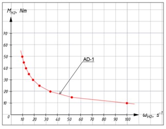
Based on the data in Table 2, plot the traction characteristic for AD-1 (without additional frictional constraint) as a dependence of the output resistance moment on the output shaft speed (Fig. 4(a)).
Fig. 4 shows comparative graphs of the characteristics of AD-1.
Table 2Results of calculations for AD-1 with a sufficient condition of power adaptation
, Nm | , s-1 | , s-1 | , s-1 | , W | , % | Average , % | |
10 | 100,0 | 100 | 0 | 0 | 100 | 100 | 63,4 |
15 | 66,7 | 13,4 | –53,3 | 213,2 | 52,5 | 78,7 | |
20 | 50,0 | –29,9 | –79,9 | 319,6 | 34,0 | 68,0 | |
25 | 40,0 | –56,0 | –96 | 384,0 | 24,6 | 61,6 | |
30 | 33,3 | –73,5 | –106,8 | 427,2 | 19,1 | 57,3 | |
35 | 28,6 | –85,6 | –114,2 | 457,0 | 15,5 | 54,3 | |
40 | 25,0 | –95,0 | –120 | 480,0 | 13,0 | 52,0 | |
45 | 22,2 | –102,4 | –124,6 | 498,4 | 11,1 | 50,2 | |
50 | 20,0 | –107,9 | –127,9 | 511,6 | 9,8 | 48,8 |
Fig. 4Graphs of the dependence of the output moment of resistance: Graph of the dependence of the output moment of resistance on the output angular velocity for AD-1 with a sufficient condition of power adaptation
4. Analysis of the results
Analysis of the obtained results allows us to draw the following conclusions:
1) There is a certainty of the obtained theoretical patterns of the interaction of the parameters of the mechanism. Fig. 4(b) confirms the reliable operation of the developed drive and the presence of the effect of power adaptation.
2) The developed mechanism has a power adaptation of a similar order, high reliability of operation (definability of movement).
3) Model AD-2 has a reliable range of output angular velocity.
4) The efficiency of the AD-2 model is 92 % on average, which is much higher than the efficiency of the AD-1 model, which averages 63 %.
5) Summarizing points 3 and 4 of the analysis, it can be seen that, compared with the AD-1 model, there was a slight decrease in the control range of the AD-2 model, but at the same time, the efficiency increased significantly.
5. Conclusions
A slight increase in power losses due to the addition of a friction coupling slightly affects the efficiency and the control range, which remains within a fairly wide range. This is due to the good location of the friction coupling allowing a low relative velocity of the interacting links. Friction coupling creates an efficient force-velocity constraint.
The friction coupling effectively establishes a force-velocity constraint, which serves to replace the unbalanced reaction and guarantees the determinability of motion across a broad range of regulation settings.
References
-
D.-H. Kim and S. B. Choi, “Composite control law for nonlinear systems with mismatched disturbances for a ball-ramp dual-clutch transmission,” IEEE Transactions on Intelligent Transportation Systems, Vol. 24, No. 10, pp. 11265–11277, Oct. 2023, https://doi.org/10.1109/tits.2023.3275287
-
M. R. Ahssan, M. M. Ektesabi, and S. A. Gorji, “Electric vehicle with multi-speed transmission: A review on performances and complexities,” SAE International Journal of Alternative Powertrains, Vol. 7, No. 2, pp. 169–181, Dec. 2018, https://doi.org/10.4271/08-07-02-0011
-
E. Louback, F. Machado, L. Bruck, P. J. Kollmeyer, and A. Emadi, “Real-time performance and driveability analysis of a clutchless multi-speed gearbox for battery electric vehicle applications,” in 2022 IEEE/AIAA Transportation Electrification Conference and Electric Aircraft Technologies Symposium (ITEC+EATS), pp. 1041–1046, Jun. 2022, https://doi.org/10.1109/itec53557.2022.9814032
-
H. Laitinen, A. Lajunen, and K. Tammi, “Improving electric vehicle energy efficiency with two-speed gearbox,” in 2017 IEEE Vehicle Power and Propulsion Conference (VPPC), Dec. 2017, https://doi.org/10.1109/vppc.2017.8330889
-
T. Hofman and C. H. Dai, “Energy efficiency analysis and comparison of transmission technologies for an electric vehicle,” in 2010 IEEE Vehicle Power and Propulsion Conference (VPPC), pp. 23–28, Sep. 2010, https://doi.org/10.1109/vppc.2010.5729082
-
A. Sorniotti, S. Subramanyan, A. Turner, C. Cavallino, F. Viotto, and S. Bertolotto, “Selection of the Optimal Gearbox Layout for an Electric Vehicle,” SAE International Journal of Engines, Vol. 4, No. 1, pp. 1267–1280, Apr. 2011, https://doi.org/10.4271/2011-01-0946
-
Q. Ren, D. A. Crolla, and A. Morris, “Effect of transmission design on electric vehicle (EV) performance,” in 2009 IEEE Vehicle Power and Propulsion Conference (VPPC), pp. 1260–1265, Sep. 2009, https://doi.org/10.1109/vppc.2009.5289707
-
B. Eberleh and T. Hartkopf, “A high speed induction machine with two-speed transmission as drive for electric vehicles,” in International Symposium on Power Electronics, Electrical Drives, Automation and Motion, 2006. SPEEDAM 2006., pp. 249–254, Aug. 2023, https://doi.org/10.1109/speedam.2006.1649779
-
F. Machado, P. Kollmeyer, D. Barroso, and A. Emadi, “Multi-speed gearboxes for battery electric vehicles: current status and future trends,” IEEE Open Journal of Vehicular Technology, Vol. 2, pp. 419–435, Jan. 2021, https://doi.org/10.1109/ojvt.2021.3124411
-
J. Ruan, P. D. Walker, J. Wu, N. Zhang, and B. Zhang, “Development of continuously variable transmission and multi-speed dual-clutch transmission for pure electric vehicle,” Advances in Mechanical Engineering, Vol. 10, No. 2, p. 168781401875822, Feb. 2018, https://doi.org/10.1177/1687814018758223
-
J. Hu, F. Xiao, H. Peng, and W. Zhao, “CVT discrete speed ratio optimizations based on energy efficiency for PHEV,” Alexandria Engineering Journal, Vol. 61, No. 5, pp. 4095–4105, May 2022, https://doi.org/10.1016/j.aej.2021.09.038
-
A. Baibolov et al., “Map of zoning of the territory of Kazakhstan by the average temperature of the heating period in order to select a heat pump system of heat supply: A case study,” Energy Sources, Part A: Recovery, Utilization, and Environmental Effects, Vol. 44, No. 3, pp. 7303–7315, Sep. 2022, https://doi.org/10.1080/15567036.2022.2108168
-
A. Tleubayev et al., “Establishment of the necessary material and technical base lays the groundwork for the use of innovation in the grain industry,” Research Square, Aug. 2022, https://doi.org/10.21203/rs.3.rs-1869428/v1
About this article

This research has been funded by the Science Committee of the Ministry of Science and Higher Education of the Republic of Kazakhstan (Grant No. AP14869840 “Research and development of ultra-broadband multi-antenna wireless transmission of information between interfaces”).
The datasets generated during and/or analyzed during the current study are available from the corresponding author on reasonable request.
The authors declare that they have no conflict of interest.
