Abstract
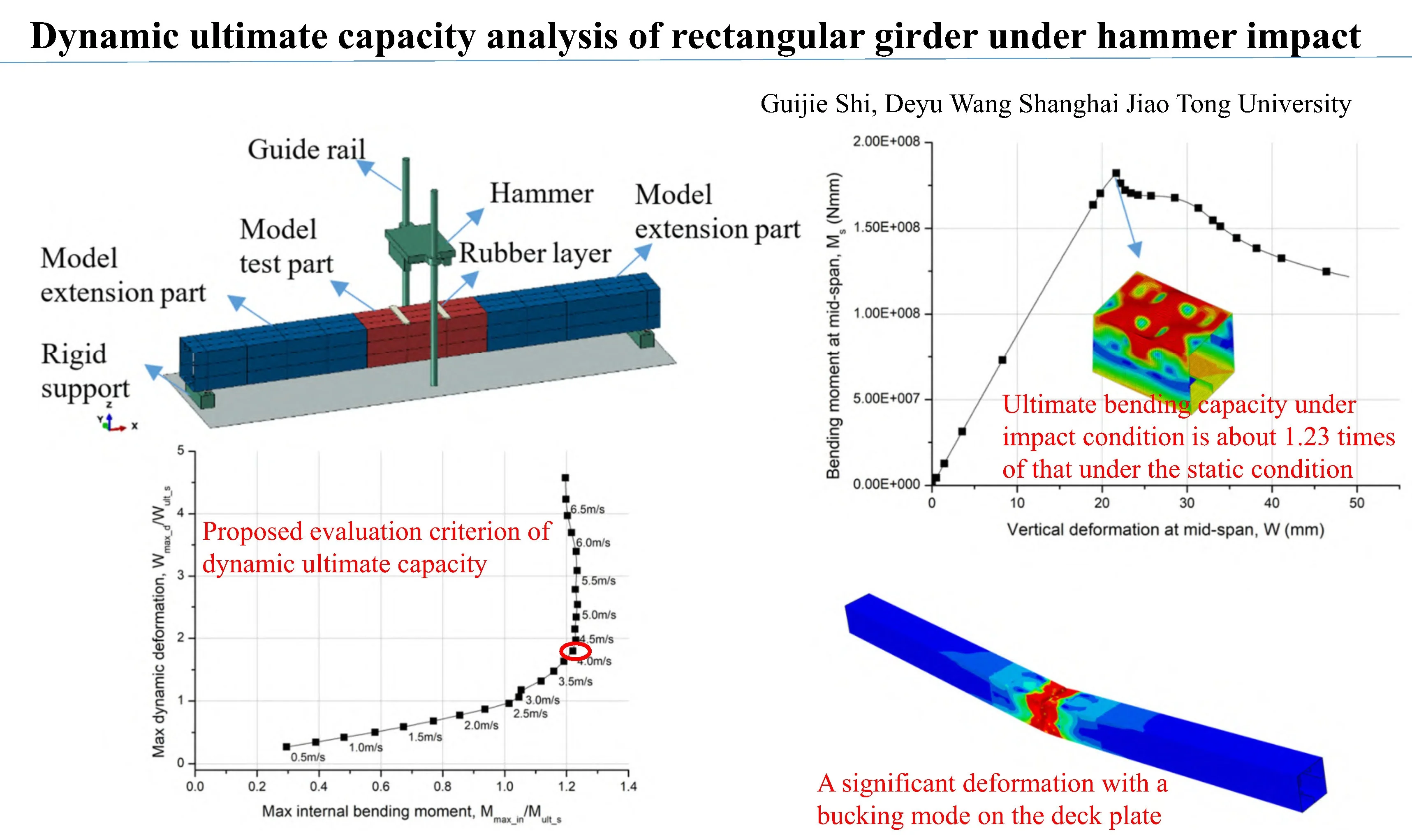
The dynamic failure and ultimate capacity analysis of rectangular girder under bending moment has not been fully studied. In this paper, a rectangular girder scaled from actual ship deck structure is selected as the study objective to analyze the dynamic failure and ultimate flexure capacity. The dynamic response under hammer drop impact is studied, and then two criteria of dynamic ultimate flexure capacity of the girder are proposed based on the bending moment in section and permanent deformation. The novelty of this paper is the proposed evaluation criterion of dynamic ultimate capacity.
Highlights
- An evaluation criterion of dynamic ultimate capacity has been proposed.
- Ultimate bending capacity under impact condition is proved to be about 1.23 times of that under the static condition.
- Significant deformations of several half-waves occurred on the middle deck plate under impact conditions.
1. Introduction
Recent catastrophic incidents show that dynamic load may be one of the causes for structure failure. The evaluation of structural dynamic strength has a large differences for current evaluation methods. Al-Rifaie et al. [1] found that the dynamic strength capacity could be higher than the static strength. Yang and Wang [2] proved that the amplitude of structural response under dynamic load could reach up to 1.6 times of that under static loads. Jagite et al. [3] found that the dynamic strength could be increased by more than 5.9 % compared that under the static loads for container ship.
When the load duration times was extremely short, the structures could not react immediately, as pointed out by Yamada [4]. Different from with static condition, the inertia terms should be considered in the dynamic response. Due to the inertia effect, the applied bending moment on the structure would be not the same as the internal bending moment. The three-point bending test under one hammer impact has be carried out by Duarte et al. [5] to study the bending behavior. A series of drop-weight tests for the double-hat structure under lateral impacts has been carried out by Sun et al. [6] to show their crashworthiness.
In this paper, a rectangular girder scaled from the actual ship deck structure is chosen as the objective of the analysis. The ultimate capacity and failure modes are discussed in static bending and hammer impact condition.
2. Study objective
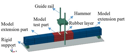
The rectangular girder has a cross section of 400 mm×400 mm with plating thickness of 3 mm and FB60×3 stiffener, as shown in Fig. 1. The span of stiffener is set as 600 mm. The whole length of the rectangular girder is 7000 mm. Four transverse bulkheads are set at the end support and the applied load position to withstand local force concentration, as shown in Fig. 2.
The elastic buckling strength of the plating and the stiffener web can be estimated [7]. The buckling strength of the plating is lower than that of the stiffener, as shown in Table 1. Therefore, the 1st buckling mode will present on the plating.
Fig. 1Cross section
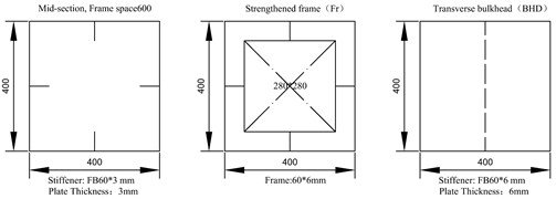
Fig. 2First buckling mode
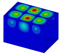
Table 1Buckling strength of the member for the rectangular girder
Plating length | , mm | 600 |
Plating width | , mm | 200 |
Stiffener web height | , mm | 60 |
Stiffener web thickness | , mm | 3 |
Plating buckling | , MPa | 175.5 |
Stiffener buckling | , MPa | 298.6 |
3. Ultimate capacity of the girder under static bending
The nonlinear finite element analysis can be used to evaluate the ultimate capacity of the ship structures [8]. The meshing size is set to 10 mm. In the longitudinal direction, the element aspect ratio is kept to be close to 1.0. The S4R reduced integration element with hourglass control is used.
Ship steel is used to design the rectangular girder with Modulus 2.06E+5 MPa, Poisson factor 0.3, and Yielding strength of 360 MPa. The steel is assumed to be a perfect elastic-plastic material. The coordination is located as the center point of the 1st transverse bulkhead.
Simply support conditions are assumed at the both ends. Two loads are applied as uniform nodal forces at the intersection of the transverse bulkhead and the deck plat. The middle section of the rectangular girder will be under pure bending. The first buckling mode, as shown in Fig. 2 is used to simulate the dangerous distribution of initial imperfection. The amplitude of initial imperfection is set as 1 mm.
On the basis of the load incremental method, the arc-length method is chosen to analyze the ultimate capacity of the rectangular girder. The initial applied force can set as a small value, such as 100 N. The bending moment at the mid-span can be calculated by the applied force and force arm .
The curve of the mid-span bending moment and vertical deformation (along -axis) for the rectangular girder is shown in Fig. 3. The maximum value of bending moment is defined as the ultimate capacity 1.82E+08 N·mm, and its corresponding deformation is 21.7 mm.
Fig. 3Moment and deformation
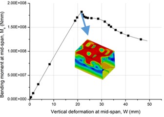
Fig. 4Drop hammer impact
4. Dynamic ultimate capacity of girder under drop hammer impact
Under the hammer impact in the middle, as shown in Fig. 4, two dynamic loads will be acted on the rectangular girder at the same time, and the girder will produce an instantaneous sagging deformation. Besides the applied load, the FE model in Section 3 also applied in the dynamic analysis.
The hammer has dimensions of length 1300 mm, width 450 mm and height 310 mm, which is made of aluminum 2024 with yield strength 350 MPa. In order to increase the load duration time of contact force, a layer of rubber should be tied on the impact position. The rubber has dimensions of length 100 mm, width 450 mm and thickness 20 mm. In the FE analysis, the hammer and the rubber layer are simulated by the linear solid element C3D8R.
Hyper-elastic constitutive model is used to describe the nonlinear stress-strain of rubber. Yeoh model is suitable for load cases with small and medium strains (30 %-40 %). The Cowper-Symonds constitutive model is usually used. The coefficients 3200 and 5 is used for higher tensile steel.
The hammer weight is kept unchanged. A series of various drop hammer velocity in vertical direction is applied on the rectangular girder to obtain the a critical load scenario inducing the structural failure.
The applied bending moment on the rectangular girder in the mid-span can be estimated by the applied force and the force arm . By the hammer impact, the impact force duration time is about 0.006 s. The force shape variation as time is close to the half-sine type. As the impact velocity increases, the applied force is increased linearly.
When the deformation reaches to the max value, the deformation distributions are shown in Fig. 5. The middle test part shows a significant deformation with a bucking mode on the deck plate. There are 3 half-wave concave-convex deformations on the deck plate of the middle test part. It is difficult to find a load case of producing a sudden change of deformation.
Fig. 5Deformation distribution
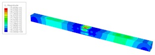
a) Hammer impact velocity 1.5 m/s
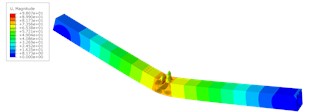
b) Hammer impact velocity 5.5 m/s
In the dynamic response analysis, it is important to distinguish the external applied bending moment () and the internal bending moment in the cross section (). The bending moment in the cross section will not be equal to the applied bending moment.
As the hammer impact velocity increases, the bending moment in the cross section will slightly increase. However, when the impact velocity reaches a certain level, the max value of the bending moment in the cross section does not increase anymore.
The max value of vertical deformation and max value of bending moment in the cross section at the mid-span for the girder are plotted in Fig. 6. At the smaller hammer impact velocity, that is 2.5 m/s, the curve of vertical deformation and bending moment in section shows a linear trend, and the rectangular girder is in elastic state. From 3.0 m/s to 4.0 m/s, the increase rate of the vertical deformation has been accelerated, but the internal moment has a smaller increase due to local buckling and yielding. When 4.25 m/s, the bending moment in section reaches its maximum and the vertical deformation has a great increase. The cure slope of vertical deformation and bending moment in section almost become the maximum. Therefore, 4.25 m/s can be taken as the dynamical limit state under hammer impact.
The max bending moment in section 2.24E+8 Nmm, which is about 1.23 times of that under the static condition The applied dynamical bending moment 5.70E+8 Nmm = 3.14 . All the results of ultimate flexure capacity for the girder under hammer impact are listed in Table 2.
The permanent deformation can also be a signal of carrying capacity. The curve of permanent deformation after impact and applied dynamical bending moment for the rectangular girder is shown in Fig. 7. When the applied force is small, the rectangular girder almost presents no permanent deformation. When the applied bending moment increases, the permanent deformation grows linearly. At the critical state, the permanent deformation is about 1.03 times larger than the deformed at the static limit state.
Fig. 6Max deformation and moment
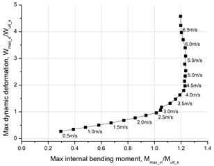
Fig. 7Permanent deformation and moment
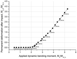
Table 2Ultimate flexure capacity of the rectangular girder under hammer impact
Hammer weight | , t | 0.62 |
Hammer falling velocity | , m/s | 4.25 |
Load duration time | , s | 0.006 |
Applied bending moment at dynamical limit state | , Nmm | 5.70E+8 |
Max bending moment in section | , Nmm | 2.24E+8 |
Max vertical deformation at dynamical limit state | , mm | 42.8 |
Max permanent deformation at dynamical limit state | , mm | 22.3 |
5. Conclusions
For dynamic strength analysis, the bending moment in cross section and permanent deformation can be used as the evaluation criteria for the critical states. The girder will reach its dynamical limit state when the maximum permanent deformation is about 1.0 times of deformation in static limit.
References
-
A. Al-Rifaie, Z. W. Guan, S. W. Jones, and Q. Wang, “Lateral impact response of end-plate beam-column connections,” Engineering Structures, Vol. 151, pp. 221–234, Nov. 2017, https://doi.org/10.1016/j.engstruct.2017.08.026
-
B. Yang and D.-Y. Wang, “Dynamic ultimate hull girder strength analysis on a container ship under impact bending moments,” International Journal of Offshore and Polar Engineering, Vol. 28, No. 1, pp. 105–111, Mar. 2018, https://doi.org/10.17736/ijope.2018.ty02
-
G. Jagite, F. Bigot, S. Malenica, Q. Derbanne, H. Le Sourne, and P. Cartraud, “Dynamic ultimate strength of a ultra-large container ship subjected to realistic loading scenarios,” Marine Structures, Vol. 84, p. 103197, Jul. 2022, https://doi.org/10.1016/j.marstruc.2022.103197
-
Y. Yamada, “Dynamic collapse mechanism of global hull girder of container ships subjected to hogging moment,” Journal of Offshore Mechanics and Arctic Engineering, Vol. 141, No. 5, pp. 1–15, Oct. 2019, https://doi.org/10.1115/1.4042267
-
I. Duarte, M. Vesenjak, and L. Krstulović-Opara, “Dynamic and quasi-static bending behaviour of thin-walled aluminium tubes filled with aluminium foam,” Composite Structures, Vol. 109, pp. 48–56, Mar. 2014, https://doi.org/10.1016/j.compstruct.2013.10.040
-
G. Sun, M. Deng, G. Zheng, and Q. Li, “Design for cost performance of crashworthy structures made of high strength steel,” Thin-Walled Structures, Vol. 138, pp. 458–472, May 2019, https://doi.org/10.1016/j.tws.2018.07.014
-
S. Gui-Jie and W. De-Yu, “Ultimate strength model experiment regarding a container ship’s hull structures,” Ships and Offshore Structures, Vol. 7, No. 2, pp. 165–184, Jun. 2012, https://doi.org/10.1080/17445302.2010.536391
-
M. C. Xu, D. Yanagihara, M. Fujikubo, and C. Guedes Soares, “Influence of boundary conditions on the collapse behaviour of stiffened panels under combined loads,” Marine Structures, Vol. 34, pp. 205–225, Dec. 2013, https://doi.org/10.1016/j.marstruc.2013.09.002
About this article

This project is supported by National Natural Science Foundation of China (Grant No. U2241266, 51809168 and 51979163), Marine Equipment Foresight Innovation Union Project (ZCJDQZ202304B02).
The datasets generated during and/or analyzed during the current study are available from the corresponding author on reasonable request.
The authors declare that they have no conflict of interest.
