Abstract
Using impedance modeling of transmitter antennas based on reactance parameters measured with a vector network analyzer, an equivalent of a short monopole antenna operating in the 1.5-30 MHz range was developed, suitable for operation of the transmitting device. Equivalent circuit diagrams of the considered tri-band antenna and their parameters for high-frequency ranges of 1.5-6, 6-18, and 18-30 MHz are presented. To verify the adequacy of the equivalent circuits to the parameters of the real antenna, frequency dependencies of the real and imaginary parts of the impedance of the monopole antenna equivalent are shown, along with the corresponding equivalent parameters for the given ranges. The analysis revealed a noticeable deviation of the modeling results in the 18-30 MHz range compared to the real antenna, indicating the need for further refinement of the input impedance model for monopole antennas over a wide frequency range to improve its accuracy. The developed models enable the use of modern wideband matching theory tools for antenna matching.
Highlights
- An analytical–numerical model of the input impedance of a short monopole in the high-frequency range is proposed.
- The effects of electrical length, ground plane, and matching circuits are taken into account.
- The model improves antenna matching efficiency.
- It enables optimization of antenna performance in modern wireless communication systems.
1. Introduction
Antennas used in mobile HF (high frequency) radio stations have significantly limited physical dimensions and are necessarily electrically short, especially in the lower frequency range. Often, in order to ensure proper operation of radio stations, automated rapidly tunable antenna matching devices are used [1], which ensure narrowband impedance matching within a specified operating frequency range. The demand for HF radio stations to operate with relatively wideband signals and rapidly change operating frequencies requires a substantial expansion of the matching bandwidth for the input impedances of electrically small antennas [2].
Existing average equivalent models of HF antennas adequately reproduce the parameters of real antennas only within relatively narrow frequency ranges. Connecting them to a transmitter operating over a wide frequency range may result in an increased standing wave ratio (SWR) in the transmission path, reduced accuracy of transmitter power measurements, or even damage to power amplifier transistors (PA). The PA is a crucial component in radio transmission modules for telecommunications that requires high linearity in amplification. Therefore, modeling transmitter antenna impedances based on measured reactance or reflectance parameters is essential. This modeling serves two purposes: first, to create an equivalent antenna necessary for the operation of the transmitting device without radiating into the ether; second, to determine the input impedance function for solving the matching problem. In both cases, it is crucial for the model to accurately correspond to the real antenna parameters.
2. Main part
The modeling task is applied to the impedance matching of a transmitter’s whip antenna with a 50-ohm transmission line. To obtain the impedance parameters of an electrically short monopole antenna, mounted on the body of a K-6-131 vehicle (ZIL-131), measurements were conducted in the range of 1.5-30 MHz using a vector network analyzer (measurement port with 50-ohm wave impedance). The measurement results are shown in Table 1 as real and imaginary components.
Table 1The measurement results
, MHz | Re, Ohm | Im, Ohm | , MHz | Re, Ohm | Im, Ohm | , MHz | Re, Ohm | Im, Ohm |
1,5 | 3,65 | –764 | 9 | 3,8 | –99 | 20 | 64 | –108 |
2 | 2,02 | –571 | 10 | 6,2 | –79 | 21 | 44 | –98 |
2,5 | 1,65 | –454 | 11 | 12,473 | –61 | 22 | 40 | –92 |
3 | 1,6 | –376 | 12 | 21 | –49 | 23 | 24 | –91 |
3,5 | 1,89 | –320 | 13 | 26 | –47 | 24 | 16 | –78 |
4 | 1,9 | –277 | 14 | 27 | –31 | 25 | 14 | –68 |
4,5 | 2,042 | –244 | 15 | 34 | –8 | 26 | 12 | –63 |
5 | 3,089 | –215 | 16 | 62 | 18 | 27 | 11 | –57 |
6 | 1,088 | –176 | 17 | 148 | 9 | 28 | 9,8 | –51 |
7 | 1,857 | –143 | 18 | 195 | –103 | 29 | 9,9 | –42 |
8 | 3,073 | –121 | 19 | 96 | –117 | 30 | 10 | –41 |
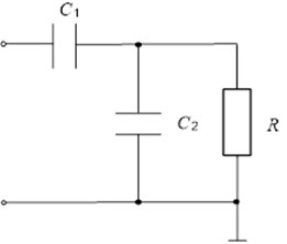
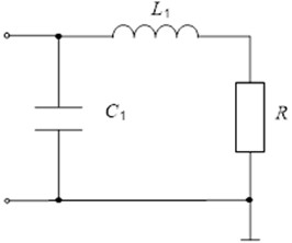
For this antenna, a three-band average input impedance equivalent was developed [3], which is used to measure the output power delivered by the R-134 radio station transmitter. Equivalent circuit diagrams [4] for the ranges of 1.5-6, 6-18, and 18-30 MHz are shown in Fig. 1. For the 1.5-6 MHz range, the circuit components (Fig. 1(a)) have the following values: C1 = 68 pF, C2 = 1720 pF; for 6–18 MHz: C1 = 112 pF, C2 = 290 pF; for 18-30 MHz (Fig. 1(b)): C2 = 33 pF, L1 = 1 μH. The resistor (R = 75 Ohm) is used for voltage measurement and conversion into the power delivered by the transmitter to the equivalent antenna [5].
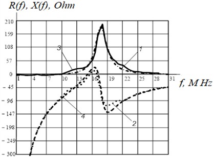
To assess the accuracy of the equivalents compared to the real antenna [6], Figs. 2-4 present frequency dependencies of the real and imaginary components of impedance from Table 1 (curves 1 and 2 respectively), along with the corresponding parameters of the equivalents (curves 3 and 4 respectively) [7].
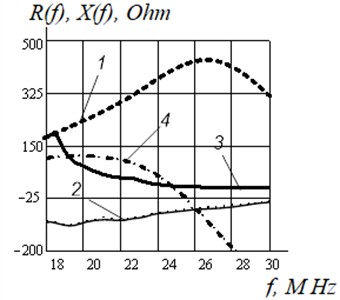
The analysis of these dependencies shows that in the ranges of 1.5-6 MHz and 6-18 MHz, only the real components of the equivalent impedance show acceptable proximity to the parameters of the real antenna [8]. In the range of 18-30 MHz, the correspondence between the equivalent and the real antenna is unsatisfactory. Therefore, there is an objective need to improve the input impedance model of the monopole antenna over a wide frequency range to enhance its accuracy [9].
Fig. 1ASh-4 antenna equivalent circuit layouts
a)
b)
Fig. 2Frequency characteristics of the wideband antenna equivalent in the 1.5-6 MHz range
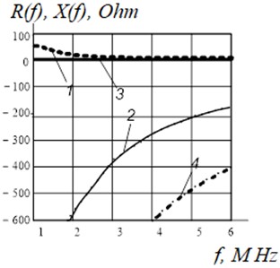
Fig. 3Frequency characteristics of the wideband antenna equivalent in the 6-18 MHz range
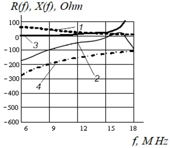
Fig. 4Frequency characteristics of the wideband antenna equivalent in the 18-30 MHz range
The existing modeling practice mostly involves selecting an appropriate circuit topology based on analytical expressions from literature [11] for the input impedance function of an antenna and using nonlinear optimization methods according to certain criteria to compute the circuit elements. However, convergence of such algorithms requires a good initial approximation. Moreover, the optimality of the chosen circuit topology remains an open question [12].
Another approach is based on interpolation methods, thoroughly investigated in [13]. These studies are particularly relevant as they were used to model a class of antennas similar to the short monopole type under consideration. The modeling process involves three sequential steps. In the first stage, the measured real part of the antenna impedance is interpolated using an even real function of input impedance. A minimum reactance function is then synthesized using the Gewertz method. In the second stage, the Foster part of the input impedance is interpolated. The sum of the resulting functions forms the complete input impedance function of the antenna. In the third stage, the circuit elements are synthesized [14]. The resulting model circuit is shown in Fig. 5. The parameters of the elements in this model are: 4 Ohm, 139 pF, 285 pF, 0.392 μH, 0.247 μH, 0.026 μH, 0.073 μH. Frequency dependencies of the impedance components of the model (curves 1 and 4) and the real antenna (curves 2 and 3) are presented in Fig. 6.
Fig. 5Yarman model for the impedance of a short monopole antenna
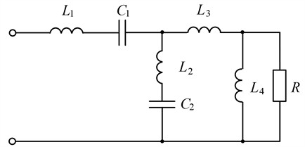
Fig. 6Frequency dependencies of the impedance components in the Yarman model
A key feature of the resulting model is the low load resistance (4 Ohm). Considering the characteristics of the antenna class under study, such resistance may be acceptable [15].
A distinctive feature of the resulting model is the low terminal load resistance (4 Ohms). Considering the characteristics of the antenna class under study, such resistance may be acceptable.
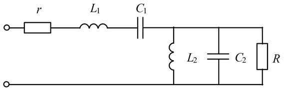
It is of interest to explore the possibility of applying a model originally developed for the input impedance of an RF transistor to this antenna. The basis for this assumption lies in the similarity of the frequency dependencies of the real and imaginary parts of the impedance. Both cases exhibit clear parallel and series resonances. This type of frequency behavior can be represented by the equivalent circuit shown in Fig. 7.
The real and imaginary parts of the impedance in the circuit shown in Fig. 7 are defined by the following expressions:
Based on Eqs. (1) and (2), the relationships for calculating the values of the model elements are derived:
where and are the frequencies of the series and parallel resonances, respectively; and are the frequencies selected in the regions of the dependencies where the influence of the corresponding model elements is significant.
Fig. 7Equivalent circuit of the input impedance
3. Results
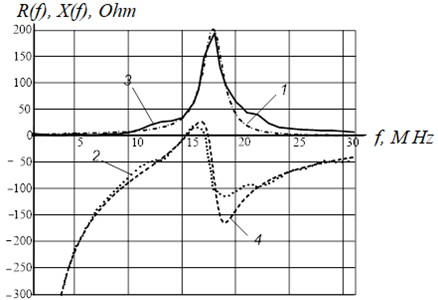
The obtained expressions can be used to calculate the values of the elements in the equivalent circuit shown in Fig. 7, which may serve as a good initial approximation for solving the interpolation task. The result of interpolation based on the measured impedance values from Table 1: 1.63 Ohm, 183 Ohm, 139 pF, 92 nH, 0.264 μH, 307 pF. Frequency dependencies of the active and reactive components of the model impedance (Fig. 7, curves 1 and 4 respectively) and the real antenna (curves 2 and 3 respectively) are shown in Fig. 8.
Fig. 8Frequency dependencies of the active and reactive impedance of the model from Fig. 7 and the real antenna
The frequency dependencies of the model in Fig. 7 provide a closer approximation to the measurement results. Unlike the Yarman model, this one features a higher load resistance. In solving the wideband matching problem, this model may be more preferable as it does not contain a transmission zero on the real frequency axis.
4. Discussion
One of the main ways to improve the technical characteristics of radio-electronic means (REM) is to improve their antenna systems. Today, trends related to the creation of short wave (SW) antennas for mobile radio communication facilities are relevant.
The whip antenna WA-4 monopolistic antenna (4 m long pin) is the most common antenna for HF radio stations, which refers to antennas of circular (omnidirectional) radiation, while the maximum radiation goes along the surface of the earth, and at the zenith the antenna practically does not radiate. The directivity of a monopolistic SW antenna can be calculated using formulas based on the size and structure of the antenna. Directivity is closely related to the antenna pattern, which is critical for optimal REM performance.
The WA-4 antenna, as a rule, is used in the entire frequency range of the radio facility together with the matching device (MD) located between the antenna itself and the main path of the radio electronic facilities. The MD takes into account changes in the operation of radio electronic facilities taking into account the operating conditions, and they are most effective in the operation of HF radio means. Impedance matching is critical to optimizing the power transfer between the antenna and the transmission line (or RF circuit). Analysis of the obtained dependencies of active and reactive input impedance allows us to conclude that the use of this antenna requires certain optimization. In particular, the use of such antennas requires matching devices with variable reactive elements, the parameters of which can be determined and optimized based on the dependence of resistance on the frequency of the antenna.
Note that a traditional monopolistic antenna usually suffers from narrow impedance bandwidth and low gain. The frequency dependencies of the active and reactive impedance models of the equivalent input impedance circuit and the real antenna (Fig. 8) confirm that it may be more preferable for broadband matching, since it does not contain zero transmission on the real frequency axis. Zero emission increases signal power for users, increases SNR (Signal-To-Noise Ratio), improves throughput and channel reliability, and reduces latency. Combined, these factors affect the overall performance of the system, eliminating the problems that need to be solved to ensure efficient and reliable communication in wireless networks.
5. Novelty
Further evolution of mobile radio communication systems is an important scientific and technical task that meets the current modern trends in the intensive introduction of the latest technologies. A special place in the design of REM is occupied by HF antennas, which are widely used in mobile radio communication facilities. These antennas can operate both in motion and in stationary mode. Information on the impedance of short-wave monopoly antennas of the considered HF range is found in available literary sources very rarely. In this paper, the equivalents of the electrical parameters of the real WA-4 antenna are determined by simulation. One of the important requirements in the design of matching devices is to establish the nature of the dependence of their impedance on the frequency. It is these requirements that determine the choice of the matching circuit and the ratings of the elements included in the antenna.
The developed schematic model of the hardware of the matching device is presented, using the equivalent schemes of the elements of the matching circuit (MC). In the design of the MD, real reactive elements are used, which emphasizes the need for the development of such a model. In this model, it is possible to vary the state of discrete sets of inductors and capacitors, thereby changing the equivalents of the circuit formed by the MC elements. On its basis, it is possible to calculate the resulting immitance at the MD input from the known antenna immitance. An experimental check of the match was carried out using a hardware mock-up of the MD and the equivalent of the WA-4 antenna. Accurate measurements of electrical parameters to verify the design of the monopoly antenna were obtained by the ZNB4 vector network analyzer.
The novelty lies in the fact that as a result of the research, the approach to the design of matching devices has been systematized and their structure has been revealed, which makes it possible to solve the problem of coordination for typical antenna systems of the HF range. The obtained new research results can be used for the construction of antenna devices of advanced radio-electronic means, since their Developments often (e.g., in the Internet of Things) place strict demands on stable and undistorted omnidirectional patterns at different frequencies within their operating bandwidths, as well as high impedance bandwidths.
6. Conclusions
The modeling results obtained for a specific type of short monopole antenna can be used to create impedance equivalents for the antenna, both across the full frequency range and within subranges. These models allow the application of modern wideband matching theory for antenna matching, as in demonstrated. Additionally, the development and manufacturing of antenna equivalents based on the modeling results (impedance equivalents for both the full frequency range and its subranges) can enable verification of design decisions during the conceptual and technical design phases of R&D projects for developing power amplifiers, antenna matching devices for modern radio stations operating in interference-protected software-defined frequency tuning modes.
References
-
M. A. Minkin and A. P. Trofimov, “Implementation of switchable matching devices for HF range based on half-sections and ladder filter segments,” (in Russian), Bulletin of SONIIR, Vol. 18, No. 4, pp. 84–88, 2007.
-
V. P. Belichenko, “Electrically small antennas: chronology, solved problems, new issues and ideas,” (in Russian), in 9th International Scientific and Practical Conference on Actual Problems of Radiophysics (APR-2021). Proceedings, pp. 55–60, 2021.
-
“Radio station R-134: technical maintenance manual product code 1.101.024,” (in Russian), 2001.
-
D. M. Sazonov, Antennas and Microwave Devices. (in Russian), Moscow, Russia: Higher School, 1988.
-
B. S. Yarman, A. Kilinc, and A. Aksen, “Immitance data modelling via linear interpolation techniques: A classical circuit theory approach,” International Journal of Circuit Theory and Applications, Vol. 32, No. 6, pp. 537–563, Nov. 2004, https://doi.org/10.1002/cta.295
-
B. S. Yarman, Design of Ultra Wideband Power Transfer Networks. Wiley, 2010, https://doi.org/10.1002/9780470688922
-
G. A. Filippovich and V. F. Belevich, “Modeling impedance based on measured S-parameters,” (in Russian), Bulletin of the Military Academy of the Republic of Belarus, Vol. 14, No. 1, pp. 34–38, Jan. 2007.
-
V. F. Belevich, “Wideband matching of loads with complex transmission zeros,” (in Russian), Collection of scientific papers, No. 19, pp. 73–77, Jan. 2010.
-
J. Plotkin, N. Almuratova, A. Yerzhan, and V. Petrushin, “Parasitic effects of PWM-VSI control leading to torque harmonics in AC drives,” Energies, Vol. 14, No. 6, p. 1713, Mar. 2021, https://doi.org/10.3390/en14061713
-
Yerzhan A. A. and Kuralbayev Z. K., “Electronic circuit responsiveness determination,” World Applied Sciences Journal, Vol. 26, No. 8, pp. 1011–1018, 2013.
-
I. Kozhabayeva et al., “Drone direction estimation: phase method with two-channel direction finder,” International Journal of Electrical and Computer Engineering (IJECE), Vol. 14, No. 3, p. 2779, Jun. 2024, https://doi.org/10.11591/ijece.v14i3.pp2779-2789
-
A. Yerzhan et al., “Method for design and implementation of telecommunication devices for aircraft,” International Journal of Electrical and Computer Engineering (IJECE), Vol. 14, No. 4, p. 4183, Aug. 2024, https://doi.org/10.11591/ijece.v14i4.pp4183-4194
-
S. A. Bahtaev, G. V. Bochkareva, and G. D. Musapirova, “Non-contact measurement meters of micro-sizes on coronary discharge,” News of the National Academy of Sciences of the Republic of Kazakhstan, Series of Geology and Technical Sciences of the Republic of Kazakhstan, Vol. 4, No. 424, pp. 208–218, 2017.
-
Z. Manbetova et al., “Method of undetermined coefficients for circuits and filters using Legendre functions,” International Journal of Electrical and Computer Engineering (IJECE), Vol. 15, No. 1, pp. 846–854, Feb. 2025, https://doi.org/10.11591/ijece.v15i1
-
A. Naizagarayeva et al., “Detection of heart pathology using deep learning methods,” International Journal of Electrical and Computer Engineering (IJECE), Vol. 13, No. 6, p. 6673, Dec. 2023, https://doi.org/10.11591/ijece.v13i6.pp6673-6680
About this article

This research was supported by the Science Committee of the Ministry of Science and Higher Education of the Republic of Kazakhstan under the project AP22686357 “Research and construction of an information system for processing nanosatellite orientation data based on filtration methods”. The authors would like to express their gratitude for the financial and organizational support provided.
The datasets generated during and/or analyzed during the current study are available from the corresponding author on reasonable request.
The authors declare that they have no conflict of interest.
