Abstract
Aiming at the problems of high cost of the mooring system, low utilization of sea area, and high environmental impact of the single floating wind turbine deployment mode, this paper takes the VolturnUS-S platform as the research object, and a hexagonal floating wind farm platform arrangement scheme is proposed. Based on the finite element method and hydrodynamic theory, the dynamic response characteristics of the new floating platform wind farm under normal operating conditions are studied. The results show that the main response mode of the floating platform is low-frequency response under normal operating conditions, the stability of the wind farm is better, and the mooring system meets the minimum safety factor requirement.
Highlights
- The multi-platform hexagonal configuration significantly improves overall heave stability compared to isolated single platforms.
- The system exhibits dominant low-frequency dynamic responses under normal operating conditions, ensuring motion stability.
- The mooring tension of the suspension lines on the windward side of the wind farm is the greatest.
1. Introduction
With the transformation of the global energy structure to cleaner and low-carbon sources, offshore wind power is gradually moving from offshore to deep and distant seas. In this process, floating wind power technology [1] has become the main direction for the development of offshore wind power because of its ability to break through the water depth limitation and develop richer wind energy resources in the deep and distant seas.
The traditional deployment mode of single floating wind turbines suffers from high costs of the mooring system, low utilization of sea area and high environmental impact, which limits the large-scale commercial application of floating wind power [2]. Scholars have started to study multiple turbine arrangements and their possibilities. Among them, Heronemus [3] first proposed the idea of arranging multiple wind turbines on a floating platform. Henderson et al. [4] innovatively designed a detached platform architecture, which can effectively stabilize the floating foundation and effectively improve the operational reliability and power generation efficiency of the units.
Floating wind farm platforms with shared mooring systems have begun to receive attention under multi-turbine arrangements. Fontana et al. [5] proposed a method to share the floating turbine moorings, which reduces the number of moorings across the platform. Goldschmidt et al. [6] simulated three example shared mooring arrays using both time and frequency domain methods and observed how the number of wind turbines affects the accumulation of mooring line thrust loads in wind farm headwinds. Hall et al. [7] conducted a dynamic characterization study of a floating wind turbine system with a four-unit square array and showed that the shared mooring system exhibits complex nonlinear restoring force characteristics and that the system’s intrinsic frequency is more likely to resonate with the environmental loads. Munir et al. [8] carried out a study on the dynamic characterization of a twin semi-submersible floating wind farm, focusing on the effects of the effect of different turbine spacing on the system performance, but the work only focuses on the platform motion analysis. Luan et al. [9] proposed a concentrically arranged floating truss octagonal platform system and considered the effect of the platform on the hydrodynamic performance and wave surface elevation. Based on the above research, this paper takes the 15 MW floating wind turbine VolturnUS-S platform as the research object, proposes a hexagonal floating wind farm platform arrangement scheme, and thoroughly studies the new floating wind farm platform and its dynamic response characteristics under normal operating conditions.
2. Model and methodology
2.1. Physical model
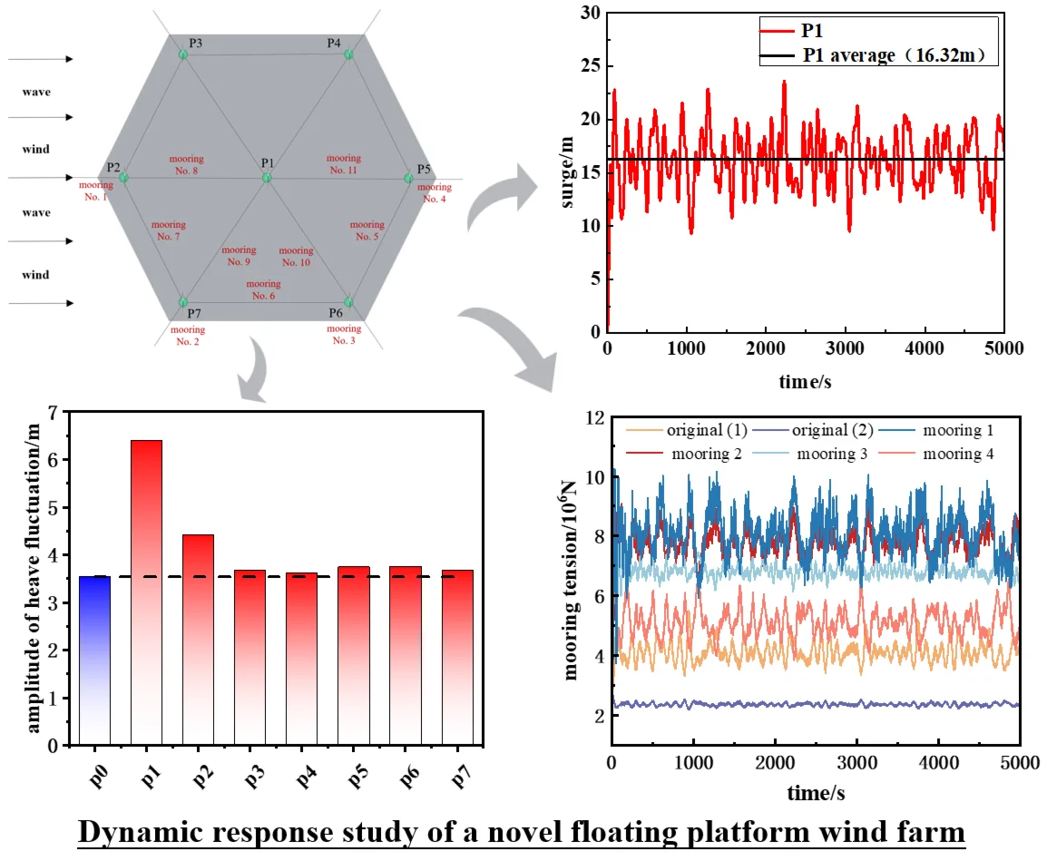
In this paper, the 15 MW floating turbine VolturnUS-S platform is used as the basis for constructing a seven-turbine floating wind farm, whose spatial layout is based on a centrally symmetric hexagonal array. The schematic diagram of the proposed floating wind farm platform is shown in Fig. 1, where the specific parameters of the VolturnUS-S platform have been described in the reference [10]. The spacing between neighboring wind turbines in the regular hexagonal floating wind farm is 1440 m.
Fig. 1Physical model of wind farm (unit: m)
a) Single platform model
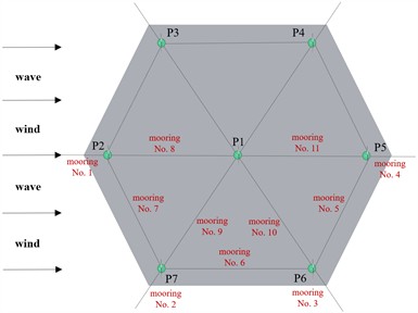
b) Overall schematic of the wind farm
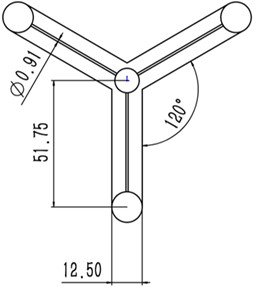
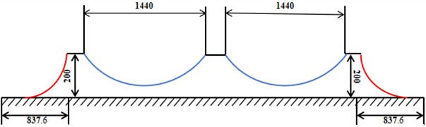
The mooring system of this wind farm consists of two types of fixed suspension chain lines (red) and shared suspension chain lines (blue), and the underwater local mooring schematic is shown in Fig. 2. The unit mass and equivalent volume diameter of the two types of suspension chain lines are 685 kg/m and 0.333 m, respectively.
Fig. 2Schematic of underwater localized moorings (unit: m)
2.2. Theory of environmental load calculation
Environmental load theory is a key component in the design and performance evaluation of floating wind turbines. It mainly consists of wind and wave load calculations under normal operating conditions. In this paper, the NPD wind spectrum is used to impose wind loads. In the NPD wind spectrum, the expression for the 1-hour mean wind speed at meters above sea level [11] is:
where, is the 1-hour average wind speed at 10 m above sea level.
The magnitude of the wind load is related to the shape factor and windward area of the structure subjected to wind action [12], calculated as:
where, is the wind load; is the design wind speed; is the height coefficient; is the shape coefficient; is the projected area of the wind-exposed component.
Based on the fluid mechanics principle of Bernoulli's equation [13], the fluid dynamic pressure exerted on a floating structure by wave loads can be obtained using the following formula:
The wave loads acting on a floating platform can be obtained by integrating the pressure on its wetted surface [14]. The corresponding mathematical expression is as follows:
where, is the excitation force caused by the incident wave; is the diffraction force; is the radiation force.
2.3. Loading conditions
In this paper, with reference to the research results of sea state in the South China Sea and the DNV specification, the loading conditions of normal operating conditions are defined, which correspond to the general sea state conditions in the South China Sea. The initial direction of wind and wave is 0°, the wind speed is 10.59 m/s, the significant wave height is 0.5 m and the spectral period is 7.0 s. Based on the JONSWAP wave model, an irregular wave train is generated, and combined with the NPD wind spectra to simulate the actual pulsating wind field. Different wave conditions and wind speeds are combined on the floating wind turbine in order to study the dynamic response and characteristics of the system.
3. Results and discussion
3.1. Reliability verification
In order to verify the accuracy of the numerical model, this paper carries out a comparative verification of the hydrodynamic performance of the VolturnUS-S platform. The computational model was established based on AQWA software, and the first-order wave excitation force of the platform was obtained by solving, which was then compared with the first-order wave force reference data calculated by the NREL team using WAMIT software. This, in turn, proved that the floating platform model established in this paper is accurate and reliable. The comparison results are shown in Fig. 3.
3.2. Platform surge, heave and pitch response
Traditional offshore engineering research mainly focuses on monolithic floating structures, whose mooring configurations are usually symmetrically arranged, and the extreme conditions of isotropic wind and wind waves are used as the design conditions. Therefore, the dynamic response analysis of the platform often focuses on the three degrees of freedom: surge, heave and pitch.
Fig. 3Comparative hydrodynamic data validation of platform models
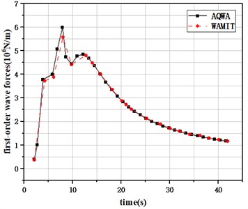
a) Surge first-order wave forces
b) Heave first-order wave forces
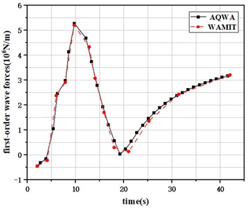
Under normal operating conditions, Fig. 4 demonstrates the time-frequency characteristic curves of the surge response of the floating wind farm with a regular hexagonal array semi-submersible platform. Considering the symmetrical distribution of the upper and lower side platforms about the x-axis, only the platforms at the centerline position (P1, P2, P5) and the upper side platforms (P3, P4) are analyzed in detail.
Fig. 4Time-domain characteristic curve of surge response of the platform under normal working condition
It can be seen from Fig. 4 that under normal operating conditions, the platform exhibits obvious dual-frequency motion characteristics under the action of wind and wave loads. Specifically, it is manifested as follows: the platform firstly generates obvious low-frequency displacement (the overall position undergoes persistent offset). Subsequently, periodic oscillations (wave-frequency response components) are formed near the average offset position.
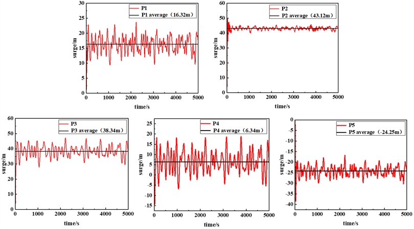
The statistical values of heave and pitch time-domain responses of the floating platform floating wind farm with regular hexagonal array under normal operating conditions are shown in Fig. 5. The displacement amplitude of the original single platform in the heave motion reaches 3.536 m. In the semi-submersible platform floating wind farm, the heave fluctuation amplitudes of the centerline platforms P1, P2, and P5 are 6.389 m, 4.419 m, and 3.745 m, respectively. Among them, the heave amplitude of P1 is significantly larger than that of the original single platform. This may be due to the fact that P1 is located at the center of the regular hexagon, where the vertical component of the mooring force is much smaller than that of the platform with the fixed suspension line, resulting in an increased wave response. However, the heave amplitude is still within the acceptable operating range of the turbine platform. In addition, the standard deviation of the heave response of each platform shows that P3, P4, P5, P6 and P7 are smaller than the original single platform, and only P1 and P2 are slightly higher than the original single platform. This indicates that the proposed wind farm is more stable in terms of heave motion response.
Fig. 5Statistical values of heave and pitch responses of the floating wind farm platform under normal operating conditions
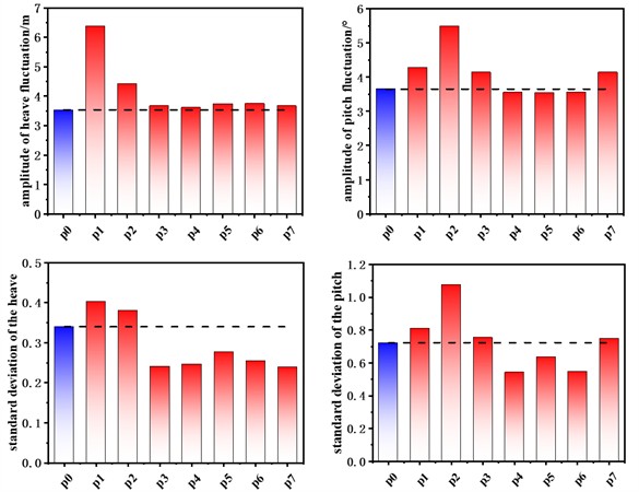
In terms of pitch response, the amplitude of pitch fluctuation of the original single platform is about 3.652°, and the amplitude of pitch fluctuation of platforms P1, P2, P3, and P7, which are close to the wind-wave side is slightly higher than that of the original single platform, while that of the platforms far away from the wind-wave side is slightly lower than that of the original single platform. In terms of the standard deviation of the pitch response, the standard deviation of each platform in the wind farm is consistent with the trend of the pitch fluctuation amplitude. This indicates that the pitch stability of the proposed wind farm is slightly lower than that of a single platform under normal operating conditions, but the overall performance is still relatively close.
3.3. Mooring system tension response
According to the CCS specification, under normal working conditions, the safety factor of the anchor chain has to meet the requirement of not less than 2.0 to ensure operational reliability. This safety factor is set to avoid failure of the anchor chain due to extreme loads or fatigue effects, thus ensuring the operational safety of the entire wind farm.
The schematic diagram of the proposed regular hexagonal array floating platform wind farm mooring system is shown in Fig. 1(b). Under the condition of wind wave incidence along the 0° direction, only the mooring tension data of one side needs to be analyzed as the mooring system is arranged symmetrically about the wind wave incidence direction. Under normal operating conditions, Fig. 6. compares the time history curves of the original individual VolturnUS-S platform 1 and 2 mooring tensions with the mooring tensions in the regular hexagonal array platform wind farm.
Fig. 6Floating wind farm platform mooring tension time history curve for normal operating conditions
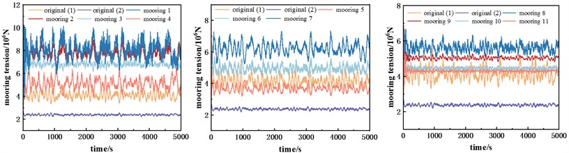
From Fig. 6, it can be seen that the mooring tension is highest on the windward wave side, followed by the intermediate position, while the fixed suspension chain line located on the right side has the lowest tension. Shared suspension chain lines on the outer and inner sides show a similar trend. In addition, the tension of fixed suspension chain lines No. 1, No. 2 and No. 3 was significantly higher than that of the other suspension chain lines, mainly due to the fact that the platforms to which these lines were attached were displaced more by the wind and waves, which resulted in a shorter length of the chain lines lying on the seabed, thus increasing the tension.
According to the analysis of the statistical values of mooring tension, the maximum value of mooring tension verifies the above law that the closer to the windward wave side, the smaller the mooring safety factor. The safety factors of all the suspension lines satisfy the minimum requirement of the CCS safety factor. By calculating the safety factor of the suspension lines, it can be seen that the safety factors of the original single platforms are 4.05 and 7.95, respectively, while the safety factor of mooring No. 1 in the multi-platform is the lowest, at 2.18. Therefore, the proposed regular hexagonal array floating platform wind farm mooring system shows good safety and reliability.
4. Conclusions
In this paper, the VolturnUS-S platform is the object of study, and an arrangement scheme for a hexagonal floating wind farm platform with a common mooring system is proposed. Based on the finite element method and hydrodynamic theory, the dynamic response characteristics of the new floating platform wind farm under normal operating conditions are investigated, and the following conclusions are drawn.
1) Under normal working conditions, the main response mode of the floating platform is low-frequency response. The wind farm configuration demonstrates improved heave stability for most platforms compared to a single unit, and while pitch response is slightly increased on the windward side, the overall system maintains good stability.
2) The mooring tension of the suspension lines on the windward side of the wind farm is the greatest. The closer to the windward side, the smaller the mooring safety factor. However, the safety factor of the entire mooring system suspension lines is greater than 2.0.
References
-
F. McAuliffe, F. Judge, and J. Murphy, “Modelling the installation of next generation floating offshore wind farms,” Applied Energy, Vol. 374, p. 124001, 2024, https://doi.org/10.1016/j.apener-gy.2024.124001
-
R. Chitteth Ramachandran, C. Desmond, F. Judge, J.-J. Serraris, and J. Murphy, “Floating wind turbines: marine operations challenges and opportunities,” Wind Energy Science, Vol. 7, No. 2, pp. 903–924, Apr. 2022, https://doi.org/10.5194/wes-7-903-2022
-
W. Stoddard, “The life and work of bill heronemus, wind engineering pioneer,” Wind Engineering, Vol. 26, No. 5, pp. 335–341, Sep. 2002, https://doi.org/10.1260/030952402321160633
-
A. Henderson, “Analysis tools for large floating offshore wind farms,” University College London, University of London, 2000.
-
C. M. Fontana, S. R. Arwade, D. J. Degroot, A. T. Myers, M. Landon, and C. Aubeny, “Efficient multiline anchor systems for floating offshore wind turbines,” in ASME 2016 35th International Conference on Ocean, Offshore and Arctic Engineering, Jun. 2016, https://doi.org/10.1115/omae2016-54476
-
M. Goldschmidt and M. Muskulus, “Coupled mooring systems for floating wind farms,” Energy Procedia, Vol. 80, pp. 255–262, Jan. 2015, https://doi.org/10.1016/j.egypro.2015.11.429
-
M. Hall and P. Connolly, “Coupled dynamics modelling of a floating wind farm with shared mooring lines,” in ASME 2018 37th International Conference on Ocean, Offshore and Arctic Engineering, Jun. 2018, https://doi.org/10.1115/omae2018-78489
-
H. Munir, C. F. Lee, and M. C. Ong, “Global analysis of floating offshore wind turbines with shared mooring system,” in IOP Conference Series: Materials Science and Engineering, Vol. 1201, No. 1, p. 012024, Nov. 2021, https://doi.org/10.1088/1757-899x/1201/1/012024
-
Z. Luan et al., “Research on wavestar-like wave energy converter arrays with a truss-type octagonal floating platform in the South China Sea,” Energy, Vol. 313, p. 134070, Dec. 2024, https://doi.org/10.1016/j.energy.2024.134070
-
C. Allen et al., “Definition of the UMaine VolturnUS-S reference platform developed for the IEA wind 15-megawatt offshore reference wind turbine: IEA wind TCP task 37,” National Renewable Energy Lab, NREL/TP-5000-76773, 2020.
-
M. Zhang, J. Zhang, H. Chen, X. Xin, Y. Li, and F. Jiang, “Probabilistic wind spectrum model based on correlation of wind parameters in mountainous areas: Focusing on von Karman spectrum,” Journal of Wind Engineering and Industrial Aerodynamics, Vol. 234, p. 105337, Mar. 2023, https://doi.org/10.1016/j.jweia.2023.105337
-
Y. Wu, C. Ma, P. Miao, X. Han, and Y. Liu, “Influence of opening rate and opening position on wind load and aerodynamic stability of long-span truss roof structure,” Journal of Fluids and Structures, Vol. 133, p. 104268, Mar. 2025, https://doi.org/10.1016/j.jfluidstructs.2025.104268
-
S. Hutahaean, “Correlation of weighting coefficient at weighted total acceleration with Rayleigh distribution and with Pierson-Moskowitz spectrum,” International Journal of Advanced Engineering Research and Science, Vol. 6, No. 3, pp. 249–252, Jan. 2019, https://doi.org/10.22161/ijaers.6.3.33
-
J. Wang et al., “Investigation of second-order low-frequency wave forces approximations for moored floating structures,” Ocean Engineering, Vol. 282, p. 114987, Aug. 2023, https://doi.org/10.1016/j.oceaneng.2023.114987
About this article

The authors have not disclosed any funding.
The datasets generated during and/or analyzed during the current study are available from the corresponding author on reasonable request.
The authors declare that they have no conflict of interest.
