Abstract
With the development of high-speed trains, the requirements for noise, vibration, and comfort are becoming increasingly stringent. The train body floor, as one of the main pathways for vibration transmission, is crucial to be treated for vibration reduction and noise attenuation. This paper, in response to this demand, has developed a new type of floor vibration isolator specifically for high-speed trains. Through finite element simulation analysis and experimental verification, it has been proven that this vibration isolator can effectively reduce the vibration of the train body floor and significantly enhance the NVH (Noise, Vibration, and Harshness) performance of the train.
1. Introduction
The noise, vibration, and harshness of high-speed trains directly affect the passenger experience and the operational safety of the train. As the speed of the train increases, vibration and noise problems become more prominent [1]. The floor, as one of the main pathways for vibration transmission, directly affects the acoustic environment inside the carriage and the comfort of passengers. Therefore, effective vibration reduction and noise attenuation treatment of the floor is a key link in improving the NVH performance of high-speed trains [2].
Traditional floor vibration isolators are mostly made of rubber or spring materials [3]. Although they can reduce vibration to a certain extent, their vibration isolation effect is limited under low-frequency, high-load conditions. In recent years, with the development of material science and computational technology, the design of new vibration isolators has gradually evolved towards high performance, lightweight, and intelligent directions [4].
Therefore, the development of an efficient floor vibration isolator is of great significance for improving the NVH performance of trains. This paper introduces the design and verification process of a new type of floor vibration isolator specifically for high-speed trains, including finite element simulation analysis and experimental verification. The vibration isolator adopts a hydraulic form and has the following characteristics [5-6]:
– Low-frequency, high-amplitude: Under low-frequency, high-amplitude excitation, the hydraulic mount generates a large damping through the inertial channel, effectively absorbing vibration energy.
– High-frequency, low-amplitude: Under high-frequency, low-amplitude excitation, the dynamic stiffness of the hydraulic mount is significantly reduced. Meanwhile, the inertial channel self-locks, and the pressure balance is achieved through the decoupling membrane, thereby reducing the transmission of high-frequency vibrations.
The vibration isolator consists of an upper fluid chamber and a lower fluid chamber. When the vibration isolator is subjected to low-frequency, high-amplitude excitation, the decoupling membrane is in a closed state. At this time, the fluid flows back and forth between the upper and lower fluid chambers through the inertial passage. When the vibration isolator is subjected to high-frequency, low-amplitude excitation, the inertial passage is in a closed state. At this time, the fluid flows back and forth between the upper and lower fluid chambers through the gaps around the decoupling membrane.
2. Finite element simulation analysis
2.1. Description of the finite element model
The overall dimensions of the hydraulic vibration isolator are as follows: length 130 mm, height 38 mm, width 75 mm, and weight 0.3 kg. The vibration isolator was meshed using the finite element software HyperMesh. Tetrahedral elements were employed for meshing. The average element size for the rubber part was 0.5 mm, and the rubber constitutive relationship was modeled using the Mooney-Rivlin model, The five-parameter Mooney-Rivlin model for rubber is a constitutive model used to describe the hyperelastic behavior of rubber materials under large deformations. It can more accurately describe the stress-strain relationship of rubber materials under different loading paths and is capable of effectively simulating the nonlinear mechanical behavior of rubber materials, with parameters as shown in Table 1.
Table 1The parameters of the Mooney-Rivlin model for rubber
Parameters | Values / MPa |
C10 | –0.55 |
C01 | 0.7 |
D1 | 0.001 |
C20 | 1.7 |
C11 | 2.5 |
C02 | –0.9 |
The average element size for the aluminum alloy frame was 1.5 mm, and the material parameters for the aluminum alloy are presented in Table 2.
Table 2The parameters of the aluminum alloy
Parameters | Values |
Elastic modulus | 70 GPa |
Poisson's ratio | 0.33 |
Density | 2.7E-9 t/mm3 |
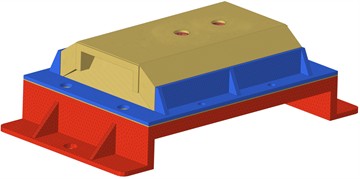
The total number of elements in the vibration isolator mesh was 1,183,389. The finite element model of the vibration isolator is shown in Fig. 1.
Fig. 1The external shape of the vibration isolator
2.2. Finite element simulation and results
To ensure the comparability between the simulation and test results, the vibration isolator was carefully modeled and analyzed in the finite element software. Specifically, the boundary conditions applied to the vibration isolator in the simulation were meticulously set to match those of the static stiffness test. This included constraining the base of the isolator to prevent any translational or rotational movement, thereby simulating the fixed mounting conditions typically encountered during the static stiffness testing process. Additionally, the loading conditions were precisely replicated, with the same magnitude and direction of force applied to the top surface of the isolator as specified in the test protocol. By strictly adhering to these boundary and loading conditions in the finite element analysis, the simulation results were able to closely mirror the actual behavior of the vibration isolator observed during the static stiffness test, thereby ensuring a high degree of comparability between the two sets of results.
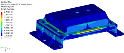
The two bolt holes of the vibration isolator base were constrained (SPC123456), and a forced displacement of 2.7 mm in the vertical downward direction was applied to the top cover of the vibration isolator. The nodal forces at the location where the displacement was applied were then output. Finally, the model was submitted to Optistruct for nonlinear calculation. The stress contour map is shown in the Fig. 2, with the maximum stress being 27.1 MPa. The safety factor at this time is 2.03 which meets the design requirements.
Fig. 2The stress contour map of the vibration isolator
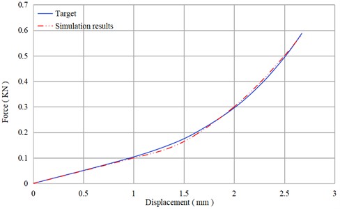
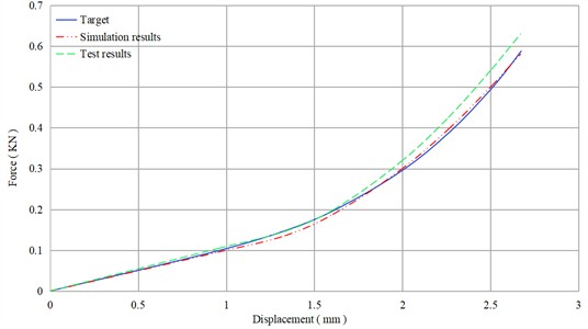
The force-displacement curve calculation results are shown in Fig. 3, and the simulation results are in good agreement with the design objectives.
Fig. 3Force-displacement curve of the vibration isolator
3. Experimental verification
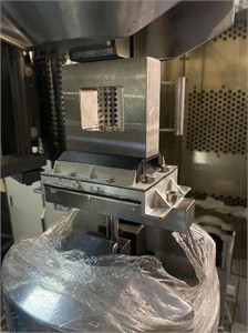
After the prototype is manufactured, the initial evaluation of its mechanical properties begins with the static stiffness test, which is meticulously carried out on the MTS testing platform, as illustrated in Fig. 4. This platform is renowned for its precision and reliability in conducting mechanical tests, making it an ideal choice for assessing the static stiffness of the prototype. To ensure the accuracy and consistency of the test results, a thorough pre-test conditioning process is essential. Specifically, the specimen should be subjected to at least five cycles of loading prior to the formal test. This conditioning process is crucial as it helps to eliminate any initial gaps and residual stresses that may exist between the components of the prototype. These gaps and stresses can arise during the manufacturing process and, if not addressed, can significantly affect the test outcomes. During the pre-test cycles, the specimen is carefully loaded and unloaded, allowing it to settle into a more stable state. This step is critical in ensuring that the test results reflect the true mechanical behavior of the material under study, rather than transient effects caused by initial imperfections. Furthermore, the environmental conditions of the testing environment are also carefully controlled to maintain a consistent temperature and humidity, as these factors can influence the mechanical properties of the material.
Fig. 4The static stiffness test of the vibration isolator
The force-displacement curve is output, as shown in Fig. 5. It can be seen from the figure that the measured displacement-force curve of the vibration isolator is in high agreement with the design target, meeting the design requirements and thereby verifying the effectiveness of the finite element simulation method.
Fig. 5The static stiffness test results of the vibration isolator
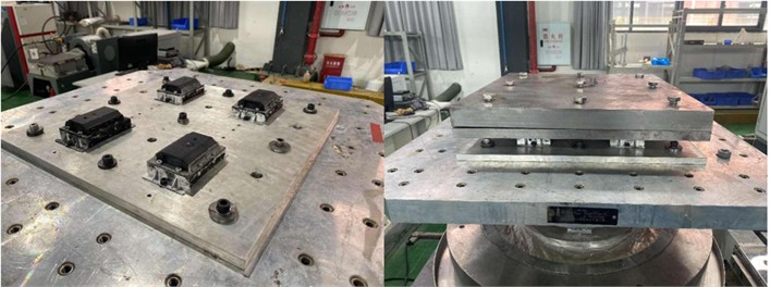
To fully validate the vibration isolation performance of the vibration isolator, vibration tests need to be conducted on a shaker table. In this test, four vibration isolators were rigidly attached to the shaker table surface, and a high-rigidity mass block weighing 120 kg was rigidly connected to the upper end of the vibration isolators. This mass block serves as the load. The test setup is shown in the Fig. 6.
To truly assess the actual working performance of the vibration isolator under realistic operating conditions, a highly representative excitation signal was utilized in this test. Specifically, the excitation signal employed was the real-time measured vibration acceleration signal of the vehicle body, which captures the dynamic interactions and vibrations experienced during actual vehicle operation. This signal encompasses a broad frequency range of 0-500 Hz, ensuring that the vibration isolator is subjected to a comprehensive spectrum of vibrations that it would typically encounter in service. By using such a realistic excitation signal, the test aims to evaluate how effectively the vibration isolator can attenuate vibrations across different frequencies, thereby providing a true reflection of its performance in real-world applications.
Fig. 6Vibration isolation performance test of the vibration isolator
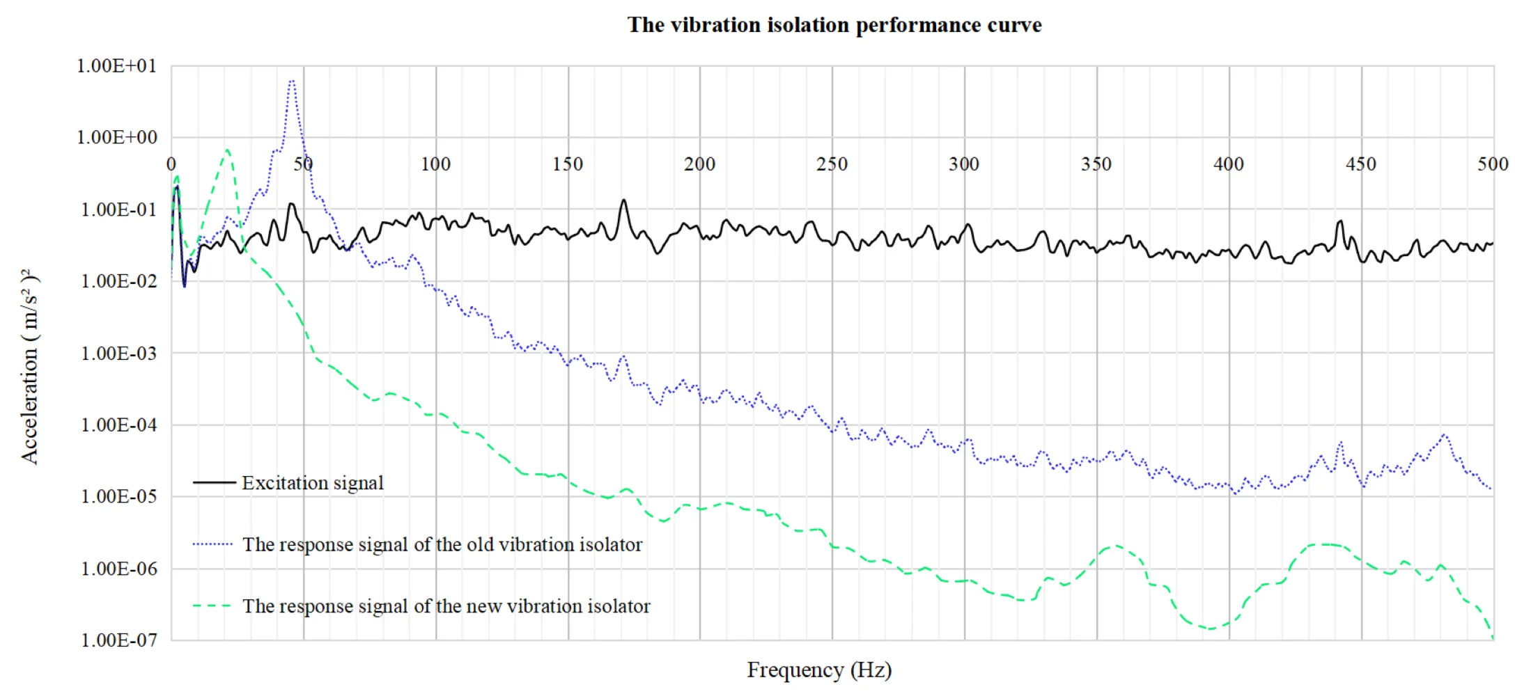
The test results, which reveal the vibration isolator's response to this complex and realistic excitation, are presented in Fig. 7. This figure provides a detailed visualization of the isolator’s performance, showing how it handles the input vibrations across the entire frequency range. The data in Fig. 7 not only highlight the isolator's effectiveness in reducing vibrations at critical frequencies but also demonstrate its overall robustness and reliability under dynamic conditions. By analyzing these results, valuable insights can be gained into the vibration isolator’s ability to protect the vehicle structure and improve ride comfort, ultimately contributing to the optimization of its design and performance.
Fig. 7The vibration isolation test results of the old and new vibration isolators
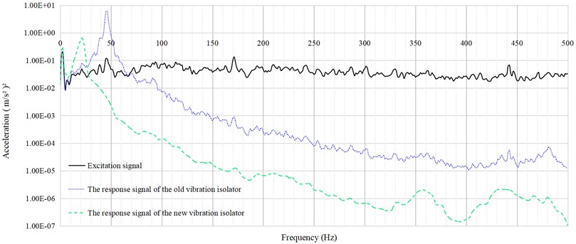
The test results indicate that the vibration isolation efficiency of the new vibration isolator is significantly higher than that of the old one. In the mid-to-high frequency range (50-500 Hz), it demonstrates excellent vibration isolation performance. This suggests that the new vibration isolator can effectively reduce floor vibrations and enhance the NVH (Noise, Vibration, and Harshness) performance of the train.
4. Conclusions
Through finite element simulation analysis and experimental verification, it has been proven that the newly developed floor vibration isolator for high-speed trains meets the design requirements. It outperforms traditional vibration isolators in terms of vibration isolation performance, effectively reducing floor vibrations and noise, the vibration isolation performance has been improved by more than 20 %, thereby enhancing the NVH (Noise, Vibration, and Harshness) performance of the train. The new vibration isolator achieves high vibration isolation efficiency across a broad frequency range, with particularly significant isolation effects in the high-frequency band. In the future, this type of vibration isolator is expected to be widely applied in high-speed trains, providing passengers with a more comfortable and quieter riding environment. Additionally, the technical approach and methods employed in this study offer valuable references for the design of other types of vibration isolators.
References
-
Y. Zhang and J. Smith, “A review of noise and vibration control technologies for high-speed trains,” Journal of Sound and Vibration, Vol. 500, No. 15, p. 11602, 2023.
-
H. Lee and S. Kim, “Vibration isolation strategies for high-speed train bogies,” International Journal of Vehicle Design, Vol. 92, No. 15, pp. 123–145, 2022.
-
J. Park and Y. Choi, “Advanced materials for noise reduction in high-speed train cabins,” Composites Part B: Engineering, Vol. 256, No. 15, p. 11058, 2023.
-
J. Wu and L. Chen, “Vibration transmission path analysis in high-speed train carbodies,” Journal of Vibration and Control, Vol. 29, No. 16, pp. 1857–1872, 2023.
-
J. H. Zhang and J. Liu, “Design and analysis of a novel semi-active hydraulic engine mount for enhanced NVH performance,” Nonlinear Dynamics, Vol. 108, pp. 3417–3434, 2022.
-
T. Q. Truong and K. K. Ahn, “A new type of semi-active hydraulic engine mount using controllable area of inertia track,” Journal of Sound and Vibration, Vol. 329, No. 3, pp. 247–260, Feb. 2010, https://doi.org/10.1016/j.jsv.2009.09.015
About this article

The authors have not disclosed any funding.
Authors would like to extend special thanks once again to the “Development Project of Variable Stiffness and Variable Damping Floor Vibration Isolator” for its support of this thesis.
The datasets generated during and/or analyzed during the current study are available from the corresponding author on reasonable request.
The authors declare that they have no conflict of interest.
