Abstract
Spherical plain bearings play an important role in aircraft control systems because of their excellent load-carrying capacity. However, the difficulties in controlling the installation process and detecting the installation effect have been the key issues limiting the product yield. According to the problems of low installation efficiency and poor quality consistency that exist in the traditional punching point installation method, this study analyzes the key installation process of bearings and summarizes the two major factors, the punching point position and the punching point depth, affecting the installation quality of bearings. A six-point punching point installation tool with a punching point depth/position control structure is designed to greatly improve the installation quality and efficiency of bearing installation. For evaluating the installation effect of bearings, this paper develops a kind of spherical plain bearing starting torque automatic detection equipment with the dual drive system, which adds the oscillating torque measurement function in addition to the rotating torque detection function and realizes the automated and comprehensive detection of the starting torque of bearings with a single clamping.
1. Introduction
As an important part of the mechanical driving system, the spherical plain bearings are widely used in aerospace, robotics, and other high-end equipment fields for their advantages of impact resistance, corrosion resistance, and high load-carrying capacity [1-3]. Its installation quality directly affects the load capacity, service life, and equipment reliability of the bearings. With the development of modern industry in the direction of high precision, high reliability, and intelligence, the application field of spherical plain bearings has become increasingly complex, which puts forward higher requirements for its installation reliability and post-installation performance. For example, in extreme temperatures, heavy load impact, or strong corrosive environments, a minor deviation in the installation procedure may lead to premature failure of bearings, which may lead to equipment malfunction. For this reason, many scholars have carried out research on the installation of spherical plain bearings. Xu et al. [4] designed the spherical plain bearing flanging tooling, which overcomes the difficulties of offset and misalignment that are easy to occur in the process of flanging. Song et al. [5-6] designed an automatic assembly machine for spherical plain bearings, which adopts pneumatic-hydraulic force amplification transmission and the maximum pressure value limitation method to control the assembly pressure and ensure the precision of spherical plain bearings’ outer ring flanging and crimping. Tang et al. [7] conducted simulation analyses and experimental validations on installation tools of different specifications, providing theoretical support for bearing crimping. Compared with the installation method of flanging, using the punching point method to install the bearings can effectively reduce the deformation of the outer ring of the bearings in the process of fixing, which can reduce the positive pressure between the bearing liner and the inner ring, and effectively ensure the rotational and oscillating performance of the bearings. However, the traditional punching point method of fixing spherical plain bearings mainly adopts a manual installation process, supplemented by empirical manual adjustment and checking, and lacks similar tools such as flanging and crimping, which excessively relies on the operator's skill level and experience in checking, having significant limitations.
To ensure that the installation of bearings can satisfy the requirements of actual working conditions, according to the aviation equipment manufacturing standards, the starting torque of spherical plain bearings needs to be detected after the installation of bearings to check the quality of bearing installation and to ensure the reliability of bearing performance. Ji et al. [8] designed a spherical plain bearing friction torque detecting device, which is used for the measurement of bearing performance indicators such as bearing friction torque measurement. Liu et al. [9] proposed a method to improve the calibration accuracy of torque sensor calibrators and provided a theoretical basis for the low friction optimization design of deep groove ball bearings. Wu et al. [10] analyzed the development of theoretical formulas for the frictional torque of rolling bearings and summarized the corresponding methods for torque measurement. Although the aforementioned studies have provided a theoretical basis and measurement methods for the detection of the starting torque for bearings, most of the current studies on the detection of the starting torque for bearings only focus on the rotational torque. However, in actual working conditions, insufficient flexibility of the bearing oscillation will also paralyze the operating system, so how to realize the comprehensive measurement of the rotation torque and oscillation torque of the bearing after installation has become a key issue that needs to be solved urgently.
This paper analyzes the common punching point installation method - six-point installation, summarizes the difficulties and shortcomings of the traditional manual punching point installation, and develops a six-point punching point installation tool with a punching point depth/position control structure considering the two key process parameters of indentations position and indentations depth. This device effectively solves the problems of long cycles of manual work, and difficulty to control the position and depth of the punching point, and greatly improves the installation quality and efficiency of bearings. In addition, this study combines the actual working conditions of spherical plain bearings, proposing a spherical plain bearing starting torque automatic detection equipment with a dual drive system. It realizes the function of measuring the rotating torque and oscillating torque of bearings with a single clamping, which meets the demand of reliability detection of bearing installation quality as well as effectively simplifies the difficulty of torque measurement, providing a new solution for the detection of starting torque of spherical plain bearings.
2. Research on spherical plain bearing installation issues
2.1. Analysis of installation challenges
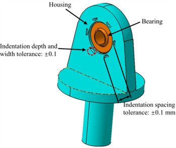
When using the six-point installation method to fix the spherical plain bearings, it needs to punch 6 crescent-shaped indentations (a total of 12 on the front and rear sides) on the edge of the installation hole. So that the edges of the hole can be deformed and the housing material will be filled into the gap between the bearing and the housing hole to hold the bearing. The installation specifications are shown in Fig. 1.
The 12 crescent-shaped indentations are manually stamped by operators using a punch. The spacing and depth of these crescent-shaped indentations rely entirely on the operator’s skill. The uncontrollable nature of manual hammering force from operator arm movements results in inconsistent indentation depths across the 12 locations.
Bearing indentation depth cannot be directly measured, so operators must first measure indentation width, then locate the corresponding width marking on the punch tool, and finally measure the distance between the marked position and the punch tip to indirectly determine depth. Clearly, this indirect measurement method lacks accuracy and presents quality risks. In addition, when the location of the indentation is far from the edge of the hole and the depth of the pit is insufficient, the bearing will not be fixed in the housing hole, which poses a risk of dislodging in operation and affects the safety of the system.
Fig. 1Installation requirements for bearings
In summary, manual bearing installation presents the following potential problems:
1. Poor quality consistency.
2. Difficulty in measuring indentation depth and width.
3. Incorrect indentation location and depth will affect the safety of the system.
2.2. Compression force calculation
The installation tool requires a stable pressure source, and before determining the pressure source, the required clamping force for clamping and fixing the bearing must be calculated. Finite element simulation is used to simulate the punch extrusion process and calculate the required clamping force. In the finite element model, the operating system parts are simplified, and only the tip position of the punch is selected. The mesh of the clamping area is refined to ensure calculation accuracy.
This article establishes a finite element model of a single punch squeezing a crescent shaped indentation using ABAQUS finite element software, and calculates the required clamping force. The finite element model mesh adopts a three-dimensional stress hexahedron C3D8R and an eight node linear hexahedral element. In the finite element model, the mesh division of the simplified part is discretized into 48510 mesh elements using a free mesh method, with a refined position element length of 0.1 mm; the punch is discretized into 6929 mesh elements using a free mesh method, with an element length of 0.2 mm. The finite element model is shown in Figure 4. Under initial conditions, the simplified operating system part adopts binding constraints on the bottom surface, fixing the degrees of freedom in six directions to avoid displacement of the part during simulation. The punch is bound and constrained into a rigid body, assuming that it will not undergo deformation or wear. When simulating the extrusion process with finite element method, there is friction between the punch and the part. This friction is decomposed into normal and tangential directions in ABAQUS. The common practice is to define normal friction as zero and tangential friction as penalty friction, with a friction coefficient generally taken as 0.3.
According to the analysis results (Fig. 2), a single punch requires a clamping force of not less than 6000 N, and 6 punches require a clamping force of not less than 36000 N. Choose a hydraulic vise that meets the pressure requirements, model: CHY-130A, it can provide a maximum clamping force of 46000 N
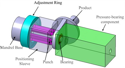
2.3. Installation tool improvement
The developed installation tool (Fig. 3) integrates a core shaft base and pressure-bearing component connected to a hydraulic vise. The vise provides clamping force transmitted through the core shaft base and adjustment rings to the punch, forming precise crescent-shaped indentations. Standardized punch structures made of high-speed steel W18Cr4V (hardness HRC63-66) ensure durability. The core part of the punch is pointed, and its shape is designed according to the shape of the indentation. The gap adjustment range of the gasket should not be too large, generally within 0.5 mm. A positioning sleeve and adjustment ring control indentation positions and depths. By utilizing adjustment shims of varying thicknesses in conjunction with the mandrel base and locating sleeve to secure and regulate punch protrusion length, this configuration ensures adequate extrusion depth is achieved.
Fig. 2Stress cloud map and compression force calculation results
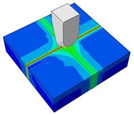
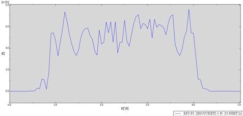
Fig. 3Overall structure of the bearing installation tool
2.4. Tool performance validation
Using the newly developed bearing installation tool for assembly, and tracking the bearing installation of multiple batches of parts, all checked the indentation depth, location, and press-out force when using the tool to press the fixed bearing. The results show that: after using the developed bearing installation tool, the qualification rate of bearing installation reaches 100 %, and the bearing press-out test is 100 % qualified, confirming the tool’s effectiveness.
3. Post-installation performance detection technology
3.1. Detection System Design
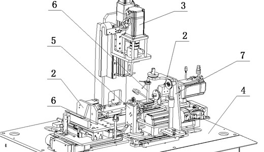
The automated detection system (Fig. 4) comprises rotational torque detection, oscillating torque detection, a device frame, positioning fixtures, transducer modules, and calibration components. It enables the measurement of two torques in a single clamping.
The clamping system is used to clamp the product, while the oscillating torque detection system and the rotating torque detection system correspond to the torque detection. A torque calibration system verifies measurement accuracy across the systems. The integrated detection system consists of the following modules:
(1) A horizontally arranged inner ring rotational drive system mounted on the test bench platform.
(2) A vertically configured inner ring oscillation drive system installed on the test bench platform.
(3) The fixture system positioned on the test bench platform.
The system has designed a torque calibration structure that converts standard weight weights into torque to compare the error between measured torque and theoretical values.
Fig. 4Overall structure of the torque detection system: 2 – rotating torque detection system; 3 – oscillating torque detection;4 – device frame; 5 – clamping system; 6 – transducer modules; 7 – torque calibration system
3.2. Automated control system
A PLC-controlled system drives servomotors, pneumatic chucks, and electric slides to generate relative rotation or oscillation between bearing inner and outer rings. Real-time torque data is collected via torque transducers and angle feedback from servomotors. The detection system comprises four subsystems: rotational torque detection system, oscillation torque detection system, clamping system, and detection control system. The logic of the system structure is shown in Fig. 5.
Fig. 5Logic diagram of the detection system
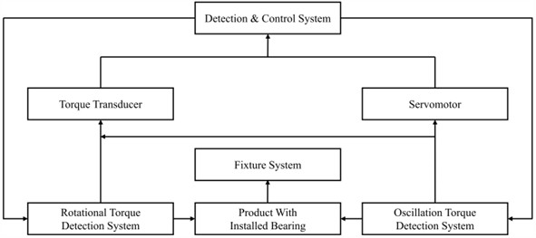
With the ingenious structural design, the PLC program drives the electrical and mechanical structures sequentially, this automated system achieves comprehensive torque measurement (both rotational and oscillation) within a single clamping operation.
During rotational torque measurement:
(1) The detection control system activates the rotational torque detection system.
(2) Drives inner ring rotation within the stationary outer ring.
(3) The outer ring remains fixed to the product via the clamping system.
During oscillation torque measurement:
(1) The oscillation torque detection system engages.
(2) Induces inner ring oscillation within the stationary outer ring.
(3) The outer ring maintains fixation through the clamping system.
Signal feedback architecture:
(1) Torque transducers in both drive systems transmit torque values to the control system.
(2) Servomotors in both drives provide angular displacement feedback.
Automated detection control sequence:
(1) Position the rotational torque detection system at predetermined coordinates.
(2) Manually clamp product using rotational system's mandrel and face alignment.
(3) Activate servo-driven linear guides per pre-programmed routines.
(4) Overcome bearing start-up torque through controlled drive torque.
(5) Acquire synchronized feedback:
– Torque signals via torque transducers.
– Angular data via servo encoders.
– Real-time display through the host computer interface.
According to the design requirements, NS-NJ7-2Nm dynamic torque sensor was selected. The measurement range of this sensor is 0-2 Nm, with an accuracy level of ±0.2 % F·S and a repeatability accuracy of ±0.02 % F·S. The key parameters for measuring rotational torque include: 1) using RPM units (range 10-100 rpm) for speed, which is monitored in real-time through an encoder; 2) The starting torque is measured using the NS-NJ7-2Nm high-precision torque sensor (measuring peak and steady-state values; 3). The oscillation parameters are set according to QC/T 73-2017 standard, and the sampling frequency is ≥ 50 Hz.
3.3. System implementation
The developed system (Fig. 6) automates torque and flexibility checks for installed bearings, outperforming market devices limited to rotational torque measurement.
Fig. 6Bearing flexibility detection system
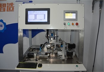
a) Physical configuration photo
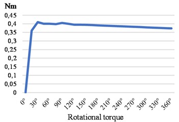
b) Test result curve
4. Results
(1) The performance comparison between traditional manual methods and newly installed tools is shown in Table 1.
(2) The average and standard deviation of the rotational torque values of a batch of test parts were statistically analyzed, with a data range of 0.36-0.405 Nm. The calculated average value was 0.3895 Nm, the standard deviation was 0.0107 Nm, the median was 0.3892 Nm, and the coefficient of variation (CV) was 2.76 %.
Table 1Performance comparison between traditional manual methods and new installation tools
Performance index | Traditional manual methods | New installation tool |
Average installation time | 30±10 minutes per piece | 5±2 minutes per piece |
Consistency of positioning accuracy | Mean value 0.18 mm, standard deviation ± 0.03 mm | mean value 0.10 mm, standard deviation ± 0.01 mm |
Stability of compression force | 91 % | 100 % |
5. Conclusions
1) According to the material hardness of the product, high-speed steel W18Cr4V was selected as the material of the punch, and an installation tool with the punch point depth/position control structure was developed.
2) The installation tools have significantly improved efficiency and qualification rate, and can be widely promoted in the aviation equipment repair industry; However, the tool still lacks work pressure figures and will be further studied.
3) Established detection control system design and overall structural design of the detection system, and the developed equipment can achieve the comprehensive detection of starting torque by single clamping, which meets post-installation oscillating and rotational torque testing requirements.
4) The tool and system demonstrate innovation and practicality, and the corresponding technology has been previously protected by three invention patents.
5) The installation and post installation performance testing technology of bearings has certain reference value for the research on the flexibility of robotic arms in small robots and the assembly of high-speed bearings in new energy vehicles.
References
-
H. T. Chen, L. L. Zhu, X. R. Huang, J. J. Zhang, and C. L. Hu, “Effect of stress during press-fitting on tribological behavior of self-lubricating composite liners in spherical plain bearings,” Materials Science Forum, Vol. 1147, pp. 55–62, Mar. 2025, https://doi.org/10.4028/p-r34ydh
-
Z. Jiang et al., “The grinding efficiency and surface roughness study of WC-10Co-4Cr coating on the spherical plain bearings based on the trajectory analysis,” International Journal of Precision Engineering and Manufacturing-Green Technology, pp. 1–12, Apr. 2025, https://doi.org/10.1007/s40684-025-00709-0
-
Y. Liu et al., “A new coated self-lubricating spherical plain bearing with high performance and excellent security,” Proceedings of the Institution of Mechanical Engineers, Part J: Journal of Engineering Tribology, Vol. 238, No. 1, pp. 60–72, Sep. 2023, https://doi.org/10.1177/13506501231203034
-
T. T. Xu, K. P. Ouyang, and L. Feng, “Flanging tool for spherical plain bearings,” Chinese Utility Model Patent, 2016.
-
B. W. Song and Q. Y. Geng, “Development of an automatic assembly machine for spherical plain bearings,” Aeronautical Manufacturing Technology, No. S1, pp. 171–173, 2014.
-
B. W. Song, X. H. Cao, and H. Z. Deng, “Automatic assembly machine for spherical plain bearings,” CN101290028A, Chinese Invention Patent, 2008.
-
H. Tang, L. An, H. Hu, H. Zhang, J. Liu, and W. Zhang, “Simulation analysis of installation fixation and push-out for self-lubricating spherical plain bearings with annular grooves,” Technology Innovation and Application, Vol. 14, No. 10, pp. 63–66, 2024.
-
Y. Ji, X. M. Zong, and F. Gao, “Design and motion analysis of friction torque detection device for rolling joint bearings,” Bearing, No. 8, pp. 47–53, 2021.
-
K. Liu, H. Hu, and L. L. Zhang, “Research on the friction torque characteristics of bearings in torque sensor calibration instruments,” Tractor and Farm Transporter, Vol. 50, No. 1, pp. 19–23, 2023.
-
P. L. Wu, C. L. He, and Z. Chang, “Theoretical development and torque measurement methods for rolling bearing friction torque,” Journal of the Brazilian Society of Mechanical Sciences and Engineering, Vol. 44, p. 435, 2022.
About this article

The authors have not disclosed any funding.
The datasets generated during and/or analyzed during the current study are available from the corresponding author on reasonable request.
The authors declare that they have no conflict of interest.
