Abstract
With China’s rapid infrastructure development, rotating beam bridge technology is widely used for constructing bridges over existing lines and complex terrains. As spans and structural complexity increase, wind-induced instability during rotation – especially for large-span rigid frame bridges – has become a critical concern. This study investigates the wind resistance stability of a rigid frame bridge before and during rotation. Using a static gust wind load model, bending moments, friction moments, and stability coefficients under cross-bridge and longitudinal winds are analyzed, considering dynamic friction and unbalanced weights. Results show that: (1) higher dynamic friction significantly improves stability before rotation, as friction from the spherical hinge resists wind-induced overturning; (2) during rotation, lateral wind dominates cross-bridge stability, while longitudinal stability depends on both wind and unbalanced loads; (3) counterweight adjustment and high-friction coatings effectively enhance anti-overturning capacity. The findings confirm construction safety and provide valuable references for wind-resistant design in similar rotating bridge projects.

Highlights
- Theoretical and numerical analysis of wind-resistant stability during rigid frame bridge rotation is systematically conducted.
- Friction torque from the spherical hinge is critical for resisting wind-induced overturning before rotation.
- Unbalanced weight significantly affects longitudinal stability; strict control (≤9‰) is essential for safety.
- During rotation, higher dynamic friction improves stability under combined wind and eccentric load effects.
- Practical measures—counterweight adjustment and high-friction materials—are recommended for safe construction.
1. Introduction
In recent years, with the rapid development of bridge engineering in China, girder rotation technology has been widely used for crossing existing transportation lines due to its minimal disruption [1]. Liu Minghui et al. successfully applied it to railway overpasses [2], and Wu Bo et al. studied wind-resistant performance during rotation through wind tunnel tests, proposing an effective analysis method [3]. However, as spans grow larger and structures more complex, wind resistance stability during rotation has become critical, especially for long-span, high-pier, and heavy-load bridges [4]. Increased wind sensitivity during construction, caused by changing dynamic characteristics and nonlinear wind effects, raises safety concerns [5]. While existing studies focus on construction techniques and static wind loads, systematic research on specific engineering cases remains limited [6].
2. New construction technology for rotating a bridge
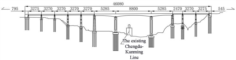
This paper focuses on the research object of a certain rigid frame bridge’s rotating construction beam section. This beam section consists of a 5×32 m + (52 m + 88 m + 52 m) continuous beam + 1×24 m + 2×32 m hole span layout, as shown in Figure 1. Considering factors such as construction difficulty, impact on existing lines, and construction safety risks, the main span part adopts horizontal rotation construction. Rotation T-frames are constructed at piers No. 6 and No. 7 on both sides of the existing railway line. After construction, horizontal rotation is performed, and closure sections are constructed using self-closing steel shells above the existing line, minimizing the impact on the existing railway. During the preparation stage of this rotation construction, under static wind loads, there may be significant effects on the safety and stability of the structure in both transverse and longitudinal directions. On one hand, during the preparation stage of the rotation construction, the stability of the superstructure mainly relies on the friction torque provided by the ball joint system to resist overturning moments caused by external wind loads. On the other hand, during the rotation process, due to the dynamic changes in the bridge’s superstructure, its stability is not only affected by wind loads but also influenced by factors such as unbalanced weight distribution.
Fig. 1Schematic diagram of the main beam part of the rotating structure (unit: m)
3. Stability calculation of a rigid bridge in the preparation stage of rotating construction
3.1. Frictional moment before turning
To verify the stability of a rigid frame bridge during the preparation stage of rotational construction, the friction torque before rotation was first calculated. Based on domestic construction data of similar rotating bridges, the static friction coefficient of the spherical hinge obtained from balancing and weighing tests typically ranges from 0.018 to 0.1, lower than the design value of 0.1 [7]; the measured static friction coefficient for this bridge was determined to be 0.04. For the analysis of general stability, static friction coefficients of 0.04, 0.05, 0.06, 0.07, 0.08, and 0.09 were adopted. With a total superstructure weight of 73500 kN, a spherical hinge radius of 8 m , and a cantilever length of 22 m , the friction torque before rotation was calculated as = 23520 kN⋅m when 0.04, with results for other coefficients summarized in Table 1.
Table 1Friction moment under different ball joint static friction coefficient (unit: kN m)
Static friction coefficient | 0.04 | 0.05 | 0.06 | 0.07 | 0.08 | 0.09 |
Friction moment | 23520 | 29400 | 35280 | 41160 | 47040 | 52920 |
3.2. Stability calculation of the transverse bridge
During the preparation stage of bridge rotation construction, the sole main support between the superstructure and substructure is the spherical hinge system, making the transverse stability significantly affected by wind loads. Based on the wind speed, wind pressure, and geometric characteristics of the bridge, the design wind speed was set to 25 m/s, the terrain category was classified as B, the conversion factor was taken as 1, and the air density was set to 1.25. The drag coefficient was obtained from Table 1 of the Wind Resistant Design Specification for Highway Bridges (JTG/T 3360-01-2018), and was herein taken as 1.4. Using the wind load calculation method specified in Eq. 1 of the aforementioned specification, the transverse wind-induced moment before rotation was calculated to be 14980 kN·m, and the transverse stability safety factor was subsequently determined using Eq. (1):
where, represents the bending moment caused by wind loads on the transverse direction before rotation, while represents the friction torque before rotation. Here, , where is the static friction coefficient, is the reaction force at the support, and is the eccentricity (lever arm) from the point of action of the friction force to the center of rotation. The product is approximately 238 kN·m. Based on the above calculations, the safety stability factor for the transverse direction of the superstructure before rotation is obtained, as shown in Table 2.
Table 2Lateral safety stability coefficient before rotation
Static friction coefficient | 0.04 | 0.05 | 0.06 | 0.07 | 0.08 | 0.09 |
Safety stability factor | 1.57 | 1.96 | 2.36 | 2.75 | 3.14 | 3.53 |
As shown in Table 2, the transverse safety stability coefficient increases significantly with the static friction coefficient, indicating that the friction moment at the ball joint is crucial for transverse stability [8]. When the friction coefficient ranges from 0.04 to 0.09, the coefficient meets design requirements, demonstrating adequate stability against wind loads before rotation.
3.3. Longitudinal bridge direction stability calculation
Although the longitudinal direction of the superstructure of a rigid frame bridge is less affected by wind loads, it is necessary to consider the unbalanced weight between the two cantilever segments. Ten scenarios of unbalanced weight () ranging from 0, 1 %, 2 %, 3 %, 4 %, 5 %, 6 %, 7 %, 8 %, and 9 % were considered for calculating the longitudinal stability of the rotating structure. First, the overturning moment caused by the unbalanced weight was calculated as , where is the total weight of the superstructure on one side of the rotation (here taken as 73500 kN), is the unbalanced weight, and is the cantilever length (here taken as 22 m). The unbalanced moment generated by the unbalanced weight in the longitudinal direction of the superstructure is shown in Table 3.
Table 3Unbalanced moment generated by longitudinal bridge to unbalanced weight (unit: kN m)
The imbalance is heavy | unbalanced moments | The imbalance is heavy | unbalanced moments |
0 | 0 | 5 ‰ | 8085 |
1 ‰ | 1617 | 6 ‰ | 9702 |
2 ‰ | 3234 | 7 ‰ | 11319 |
3 ‰ | 4851 | 8 ‰ | 12936 |
4 ‰ | 6468 | 9 ‰ | 14553 |
Next, considering the safety stability factor of the longitudinal bridge, it is necessary to consider the wind load and unbalanced weight of the longitudinal bridge at the same time, and the safety stability factor of the longitudinal bridge direction is obtained from Eq. (2):
For the rigid frame bridge under site wind conditions, a friction coefficient of 0.04-0.09 and unbalanced weight within 0-9 ‰ ensure sufficient stability before rotation. Longitudinal and transverse safety factors increase with friction coefficient [9]. However, longitudinal stability decreases as unbalanced weight increases, showing its dominant influence on rotational stability [9]. Thus, strict control and detailed recording of concrete volume at cantilever ends are essential to limit unbalanced weight during construction.
4. Stability calculation of a simply constructed bridge during the rotation construction
4.1. Frictional moment during rotation
The stability of a rigid frame bridge during rotation is analyzed by calculating the frictional moment of the rotating system. For piers 6 and 7, the ratio of starting to sliding traction force is 0.56 and 0.53, respectively. Dynamic friction coefficients of 0.01-0.035 are used to evaluate superstructure stability. The total rotating mass, spherical radius 8 m, and ball hinge friction moment (11760 kN·m) are considered. Friction moments under different coefficients are shown in Table 5. Results indicate that increasing the dynamic friction coefficient significantly enhances anti-overturning capacity, improving resistance to transverse wind loads during rotation.
To evaluate the stability of a rigid frame bridge during its rotation construction phase, the friction torque was first calculated. The friction coefficient for smooth surfaces is taken as 0.01, for rough surfaces as 0.02, and for very rough surfaces as 0.04. Based on this, six different scenarios were considered, ranging from smooth to rough contact surfaces, using dynamic friction coefficients of 0.01, 0.015, 0.02, 0.025, 0.03, and 0.035 to calculate the safety stability of the superstructure during rotation. For a particular rigid frame bridge with a total mass of 7350 t and a spherical hinge radius of 8 m, when the dynamic friction coefficient 0.02, the friction torque of the spherical hinge was calculated to be 11760 kN⋅m. Similarly, the friction torques for other dynamic friction coefficients are shown in Table 4. It can be concluded that an increase in the dynamic friction coefficient significantly enhances the anti-overturning capacity of the bridge during rotation, effectively mitigating the effects of lateral wind loads.
Table 4Friction moment under different ball hinge friction coefficients (unit: kN m)
Coefficient of kinetic friction | 0.01 | 0.015 | 0.02 | 0.025 | 0.03 | 0.035 |
Ball hinge friction torque | 5880 | 8820 | 11760 | 14700 | 17640 | 20580 |
4.2. Stability calculation of the transverse direction
In the process of rotating construction, similarly, the bending moment generated by the transverse 2958 kN⋅m, bridge static wind load is calculated based on the wind load code, and the transverse bridge safety stability coefficient is calculated by Eq. (3):
The safety stability coefficient in the transverse direction is calculated according to the above formula, as shown in Table 5.
Table 5Safety stability factor of the transverse bridge during rotation.
Coefficient of kinetic friction | 0.01 | 0.015 | 0.02 | 0.025 | 0.03 | 0.035 |
Safety stability factor | 1.99 | 2.98 | 3.98 | 4.97 | 5.96 | 6.96 |
As shown in Table 6, the safety stability coefficient of the bridge rotating structure increases correspondingly as the dynamic friction coefficient rises from 0.01 to 0.035. Under all tested dynamic friction coefficients, the safety stability coefficients meet design requirements, demonstrating high reliability of the bridge during rotation. This indicates that the superstructure of the bridge maintains adequate safety stability under lateral wind loads during rotation construction [10].
4.3. Stability calculation of longitudinal bridge
Finally, considering the combined effects of wind loads and unbalanced moments on the longitudinal stability of the rotating bridge during construction, six scenarios of unbalanced weight () were selected: 0, 1 %, 2 %, 3 %, 4 %, and 5 %. Similar to Section 3.3, the overturning moment caused by the unbalanced weight was first considered. Using the formula , the longitudinal unbalanced moments under the six scenarios of unbalanced weight were calculated, as shown in Table 6.
Table 6Longitudinal bridge unbalance moment generated by different counterweights (unit: kN m)
The imbalance is heavy | 0 ‰ | 1 ‰ | 2 ‰ | 3 ‰ | 4 ‰ | 5 ‰ |
Unbalanced moments | 0 | 1617 | 3234 | 4851 | 6468 | 8085 |
Next, considering the longitudinal safety stability coefficient under the combined effects of wind loads and unbalanced moments during bridge rotation, it was calculated using Eq. (4):
As shown in Table 7, the longitudinal safety stability coefficient during rotation is influenced by dynamic friction coefficient and unbalanced weight. Both coefficients increase with friction coefficient [11], while longitudinal stability decreases as unbalanced weight increases. Sufficient stability is achieved when friction coefficient > 0.015 or unbalanced weight ≤ 3 ‰. At 0.015 friction and 5 ‰ unbalance, the coefficient drops to 1.1, nearing the critical threshold – risking instability under dynamic effects.
Thus, unbalanced weight must be strictly controlled, ideally ≤ 4 ‰ via counterweights or construction adjustments. Increasing friction coefficient, especially by applying high-friction materials like modified epoxy resin on contact surfaces, significantly enhances stability. Controlling unbalance and enhancing friction are key to safe rotation.
Table 7Safety stability coefficient of longitudinal bridge during rotation
Safety stability coefficient of longitudinal bridge direction under different unbalanced weight rotations | |||||
0 ‰ | 1 ‰ | 2 ‰ | 3 ‰ | 4 ‰ | |
0.01 | 115.3 | 3.5 | 1.8 | 1.2 | 0.9 |
0.015 | 172.9 | 5.3 | 2.7 | 1.8 | 1.4 |
0.02 | 230.6 | 7.1 | 3.6 | 2.4 | 1.8 |
0.025 | 288.2 | 8.8 | 4.5 | 3.0 | 2.3 |
0.03 | 345.9 | 10.6 | 5.4 | 3.6 | 2.7 |
0.035 | 403.5 | 12.3 | 6.3 | 4.2 | 3.2 |
5. Conclusions
This study investigates the wind stability of a rigid frame bridge during rotation using theoretical and numerical analysis. A static gust wind load model was applied to evaluate transverse and longitudinal wind effects, and safety stability coefficients were analyzed considering friction moments of the spherical hinge system. Key findings are:
1) Before rotation, the safety stability coefficient increases significantly with static friction coefficient (0.04-0.09), showing that friction torque is crucial for resisting lateral wind-induced overturning. With unbalanced weight controlled within 0-9 ‰, both transverse and longitudinal stability meet design requirements, though longitudinal stability decreases with increasing unbalanced weight, indicating its critical influence.
2) During rotation, higher dynamic friction enhances stability. Transverse stability is dominated by lateral wind, while longitudinal stability depends on both longitudinal wind and unbalanced weight. The bridge demonstrates sufficient wind resistance under various conditions.
3) Strict control of unbalanced weight – via counterweight adjustment or construction sequencing – and increased friction through high-friction interface materials are essential for safe rotation.
References
-
W. Li, “Research on dynamic stress-free configuration finite element and negative angle vertical rotation construction control of reinforced concrete arch bridges,” Dalian University of Technology, 2013.
-
M. Liu, Horizontal Rotation Construction Technology and Application of Bridges Spanning Existing Railway Lines. Beijing: Science Press, 2016.
-
B. Wu, J. Zhou, S. Li, J. Xin, H. Zhang, and X. Yang, “Combining active and passive wind tunnel tests to determine the aerodynamic admittances of a bridge girder,” Journal of Wind Engineering and Industrial Aerodynamics, Vol. 231, p. 105180, Dec. 2022, https://doi.org/10.1016/j.jweia.2022.105180
-
“Wind resistance design code for highway bridges (JTG/T3360-01-2018),” People's Communications Press, Beijing, Ministry of Transport, 2019.
-
B. Wu, J. Zhou, J. Xin, H. Zhang, and F. Wu, “A numerical-experimental framework to separate the effects of different turbulence components on the buffeting forces of bluff-body structures,” KSCE Journal of Civil Engineering, Vol. 27, No. 8, pp. 3386–3402, Aug. 2023, https://doi.org/10.1007/s12205-023-0675-y
-
H. Li, L. Zhang, B. Wu, Y. Yang, and Z. Xiao, “Investigation of the 2D aerodynamic admittances of a closed-box girder in sinusoidal flow field,” Journal of Civil Engineering, Vol. 26, No. 3, pp. 1267–1281, Mar. 2022, https://doi.org/10.1007/s12205-021-0610-z
-
C. Carlet, G. Gao, and W. Liu, “A secondary construction and a transformation on rotation symmetric functions, and their action on bent and semi-bent functions,” Journal of Combinatorial Theory, Series A, Vol. 127, pp. 161–175, Sep. 2014, https://doi.org/10.1016/j.jcta.2014.05.008
-
J. Zhou, N. Li, X. Zeng, and Y. Xu, “A generic construction of rotation symmetric bent functions,” Advances in Mathematics of Communications, Vol. 15, No. 4, pp. 721–736, Jan. 2021, https://doi.org/10.3934/amc.2020092
-
Y. Su, H.-W. Liu, and W. Pedrycz, “A method to construct fuzzy implications-rotation construction,” International Journal of Approximate Reasoning, Vol. 92, pp. 20–31, Jan. 2018, https://doi.org/10.1016/j.ijar.2017.10.003
-
J. Shao, M. Duan, W. Yang, and Y. Li, “Research on the critical technique of synchronous rotation construction with large angle for T-shape curve rigid frame bridge,” Scientific Reports, Vol. 12, No. 1, Jan. 2022, https://doi.org/10.1038/s41598-022-05403-8
-
H. Zhang and S. Su, “A new construction of rotation symmetric Boolean functions with optimal algebraic immunity and higher nonlinearity,” Discrete Applied Mathematics, Vol. 262, pp. 13–28, Jun. 2019, https://doi.org/10.1016/j.dam.2019.02.030
About this article

This work was supported by the Science and Technology Research Program of Chongqing Municipal Education Commission (Grant No. KJQN202404320).
The datasets generated during and/or analyzed during the current study are available from the corresponding author on reasonable request.
The authors declare that they have no conflict of interest.
