Abstract
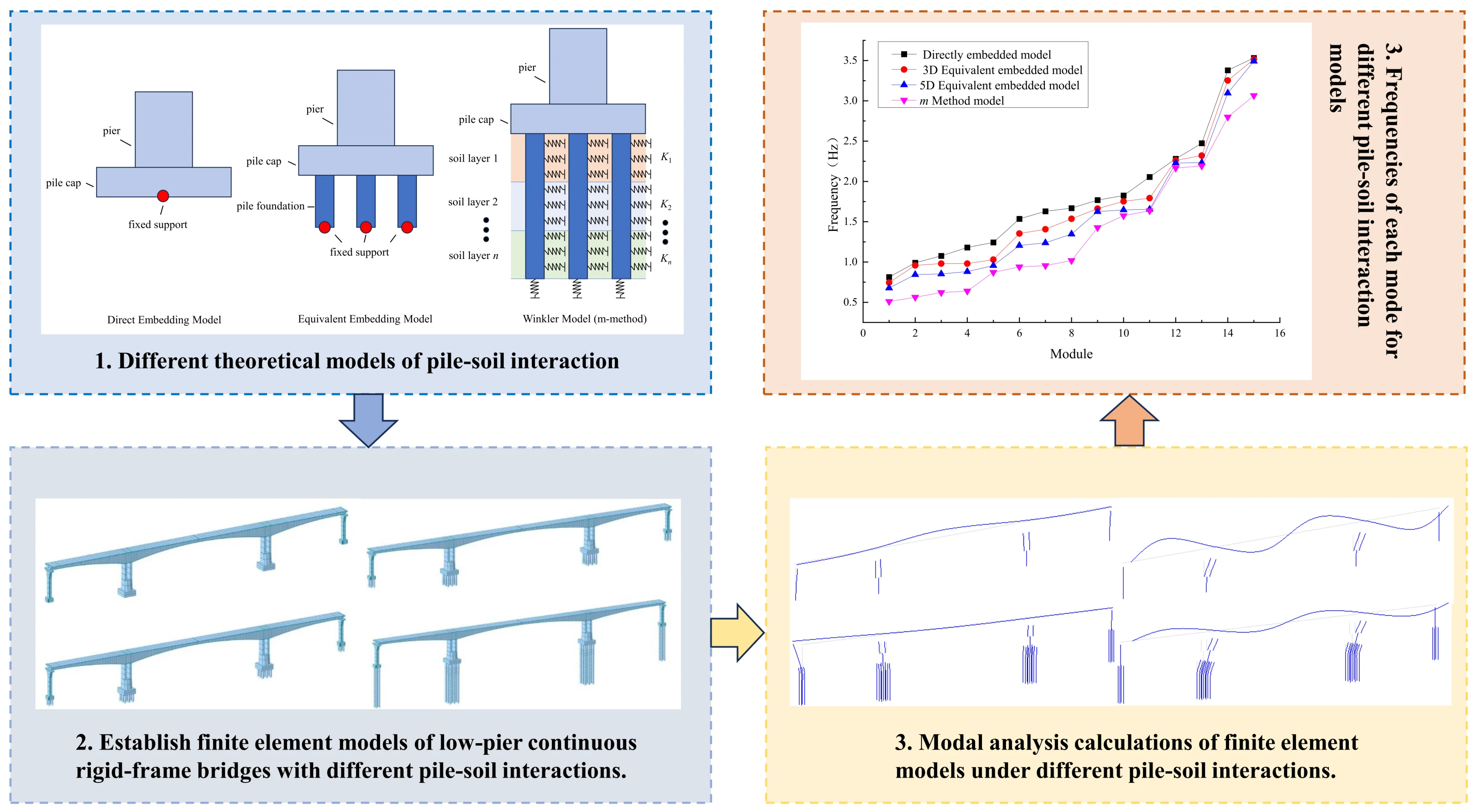
Taking a long-span continuous rigid-frame bridge with short piers as a case study, finite element models were developed in MIDAS Civil to account for both the presence and absence of pile-soil interaction. A comparative analysis was performed to evaluate the influence of pile-soil interaction on the dynamic characteristics of the structure. The results indicate that pile-soil interaction exerts a considerable influence on the vibration modes and natural frequencies of the bridge, with its impact being particularly significant for lower-order vibration mode frequencies. The directly embedded foundation model tends to overestimate the overall stiffness of the bridge, neglecting the flexibility effects of the pile group foundation. The equivalent embedded foundation approach can effectively simulate pile-soil interaction within a reasonable parameter range. However, for bridges with unfavorable geological conditions, large spans, and complex structural forms, it is recommended to adopt the m-method for pile group simulation to obtain accurate and realistic dynamic characteristic results.
Highlights
- Demonstrated that pile–soil interaction significantly affects vibration modes and natural frequencies of long-span continuous rigid-frame bridges with short piers, with the strongest impact on lower-order modes.
- Showed that neglecting pile–soil interaction can overestimate overall stiffness and natural frequencies, with frequency errors up to 84.38%.
- Verified that the equivalent embedded-foundation method effectively captures pile–soil effects within a reasonable parameter range; for unfavorable geology, large spans, or complex structures, the m-method for pile groups is recommended to improve dynamic analysis accuracy.
1. Introduction
Long-span continuous rigid-frame bridges have become one of the principal structural forms for modern long-span bridges due to their superior mechanical performance, strong spanning capabilities, and the seamless integration of economic efficiency with aesthetic appeal [1]. Traditional designs of continuous rigid-frame bridges typically utilize tall piers, where the inherent flexibility of the pier body significantly diminishes the rigid constraint effect of the pier top on the main girder. However, in specific contexts – such as municipal bridges and cross-lake projects – constraints related to route alignment and geological conditions often necessitate the adoption of short-pier continuous rigid-frame systems. The reduction in pier height leads to a substantial increase in the lateral stiffness of the pier body, which, in turn, results in a significant rise in the bending moment at the pier base and the foundation reaction forces. These effects may often prevent the structure from meeting strength criteria [2]. To address this issue, engineering practice commonly involves expanding the foundation scale. By leveraging the flexibility of pile group foundations, this approach effectively mitigates the adverse effects of internal force distribution within the structure. Existing studies have also shown that reducing pier height has a significant impact on the vibration characteristics of continuous rigid-frame bridge structures [3]. As long-span, short-pier continuous rigid-frame bridges continue to evolve rapidly, research into their dynamic characteristics is of considerable engineering significance, providing insights that can enhance both design and structural performance.
Currently, studies on the dynamic characteristics of long-span continuous rigid-frame bridges frequently employ the rigid foundation assumption (fixed base, FB), thereby neglecting the influence of pile-soil interaction (pile–soil interaction, PSI) [4]. However, accounting for pile-soil interaction can significantly alter the dynamic response of the structure, and in some cases, its impact is too substantial to disregard. Scholars such as Lü [5], Lou [6], and Yang [7] have conducted vibration table tests using model boxes, demonstrating that the PSI effect markedly influences the dynamic response of structures. Mylonakis et al. [8] found that considering pile-soil interaction results in the actual natural period of a structure being longer than theoretical predictions. An inaccurate estimation of the structural period may cause the structure’s natural period to coincide with the site’s characteristic period during earthquakes, potentially amplifying seismic effects. Similarly, Ceroni et al. [9] observed that pile-soil interaction not only increases the structural period but also enhances structural damping.
At present, there are relatively few studies on the influence of pile-soil interaction on the dynamic response of long-span continuous girder bridges. Given the flexible nature of group pile foundations, the impact of pile-soil interaction on the dynamic behavior of low-pier continuous rigid-frame bridges is even more pronounced.
In this study, a long-span, low-pier continuous rigid-frame bridge is selected as a case study to comparatively analyze the effects of considering and neglecting pile–soil interaction on the overall dynamic characteristics of the bridge. The investigation reveals the influence patterns of pile–soil interaction on the dynamic response of such bridges, thereby providing a theoretical foundation and engineering reference for further research on the dynamic characteristics of this bridge type.
2. Pile-soil interaction analysis model
In MIDAS Civil simulations, the most commonly employed pile–soil interaction models are the direct fixity method, the equivalent fixity method, and the m-method. Schematic diagrams of the different models are shown in Fig. 1.
Fig. 1Different pile-soil interaction analysis models
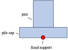
a) Direct embedding model
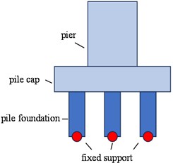
b) Equivalent embedding model
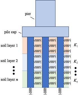
c) Winkler model (m-method)
2.1. Direct embedding model
The direct embedment model neglects the influence of both the pile foundation and subsoil on the structure by rigidly fixing the bottom of the bridge cap. In Midas Civil, this is simulated by fully constraining all degrees of freedom at the nodes located at the bottom of the bridge cap.
2.2. Equivalent embedding model
The equivalent embedding model neglects the influence of the subsoil by truncating the pile foundation at a specified depth below the ground surface or the maximum scour line, and rigidly fixing the pile base at this location. A critical aspect of this model is the determination of the fixity depth, which is commonly taken as three to five times the pile diameter. In MIDAS Civil, this is simulated by modeling the pile foundation as beam elements with lengths equal to three or five times the pile diameter, and fully constraining all degrees of freedom at the bottom of the pile foundation.
2.3. Winkler model (m-method)
In the Winkler model, the pile foundation is idealized as a continuous beam resting on an elastic foundation that conforms to the Winkler hypothesis. To represent the influence of the surrounding soil along the pile shaft, the horizontal resistance of the soil is simplified as a series of linear elastic springs. The stiffness of these equivalent soil springs can be determined using the m-method, as specified in relevant design codes. In MIDAS Civil, the pile foundation is modeled with beam elements corresponding to its actual design length, and the soil layers along the pile are divided so that each layer is associated with a node at its midpoint. Horizontal soil springs are then assigned to these pile nodes to simulate the lateral resistance provided by the soil.
The horizontal stiffness coefficient of each soil layer acting on the pile can be calculated based on the equivalent volume of soil surrounding the pile.
The horizontal stiffness coefficient of the first soil layer can be calculated as follows:
The horizontal stiffness coefficient of the second soil layer can be calculated as follows:
The horizontal stiffness coefficient of the nth soil layer can be calculated as follows:
where, is the design width of the pile; is the thickness of the th soil layer; is the proportional coefficient of the nth soil layer, which is obtained from experimental measurements. If no measurement data are available, the values in Table R-1 of Appendix R in Reference [10] can be adopted.
3. Project overview
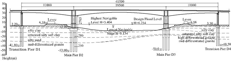
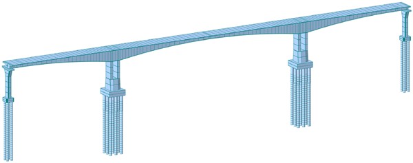
This study is based on a prestressed concrete continuous rigid-frame bridge with a span arrangement of 110 m + 195 m + 110 m, designed with separate decks for the two directions of traffic. The main girder is constructed with C55 concrete and adopts a single-cell, single-box cross-section. The top slab of the box girder is 16.4 meters wide, while the bottom slab is 8.4 meters wide. The girder height, bottom curve, and bottom slab thickness all vary according to a quadratic parabolic profile. At the top of the pier, the girder height is 11.5 meters, and at midspan, the girder height is 4.0 meters. The main pier foundation adopts bored cast-in-place piles with an integral cap. The pile foundation consists of 18 variable-diameter piles with diameters ranging from 2.8 m to 2.5 m and lengths of 42 to 45 meters. The transition piers use separated caps, each supported by four bored piles with a diameter of 2.0 meters and a length of 40 meters. At the bridge site, the average thickness of the silty clay layer is 10 meters, and the pier height is 27.05 meters, the ratio of the pier height to the main span is 1/7.2 and the piers are relatively low. The bridge layout is shown in Fig. 2.
Fig. 2Bridge layout (Elevation units: m; other units: cm)
4. Finite element model
To analyze the influence of pile–soil interaction on the dynamic characteristics of long-span continuous rigid-frame bridges, finite element models were developed using the MIDAS Civil software. The entire bridge was simulated using beam elements. A rigid connection was adopted between the main piers and the main girder, while a general connection reflecting the actual stiffness of spherical bearings was used between the transition piers and the main girder.
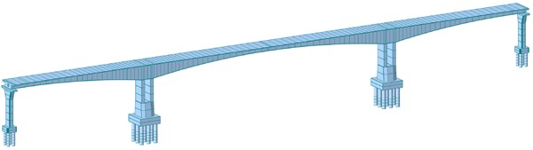
According to the boundary conditions of different pile-soil interaction simulation methods, four types of pile-soil effect analysis models were established using the various modeling approaches described in Section 2: direct embedment, 3D equivalent embedment, 5D equivalent embedment, and the m-method soil spring model, as shown in Fig. 3. The basic parameters for calculating the stiffness of the soil springs are presented in Table 1.
Table 1Basic parameters for calculating soil spring stiffness
Soil Type | Pile length (m) | Longitudinal (m) | Transverse (m) | |||
Transition Pier | Main Pier | Transition Pier | Main Pier | Transition Pier | Main Pier | |
Silty Clay | 10 | 4 | 2.06 | 2.41 (2.35) | 2.14 | 2.41 (2.35) |
Mud-Silty Clay | 10 | 10 | ||||
Silt | 8 | 11 | ||||
Mid-Weathered Granite | 12 | 20 | ||||
Note: The values in parentheses correspond to a variable diameter of 2.5 m | ||||||
Based on the basic parameters for calculating soil spring stiffness in Table 1, the stiffness of simulated springs at each node in the m-method soil spring model was calculated using Eqs. (1-3). A total of 649 simulated springs were set for the pile foundations of the entire bridge. The spring stiffness of typical nodes within each soil layer of the main pier D2 pile foundation is shown in Table 2.
Table 2Soil spring stiffness at typical nodes of main pier D2
Embedment depth (m) | Soil type | m value (kN/m4) | Node spring stiffness (kN/m) | |
SDx | SDy | |||
2 | Silty Clay | 7950 | 4.822×10⁴ | 4.618×10⁴ |
12 | Mud-Silty Clay | 9740 | 6.184×10⁵ | 5.976×10⁵ |
22 | Silt | 4950 | 8.707×10⁶ | 8.414×10⁶ |
35 | Mid-Weathered Granite | 99500 | 1.322×10⁷ | 1.277×10⁷ |
Note: The value of m is obtained from experimental measurements | ||||
Fig. 3Finite element model
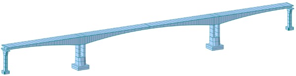
a) Direct embedding model
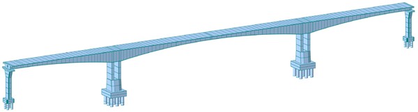
b) 3D equivalent embedding model
c) 5D equivalent embedding model
d) m-Method soil spring model
5. Dynamic characteristics analysis
In order to verify the influence of different pile–soil interaction simulation methods on the dynamic characteristics of the bridge structure, the dynamic characteristics of each model are analyzed.
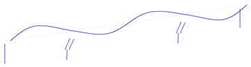
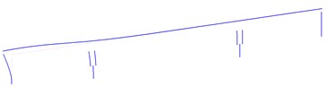
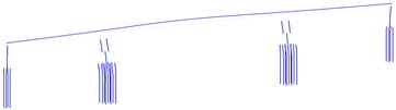
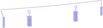
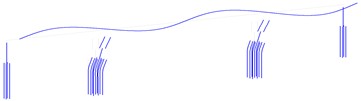
The vibration characteristics of a bridge structure mainly depend on its natural frequencies at various modes and its primary mode shapes [11]. Modal analysis was performed on each model using the eigenvalue analysis function in MIDAS Civil. The first four mode shapes of the fixed-base model, equivalent fixed-base model, and m-method soil spring model are shown in Figs. 4-6.
Analysis of Figs. 4-6 indicates that the first mode shapes of all models are consistent, each displaying a primary beam in symmetric lateral bending. In the fixed-base model, the second mode shape is characterized by symmetric vertical bending of the main beam, whereas in both the equivalent fixed-base and m-method soil spring models, the second mode shape is manifested as transverse displacement of transition pier D1. The third mode shape in the fixed-base and equivalent fixed-base models is antisymmetric vertical bending of the main beam, while in the m-method soil spring model, it is characterized by transverse displacement of transition pier D4. Significant differences are observed in the fourth mode shapes among the three models. Notably, the discrepancies between the equivalent fixed-base model and the m-method soil spring model are mainly reflected in the different orders in which the mode shapes appear, while the mode shapes of the fixed-base model deviate substantially from those of the other two models. In summary, except for the first mode shape, which is essentially the same across all bridge models established using different pile-soil interaction simulation methods, the order and frequency of the other mode shapes differ. This indicates that the pile-soil interaction has a significant impact on the variation trends of the structural mode shapes.
Fig. 4The first four mode shapes of the direct embedding model
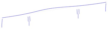
a) First mode shape (0.8131 Hz)

b) Second mode shape (0.9908 Hz)
c) Third mode shape (1.0762 Hz)
d) Fourth mode shape (1.1803 Hz)
Fig. 5The first four mode shapes of the 5D equivalent embedding model
a) First mode shape (0.6783 Hz)
b) Second mode shape (0.8436 Hz)
c) Third mode shape (0.8527 Hz)
d) Fourth mode shape (0.8812 Hz)
Fig. 6The first four mode shapes of the m-method soil spring model
a) First mode shape (0.5103 Hz)
b) Second mode shape (0.5626 Hz)
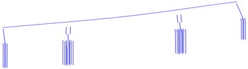
c) Third mode shape (0.6216 Hz)
d) Fourth mode shape (0.6402 Hz)
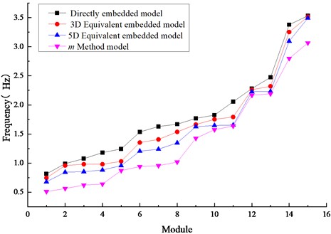
To investigate the influence of pile-soil interaction on the natural frequencies of the structure, the first 15 frequencies of each model were extracted, as shown in Fig. 7.
As shown in Fig. 7, there are significant differences in the frequencies at each mode among the four models. The fixed-base model yields the highest frequencies, followed by the equivalent fixed-base model, in which the frequencies at each mode decrease with increasing equivalent foundation depth. The m-method soil spring model produces the lowest frequencies. These results indicate that the fixed-base model overestimates the overall stiffness of the bridge and neglects the influence of pile foundation flexibility on the dynamic characteristics of the structure.
The largest frequency errors for the fixed-base model and the equivalent fixed-base model occur at the second and fourth mode shapes, respectively. Specifically, the frequency error for the fixed-base model is 84.38 %, while that for the equivalent fixed-base method (5D) is 49.95%. This indicates that the pile-soil interaction has the greatest impact on the second and fourth mode shapes.
A comparative analysis of the deviations between the frequencies of each mode in the fixed-base and equivalent fixed-base models and those in the m-method soil spring model shows that the average deviation of the first 15 frequencies in the fixed-base model is 43.53 %; for the equivalent fixed-base model with an equivalent length of 3D, the average deviation is 31.06 %; and for the equivalent fixed-base model with an equivalent length of 5D, the average deviation is 20.43 %. These results demonstrate that the equivalent fixed-base model exhibits smaller deviations from the m-method soil spring model, and that the deviation further decreases as the equivalent length increases. This indicates that the equivalent fixed-base model can effectively simulate pile–soil interaction. In practical modeling and analysis, the equivalent fixed-base model, with an appropriately selected equivalent length, can be conveniently employed.
Fig. 7Frequency calculation results of the four models
6. Conclusions
In this study, a long-span continuous rigid-frame bridge with short piers was selected as the research object. Finite element models considering and not considering pile–soil interaction were established, and the dynamic characteristics of each model were analyzed using MIDAS Civil. The influence of pile-soil interaction on the dynamic characteristics of long-span continuous rigid-frame bridges with short piers was investigated. The main conclusions are as follows:
1) Pile-soil interaction has a significant impact on the mode shapes and natural frequencies of long-span continuous rigid-frame bridges with short piers. Neglecting pile–soil interaction results in an overestimation of the calculated frequencies, with a maximum error of up to 84.38 %. This leads to an overestimation of the overall stiffness of the bridge and ignores the effect of pile foundation flexibility on the dynamic characteristics of the structure. Therefore, the influence of pile–soil interaction should be taken into account when performing dynamic analysis of long-span continuous rigid-frame bridges with short piers.
2) Pile-soil interaction has a considerable influence on the natural frequencies at all modes of the structure. For the long-span continuous rigid-frame bridge with short piers studied in this paper, pile-soil interaction has a more pronounced effect on the lower-order natural frequencies. The largest frequency errors for the fixed-base and equivalent fixed-base models occur at the second and fourth mode shapes, respectively, indicating that pile-soil interaction has the greatest impact on these modes.
3) The equivalent fixed-base method can effectively simulate pile–soil effects within a reasonable range of parameters and is relatively simple to model. However, the selection of the equivalent embedment depth requires comparative analysis. For bridges with poor geological conditions, large spans, and complex structural forms, it is recommended to use the m-method to simulate the group pile effect in order to obtain accurate and realistic results for the structural dynamic characteristics.
References
-
W. Qian, Q. Liang, W. Ningbo, and H. Dong Yang, “Dynamic impact coefficient of high pier large-span continuous rigid frame bridge,” (in Chinese), Journal of Vibration and Shock, Vol. 44, No. 7, pp. 209–216, 2025, https://doi.org/10.13465/j.cnki.jvs.2025.07.024
-
X. Lihai, X. Guangqing, and C. Xilong, “Research on construction monitoring technology for large-span short pier continuous rigid frame bridge,” (in Chinese), China Concrete, Vol. 3, pp. 54–59, 2024.
-
J. Llu and K. Wu, “Analysis of vertical vibrationcharacteristics of long span continuousrigid frame bridge consideringfoundation-pier-beam,” (in Chinese), Journal of Changsha University of Science and Technology (Natural Science), Vol. 13, No. 1, pp. 34–42.
-
D. Huihui, H. Jintao, and F. Guangming, “Consideration of the effect of pile-soil interaction on the dynamic response of double-column self-centering rocking bents under seismic action,” (in Chinese), China Journal of Highway and Transport, pp. 1–17, 2024.
-
L. Xilin et al., “Shaking table testing of dynamic soil-structure interaction system. Earthquake Engineering and Engineering Dynamics,” (in Chinese), Earthquake Engineering and Engineering Dynamics, Vol. 20, No. 4, pp. 20–29, 2000, https://doi.org/10.13197/j.eeev.2000.04.004
-
L. Menglin et al., “Shaking table model test of soil-pile-steel structure interaction system,” Earthquake Engineering and Engineering Dynamics, Vol. 29, No. 7, pp. 763–768, 2006, https://doi.org/10.13197/j.eeev.2006.05.037
-
J. Yang, Z. Lu, and P. Li, “Large-scale shaking table test on tall buildings with viscous dampers considering pile-soil-structure interaction,” Engineering Structures, Vol. 220, p. 110960, Oct. 2020, https://doi.org/10.1016/j.engstruct.2020.110960
-
G. Mylonakis and G. Gazetas, “Seismic soil-structure interaction: beneficial or detrimental?,” Journal of Earthquake Engineering, Vol. 4, No. 3, pp. 277–301, Apr. 2008, https://doi.org/10.1080/13632460009350372
-
F. Ceroni, S. Sica, M. Rosaria Pecce, and A. Garofano, “Evaluation of the natural vibration frequencies of a historical masonry building accounting for SSI,” Soil Dynamics and Earthquake Engineering, Vol. 64, pp. 95–101, Sep. 2014, https://doi.org/10.1016/j.soildyn.2014.05.003
-
“Specifications for design of foundation of highway bridges and culverts,” (in Chinese), JTG3363-2019, Ministry of Transport of the People’s Republic of China, 2019.
-
W. Lei, L. Wang, H. Shu, X. Liu, Y. Liu, and K. Chen, “Analysis of vehicle-bridge coupled vibration and driving comfort of a PC beam-steel box arch composite system for autonomous vehicles,” Buildings, Vol. 15, No. 8, p. 1385, Apr. 2025, https://doi.org/10.3390/buildings15081385
About this article

The authors have not disclosed any funding.
The datasets generated during and/or analyzed during the current study are available from the corresponding author on reasonable request.
The authors declare that they have no conflict of interest.
