Abstract
At present, few studies focus on variable-pitch fans for small-to-medium turbofan engines, with most relying on hydraulic actuation that fails to meet strict environmental and efficiency demands. This paper analyzes an electrically actuated lead-screw servo-motor-driven variable-pitch fan rotor: at 1×10⁷ N/m support stiffness, the first critical speed exceeds the operational range and pitch angle’s influence is negligible, peak unbalance response is 1.22×10⁻⁶ m linearly decreasing with pitch angle, and vibration analysis avoids resonance. Results confirm the electric pitch-change concept’s feasibility.
1. Introduction
In recent years, scholars at home and abroad have conducted very little research on the variable-pitch fan structure of small and medium-sized turbofan engines.
In turbomachinery fan rotor research, electric pitch change is key for environmental and efficiency needs. Variable-pitch fans outperform fixed-pitch ones – Sheard noted their better “stall tolerance”, laying a foundation for performance improvement [1]. Shah’s wind turbine research found variable-pitch mechanisms greatly boost power and torque, outperforming fixed-pitch significantly, highlighting wide applicability and a reference for turbomachinery fan rotor optimization [2]. Current fan rotor research still focuses on hydraulic actuation, whose limits fail modern turbomachinery demands. Kulkarni proposed full electric control for simplified hydraulic variable-pitch propellers, breaking hydraulic bottlenecks to shift to electric pitch change and indirectly revealing hydraulic drives’ poor flexibility and efficiency [3]. Wu Jiaxin proposed a comprehensive model linking electrical losses to system states to advance aviation electric pitch change and meet variable-pitch electric propulsion’s high-efficiency, high-performance thrust demands, highlighting electric actuation’s edge over hydraulic as hydraulic systems lack targeted optimization and cannot precisely match electrical losses to operating states [4].
Wu Jiaxin proposed a comprehensive model linking electrical losses to system states to advance aviation electric pitch change and meet variable-pitch electric propulsion’s high-efficiency, high-performance thrust demands, highlighting electric actuation’s edge over hydraulic as hydraulic systems lack targeted optimization and cannot precisely match electrical losses to operating states [5]. Song Junchen, Ouyang Huimin et al. built a magnetic bearing rotor 3D model in SolidWorks, imported it to Ansys Workbench for FEA, and focused on unbalanced forces’ rotor impact. Adjusting unbalanced force positions, they performed shafting unbalanced harmonic response analysis to verify modal accuracy. Their FEA methods provide key references for electrically actuated variable-pitch fan rotor modeling and analysis but exclude variable-pitch mechanisms [6]. Duan Ruke et al. developed a parametric FEA model to analyze micro-small turbojet rotor structural parameters’ dynamic impact and study parameter sensitivity on rotor dynamics. This improved turbomachinery rotor structure-dynamics analysis but excluded electric pitch change [7]. Chen Guangjiong et al. analyzed rotordynamics, calculated micro-small turbojet critical speeds, studied front and rear support harmonic responses under various positions, unbalance, phases and bearing damping, identified key assembly positions and proposed vibration reduction designs. This deepens turbomachinery rotordynamics application but still excludes electric pitch change [8]. Kang Xin studied nonlinear rotordynamics via finite element simulation, verifying feasibility and reliability with real-matching cases to support this study’s dynamic analysis method for electrically actuated variable-pitch fans [9]. Zhang Dongfeng analyzed gearbox high and low speed single shafts and rotor coupling vibration with finite element software, simulating rotational impact of single rotor unbalanced mass through harmonic response analysis. His method provides references for unbalance response studies of electrically actuated variable-pitch fan rotors [10].
2. Modeling
As shown in Table 2, static strength analysis was conducted on key components. All components have max stress below allowable levels, meeting safety factor requirements with reasonable displacements, confirming reliability under actual conditions.
Fig. 1Variable-pitch rotor structure of the adjustable rotor system
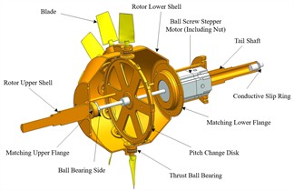
Fig. 2Finite element model of the rotor housing
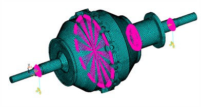
Rotor housing is 40Cr. For its FEA, the rotor assembly uses Solid186 elements, bearings as MASS21, and supports as COMBI214. Fig. 2 shows its FEA mesh with 241,321 nodes and 130,629 elements. In calculations, two bearing nodes are fully constrained except for rotation-axis displacement and angular displacement; two grounded nodes are fully constrained.
The element types used for the control group and all simplified models are detailed in Table 3, Considering the balance between computational accuracy and time efficiency, Simplified Model 3 is adopted as the preferred approach.
Table 1The positions of the centers of mass of the blades and the sine-based variable-pitch mechanism
Variable pitch angle (°) | Center of gravity (m) |
–20 | 3.4153×10⁻¹ |
–15 | 3.4059×10⁻¹ |
–10 | 3.3966×10⁻¹ |
–5 | 3.3872×10⁻¹ |
0 | 3.3777×10⁻¹ |
5 | 3.3682×10⁻¹ |
10 | 3.3588×10⁻¹ |
15 | 3.3495×10⁻¹ |
20 | 3.3401×10⁻¹ |
Table 2Table of Material Properties for Each Component
Part | Material | Density (kg/m3) | Young’s modulus (Pa) | Poisson’s ratio |
Blade | 7075 | 2810 | 7.00×10¹⁰ | 0.25 |
Crank and others | 40Cr | 7850 | 2.06×10¹¹ | 0.30 |
Guide rod | 40Cr | 7850 | 2.10×10¹¹ | 0.30 |
Bolt | Q235 | 7850 | 2.06×10¹¹ | 0.30 |
Table 3Table of element types for the control group and simplified models
Control group | Simplified model 1 | Simplified model 2 | Simplified model 3 | |
Variable pitch mechanism | Solid element | Lumped mass point | Lumped mass point | Lumped mass point |
Stepping motor | Solid element | Lumped mass point | Lumped mass point | Lumped mass point |
Lead screw | Solid element | Beam element | Beam element | Lumped mass point |
Guide rod | Solid element | Beam element | Lumped mass point | Lumped mass point |
Rotor-housing assembly | Solid element | Solid element | Solid element | Solid element |
3. Results and discussion
3.1. Analysis of the influence of variable pitch angle on critical speed
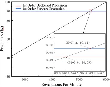
In the 0-3000 rpm range with 1×10⁶ N/m support stiffness and 3000-6000 rpm range with 1×10⁷ N/m support stiffness, critical speeds vary minimally with pitch angle, ranging from 2080 to 2082 rpm and 5402 to 5407 rpm respectively, confirming high rotor system stiffness. Support stiffness correlates positively with critical speed, jumping from approximately 2080 rpm to about 5400 rpm as stiffness increases by an order of magnitude, which aligns with rotor dynamics laws. Campbell diagrams show 1st order forward precession frequency increases linearly with speed with a slope of 1 while backward precession frequency stabilizes, verifying model reliability.
Fig. 3Campbell diagram –1×10⁶ N/m
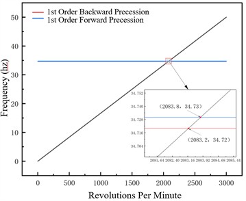
Fig. 4Campbell diagram –1×10⁷ N/m
3.2. Analysis of the influence of pitch angle on vibration response
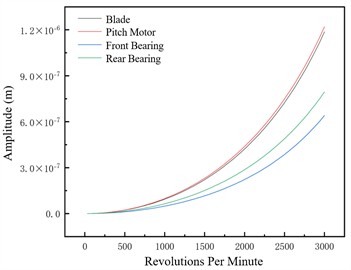
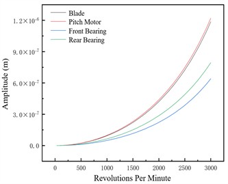
This section analyzes the effect of variable pitch angle on the rotor system’s dynamic characteristics under three support stiffness conditions. Blade amplitude rises significantly near critical speed but stays controllable across all pitch angles, indicating stable blade dynamic response without abnormal vibration from pitch angle adjustment; pitch motor amplitude follows the system’s overall trend, transitioning smoothly through critical speed with no significant response deviation across pitch angles, confirming the pitch control mechanism’s stability during adjustments. Key rotor-supporting front and rear bearings exhibit good amplitude responses, with amplitudes not exceeding the safety threshold at any pitch angle to ensure bearing support system reliability. Small amplitude variation with pitch angle is attributed to the system’s high overall stiffness, which resists deformation and thus minimizes large vibrations under disturbances like pitch angle adjustment.
Fig. 5Unbalance response of the unbalanced nodes at different pitch angles –1×10⁶ N/m
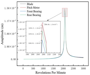
a) –15°
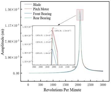
b) –10°
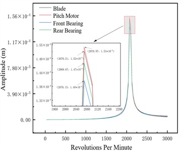
c) –5°

d) 5°

e) 10°
f) 15°
3.3. Unbalance responses of other nodes
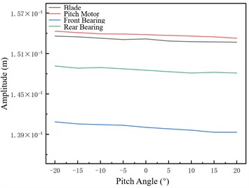
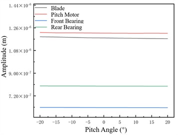
Fig. 7 shows unbalance responses of four axially distinct nodes to evaluate pitch angle’s rotor system impact. Amplitude varies approximately linearly; larger pitch angle reduces response by shortening unbalanced centrifugal force arm and weakening moment amplification, ensuring system compliance.
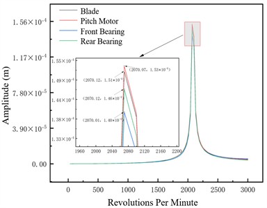
Fig. 6Unbalance response of the unbalanced nodes at different pitch angles –1×10⁷ N/m
a) –15°
b) –10°
Fig. 7Unbalance responses of four nodes at different variable pitch angles
a) 1×10⁶ N/m
b) 1×10⁷ N/m
4. Validation
To verify the electric-driven pitch control scheme’s feasibility, this chapter conducted experiments on pitch angle’s influence on critical speed and unbalance response under 1×10⁷ N/m support stiffness, with partial equipment shown in Fig. 10. Experimental equipment includes driving, testing, oil supply and auxiliary devices. The 55 kW three-phase synchronous motor with closed-loop speed control operates at 0 to 3600 rpm, with actual and input speed difference less than 1 rpm. Testing adopts Beijing Dongfang Institute’s DASP data acquisition and analysis system, consisting of software, hardware, acquisition cards and sensors.
Fig. 8Schematic diagram of the test rig
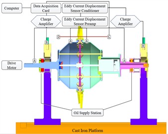
Fig. 9Test Rig – Photographed by Li Shuang at Rotor Dynamics Lab, Nanchang Hangkong University, Nanchang on 2025-08-16
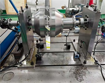
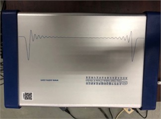
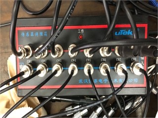
Fig. 10Partial experimental equipment. Photographed by Li Shuang at Rotor Dynamics Lab, Nanchang Hangkong University, Nanchang on 2025-08-16
a) Data acquisition card
b) Eddy current sensor conditioner
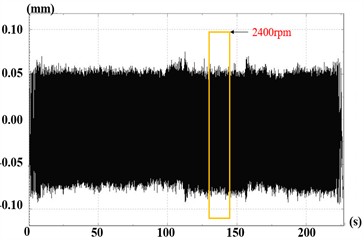
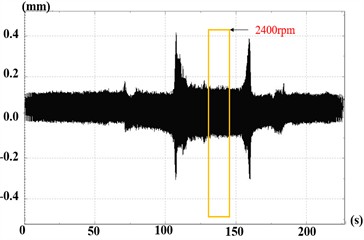
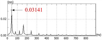
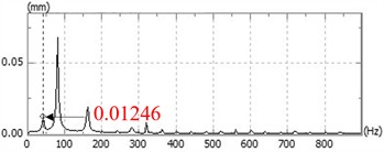
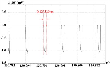
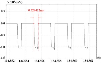
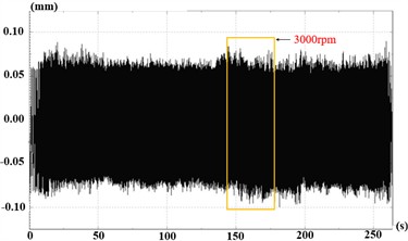
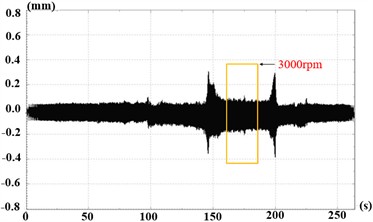
The experiment follows this sequence: prepare rotor test components, inspect all systems and test articles, debug data acquisition and testing systems, conduct stepwise speed-up tests to analyze pitch angle accuracy, perform tests at working speed, and finally decelerate. This section presents vibration response experiments of the adjustable rotor system at 2400 rpm and 3000 rpm, with measured data in Fig. 11 and Fig. 12 respectively.
Fig. 11Time-domain response and spectrum diagram at 2400 rpm
a) Point CH1
b) Point CH2
c) Point CH1
d) Point CH2
e) Before pitch angle change
f) After pitch angle change
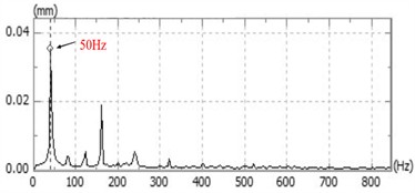
At 2400 rpm, the rotor reached maximum speed at 120 s, operated continuously for 30 s, then decelerated. CH1 peak amplitude is approximately ±8.0×10⁻² mm, CH2 around ±4.2×10⁻¹ mm. Waveforms show stable periodic vibrations without beat vibrations drift or divergence, indicating stable system operation with no friction instability or oil-film oscillation. A sharp peak appears at the 40 Hz fundamental frequency, with amplitudes between 1.2×10⁻² mm and 3.8×10⁻² mm, consistent with the designed speed.
Fig. 12Time-domain response and spectrum diagram at 3000 rpm
a) Point CH1
b) Point CH2
c) Point CH1
d) Point CH2
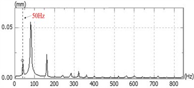
At 3000 rpm, the rotor reached maximum speed at 145 s, operated continuously for 30 s, then decelerated. CH1 peak amplitude is approximately ±8.0×10⁻² mm, CH2 about ±3.0×10⁻¹ mm. Waveforms are stably periodic without abnormalities, confirming no friction instability or oil whip. A sharp peak appears at the 50 Hz fundamental frequency, with amplitudes between 1.5×10⁻² mm and 4×10⁻² mm, matching the designed speed.
5. Conclusions
This paper takes the electric-driven adjustable fan rotor system as the research object, and details the influence law of the variable pitch angle on the dynamic characteristics of the adjustable fan rotor system through the calculation of critical speed and unbalance response. The conclusions are as follows:
1) The electric-driven variable pitch scheme is feasible: The analysis results under two types of support stiffness show that with the increase in the pitch angle, the variation law of the amplitude presents an approximately linear trend with a slight variation range. This indicates that the rotor system has sufficiently high overall stiffness, and the rotor is barely affected by the pitch angle during its operation.
2) Influence law of the variable pitch angle under different support stiffness conditions: When the support stiffness is 1×10⁶ N/m, a 1st-order critical speed occurs within 3000 rpm, and the unbalance response shows 1 peak, with the maximum amplitude lower than the material allowable value; when the support stiffness is 1×10⁷ N/m, the critical speed range is much higher than the operating speed range, and the system has no resonance risk.
3) Experimental Verification Summary: Vibration response tests of the adjustable rotor system at 2400 rpm and 3000 rpm both show stable periodic waveforms, with no obvious beat vibration, drift, or divergence. Combined with spectrum and time-domain diagrams, the system meets designed operating speed and motion characteristics, verifying the correctness of the pitch angle influence law analysis under 1×10⁷ N/m support stiffness as well as the effectiveness of the modeling method and analysis conclusions.
References
-
A. G. Sheard, C. Tortora, A. Corsini, and S. Bianchi, “The role of variable pitch in motion blades and variable rotational speed in an industrial fan stall,” Proceedings of the Institution of Mechanical Engineers, Part A: Journal of Power and Energy, Vol. 228, No. 3, pp. 272–284, Dec. 2013, https://doi.org/10.1177/0957650913516308
-
O. R. Shah, M. A. Jamal, T. I. Khan, and U. W. Qazi, “Experimental and numerical evaluation of performance of a variable pitch vertical-axis wind turbine,” Journal of Energy Resources Technology, Vol. 144, No. 6, Jun. 2022, https://doi.org/10.1115/1.4051896
-
P. K. Kulkarni, “Variable pitch propeller with electrical control,” Transactions of the Institute of Marine Engineers, Indian Division Supplement, No. n 28, pp. 1–5, 1969.
-
J. Wu, Y. Li, J. Hu, C. Liu, and M. Zhao, “A comprehensive model of variable pitch electric propulsion unit for optimal-power thrust control,” IEEE Transactions on Aerospace and Electronic Systems, Vol. 60, No. 3, pp. 3121–3131, Jun. 2024, https://doi.org/10.1109/taes.2024.3358263
-
N. N. He and H. Zhang, “The rotor dynamic analysis and optimization in turbocharger,” Applied Mechanics and Materials, Vol. 226-228, pp. 651–655, Nov. 2012, https://doi.org/10.4028/www.scientific.net/amm.226-228.651
-
J. C. Song, H. M. Ouyang, and G. M. Zhang, “Study on rotor dynamics of flywheel with magnetic suspension bearing based on finite element analysis,” Journal of Mechanical Strength, Vol. 37, No. 3, pp. 403–407, 2015, https://doi.org/10.16579/j.issn.1001.9669.2015.03.021
-
R. K. Duan, J. X. He, and M. Y. Li, “Study on sensitivity of rotor dynamic parameters based on finite element model,” Journal of Projectiles, Rockets, Missiles and Guidance, pp. 1–7, Aug. 2025.
-
G. J. Chen, Y. J. Zeng, and C. M. Pu, “Rotor dynamics analysis of micro turbojet engine,” Mechanical Engineer, No. 12, pp. 109–112, 2024.
-
X. Kang, “Research on finite element simulation method for nonlinear rotor dynamics,” Huazhong University of Science and Technology, 2015.
-
D. F. Zhang, “Study on rotor dynamic characteristics of gearbox in gear-increased centrifugal compressor,” Ningxia University, 2023.
About this article

The authors have not disclosed any funding.
The datasets generated during and/or analyzed during the current study are available from the corresponding author on reasonable request.
The authors declare that they have no conflict of interest.
