Abstract
Aimed at the vibration of whole aero-engine, a coupled dynamic model of rotor-ball bearing-stator of aero-engine is built. By means of the lumped mass method, taking into account the nonlinear rub-impact, bearing failure force and deformation of the casing, the dynamic equation of the system containing typical rub-impact is derived. The response of the system under different conditions is obtained by using the fourth order Runge-Kutta numerical integration algorithm. By adopting the finite element analysis software ANSYS, the finite element model of the rotor shaft is established and the first six-order natural frequencies of the rotor system are acquired. Taking advantage of the parameters of the signal in time domain and frequency domain, frequency characteristics are extracted as the fault features. The single-point rubbing experiment is carried out in the test rig, and the working speed is higher than the first critical speed, so the rotor shaft is flexible rotor. By the methods of spectrum and cepstrum analysis, the rub-impact characteristics of the casing vibration acceleration time series data are analyzed. The results show that the casing vibration acceleration has obvious impact characteristics; the impact frequency is equal to the product of rotating frequency and number of the blades; the impact frequency component and its multiple-frequencies are demonstrated in the frequency spectrum; the strength of impact is modulated by the rotating frequency, so that there are families of side bands on impact frequency and both sides of frequency doubling, and the interval of sideband equals the rotating frequency. The frequency components of the rotating frequency and its frequency doubling are clearly shown in the cepstrum. By comparing the simulation and experiment, the rubbing characteristics found out in this paper has enough accuracy.
1. Introduction
In rotating machinery, with the purpose of achieving the energy efficiency targets, it has been widely used to narrow the gap existing between the rotor and stator. However, the smaller the gap of the rotary machine is, the greater the likelihood of rub-impact occurs. The rub-impact has long been identified as one of the most typical fault in the rotor system, which can result in catastrophic consequences and short service life.
Due to the complexity of the rubbing fault, some studies on the rubbing experiments and rubbing dynamics mechanism have been carried out, which show some strong non-linear phenomena and characteristics caused by rub-impact, including waveform frustum, the frequency multiplication, difference frequency and chaos, and theoretical analysis have been verified by experiments in many literatures [1-9].
Sinou [10] researches the non-linear dynamic characteristics of a flexible rotor excited due to unbalance force and supported by ball bearings, detecting that the nth Fourier components are important when the rotor passes through the 1/n sub-critical resonances and critical speeds. Zhang and Meng [11-15] conduct a variety of researches on the non-linear Micro-Electro Mechanical Systems (MEMS), such as stability, bifurcation and chaos. Meanwhile, a set number of specific researches on the effects of several non-linear variables to rotor systems are also carried out.
The influences of different system variables on the rub-impact forces and transient responses under rub-impact status are analyzed in detail [16]. Zhang et al. [17] illustrate the rub-impact due to the geometric asymmetry existing between the rotor and the stator, and the grazing phenomenon of the single point rubbing is also discussed.
Ahmad [18] illustrates the influence of different system variables on the rotor dynamics, including stiffness, damping, acceleration of rotor, support structure asymmetry, thermal effects and disk flexibility etc.
Chen et al. [19] provide an overview of the studies on the kinetic characteristics of whole aero-engine systems in recent years which includes the dynamics research of the rub-impact of the rotor-casing system. Zhang et al. [20] consider the nonlinear restoring force of ball bearing, a novel fault diagnosis strategy based on rotor dynamics and computational intelligence is proposed.
Nevertheless, as for the aero-engine, the major differences of rubbing fault come from the following three aspects: (1) the casing thickness is about 1-2 mm (typical thin-walled structure) and its stiffness is also much smaller; (2) the rubbing fault mainly occurs between the rotor and the casing; (3) Under normal circumstances, only vibration acceleration on casing can be collected, and it is relatively hard to acquire vibration displacement.
All of the aforementioned characteristics are rarely taken into account in the existing experimental and theoretical studies, so they almost can’t be directly used to aero-engine rub-impact diagnosis. Thus, it is very important and essential to research the characteristics and laws of casing vibration acceleration time series data for the precise diagnosis of rotor’s radial rubbing faults of aero-engine.
The main contribution of this work is summarized as follows: (1) by dint of waveforms, time-frequency spectrums, orbit trails, phase plane portrait and Poincare maps, etc., many kinetic characteristics of radial rub-impact are stated. These obtained characteristics have an significant effect on the diagnostics of rotor’s radial rub-impacts; (2) a rotor experiment rig is used to conduct the single-point rubbing experiments; the casing vibration acceleration signals are measured, by means of the casing acceleration signals’ analysis, the characteristics and laws of blade-casing rub-impact are found out; (3) the results by analyzing numerical simulated response signal and practical experimental vibration signal demonstrate that the rub-impact model has enough accuracy.
2. Dynamical model of a rotating system
2.1. Coupled dynamic model of the system
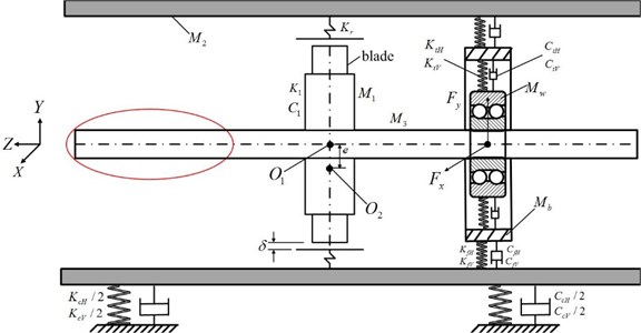
As the fault time series data are not easily obtained in many real equipments, especially for aero-engine, a dynamical model of whole rotor test rig which is built based on aero-engine and used to simulate a variety of typical faults is applied to generate fault data in this research. According to the real test rig in the laboratory, the test system is simplified as a rotor-bearing system, as shown in Fig. 1. The rotor system is composed of one disk with mass unbalance and one rotor supported by double row angular contact ball bearing which has a relatively large stiffness, in order to simulate the fan support way in the aero-engine. The motor drives the rotor system by using a plum coupling located at the right end, and the rub-impact is simulated at the disk.
The system modeling is completed by using 5 equivalent lumped mass elements, and , and denotes the masses of disk (including blades), stator and shaft, respectively; and are the corresponding lumped masses of bearing outer ring and bearing pedestal; , , , , , and represents the damping efficient; , , , , , , and denotes the stiffness factor. In these variables, the subscript represents the horizontal direction and the subscript indicates the vertical direction. For example, and represent the horizontal and vertical elastic support stiffness between the double row angular contact ball bearing and the bearing pedestal. Meanwhile, the blades are connected on the disk to simulate the real situation. According to the test rig, the part circled by the red line can be used to simulate the compressor of aero-engine in the model.
Fig. 1The rotor-ball bearing-stator coupling model
2.2. Rub-impact model
It is supposed that the heating effect caused by friction can be neglected. Based on the test rig, the stiffness is greater than the rigidity of the casing. Therefore, it can be assumed that the deformation just occurs on the casing. In contrast with the entire rotation period, the rub-impact time is so short that the contact occurring in the rotor and stator can be regarded as elastic impact. The torque effect is ignored when rub-impact model is established, and assuming that the rotating speed of rotor remains unchanged under rub-impact status. Under aforementioned suppositions, the physical model of the rotor radial rub-impact fault and the schematic diagram rotor impact are shown in Fig. 2.
When the rub-impact occurs between the rotor and stator, taking into account the transverse vibration of the rotor system, the differential equation governing the dynamical motion of the system based on barycenter motion theorem can be obtained as follows:
where denotes the radial displacement of the rotor relative to the casing, and , denote the horizontal and vertical displacement of the rotor, respectively; represents the masses of rotor (including disk and shaft); denotes the stiffness of the rotor,, and and are the stiffness components of the rotor in the horizontal and vertical directions, respectively; denotes the rotating speed of the rotor; and are the unbalance force components of the disk in and directions of rub-impact force; denotes the unbalanced direction angle; denotes the functional radial stiffness coefficient of stator; represents the radial damping ratio of the casing; denotes the imbalance; represents the rotor radius; ; denotes the tangential friction force under rub-impact status; value is expressed as follows:
Fig. 2Schematic diagram of radical rub-impact between the rotor and stator
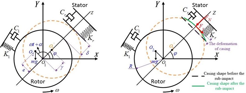
Supposing that the radical deformation of the casing meets the linear rule and the friction relationship when the rub-impact occurs between the rotor and casing conforms to the Coulomb friction law, which is still one of the most widely accepted models to describe the friction phenomenon. Let represents the friction factor, and the normal and tangential forces , due to rub-impact can be listed as follows:
It can be seen from these Eqs. (1)-(3), the physical model basically reflects the direct effect of rub-impact fault between the rotor and the casing. Note that the effect of addition torque caused by rub-impact on the rotor rotation is fully considered in the Eq. (1).
Non-dimensional transformation of Eq. (1) contributes to speeding up convergence and improving the stability of the solution. The non-dimensional parameters are defined as:
Let , and Eq. (1) could be further expressed in the simplified dimensionless form:
Without rubbing against the casing, is relatively small and can be neglected, and the governing equation of motion can be rewritten as:
Based on the equation solution theory, steady-state periodic solution is adopted to determine the solution of Eq. (5) and it could be assumed by the following form:
The stiffness components of rotor in horizontal and vertical are approximately equal, that is to say, (1). Under the condition, then Eq. (7) is substituted to the governing Eq. (6). The phase angle and the amplitude of the Eq. (6) can be obtained by:
2.3. Analysis of dynamic characteristics of the rotor system
The model of rotor system is composed of several parts: the main shaft, the disk and the related support structure such as bearings. Frankly speaking, because of the nonlinear complex characteristics caused by the interaction of different parts, it is quite difficult to build a model containing all the elements, such as the nonlinear oil film force from the bearing. Hence, it is necessary to do some simplification for the model.
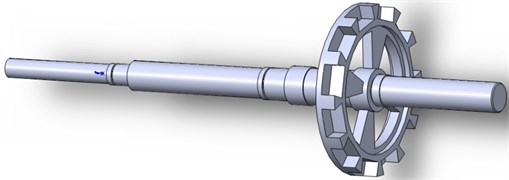
Based on the structure and the size of the rotor in the test rig, the solid model is set up by adopting 3D Design Software named Solidworks, as shown in Fig. 3. The large commercial finite software ANSYS would be used to perform the finite element analysis. According to the actual boundary condition of the shaft, the constraints of the double row angular contact ball bearing are imposed on the corresponding position of the shaft. The 3D geometry model is meshed and the FEM model is obtained, as shown in Fig. 4.
Fig. 3The 3D geometry model of the rotor
The motor is disposed at the left end of the rotor and drive the rotor through a coupling. The coupling also has a binding effect on the rotor radial and axial in turn when the motor torque is passed to the rotor system, so one zero axial displacement and two zero radial displacement constraints are applied on the left interface of the rotor.
Two types of elements in ANSYS software, Solid 185 and COMBIN14, are applied to mesh the 3D geometry model. The COMBIN14 element is used as the simplification of the bearings. Some of the calculation parameters, such as the material properties, the damp and the stiffness, are listed in Table 1.
Fig. 4The finite element model of the rotor
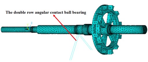
Fig. 5The modal map in the first six orders
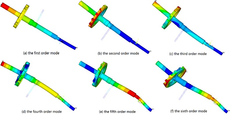
The solution can be obtained via the computer, the modal vibration modes in different orders (in this research we take the first six orders) and the corresponding frequencies are acquired (Table 2, Fig. 5).
On the basis Fig. 5, we can find that with the increase of vibration order, the frequency also become larger. Meanwhile, it can be clearly seen from the modal map that the sixth order’s vibration mode is quite fierce and complex. The first and the fifth order’s vibrations appear to be lateral vibrations. The others left show they include torsional vibration.
Table 1Parameters for calculation
Density | 7850 kg/m3 |
Poisson’s ratio | 0.269 |
Young’s modulus | 206 GPa |
Bearing stiffness | 7×10⁸ N/m |
Bearing damp | 2.5×10⁷ N.s/m |
Table 2Frequencies
Orders | Frequency (Hz) |
1 | 24.786 |
2 | 139.73 |
3 | 194.76 |
4 | 346.57 |
5 | 818.87 |
6 | 925.55 |
In order to extract fault features and reflect the operation condition of aero-engine as realistic as possible, combining with test rig equipment, the experimental rotating speed is set to 2100 rpm = 35 Hz. In the light of the Table 2 and the Fig. 5, the first order natural frequency of the rotor shaft is lower than the working speed, and the shaft is flexible rotor.
2.4. Analytical model of a flexible shaft supported by double row bearing
The vibration schematic diagram of a shaft supported by a double row angular contact ball bearing is shown in Fig. 6(a). As the outer raceway of double row angular contact ball bearing is a part of a sphere, the bearing can’t sustain any moment in any directions. Therefore, it is assumed that the system only has three translational degrees of freedom (, , ). According to the external load condition of the bearing, the imposed forces on the shaft can be described in the form of a load vector . Assuming the outer race of the bearing is fixed to the bearing housing (), the shaft is fixed rigidly with the inner race (). The rotational axis of the bearing is always collinear with the -axis. It is supposed that balls and races can be regarded as non-linear springs, and hence three relative displacements between the base and shaft are caused by these forces, which are expressed by means of a three-dimensional displacement vector in detail. In the diagram, the origin of the coordinate is defined by the outer raceway groove curvature center [21].
The dynamic behaviors of rolling elements, cage and inner race are demonstrated in Fig. 6(b). Spherical bearings are generally not suitable for these applications which operate in very high rotational speed, therefore centrifugal forces and gyroscopic moments on the rolling elements under the operating status are neglected [22, 23]. Assuming that the cage is rigid and massless, and thus the angular position of each rolling element relative to one another stays the same. Besides, provided that there is no gross slip on the ball-inner raceway contact surface, then the rotating speed of the rolling element set and cage can be formulated as:
Fig. 6Coordinate system and a shaft-double row bearing assembly: a) system forces and dynamic analysis, b) rolling speeds and load distribution
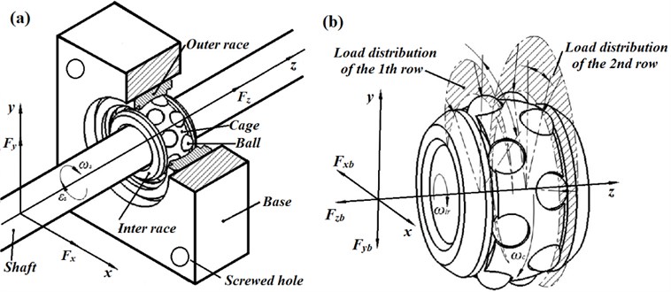
The load distribution of the rolling element is demonstrated in Fig. 6(b). In this research, the influence of friction is neglected. The contact force between raceway and ball is computed by using the classic Hertzian elastic contact deformation theory [22]. The Hertzian force just appears when contact deformation generates, so the force is defined to zero when raceway and ball separate. The total restoring force of all rolling elements can be presented as in terms of a load vector .
A commercial double row angular contact ball bearing whose properties are listed in Table 3 will be used in the calculation and experimental studies. These properties are either provided by the bearing manufacturer or determined from the dynamics, except for the Hertzian stiffness coefficient which could be found empirically [24].
Table 3Dynamic properties of the double row angular contact ball bearing used for calculation and experimental studies
Symbol | Value | Description |
12 | Number of rolling elements in one row | |
(N/mm1.5) | 654000 | Hertzian stiffness constant |
(mm) | 30 | Radius of the inner raceway groove curvature center (pitch radius) |
(mm) | 0.58 | Unloaded distance between inner and outer raceway centers curvature |
(mm) | 17.80 | Axial distance between the geometric center and bearing one row |
(deg) | 35 | Unloaded contact angle |
1.5 | Load-deflection exponent |
3. Responses of the system based on the dynamical model of the rotor system
It is apparent that Eq. (4) is a set of nonlinear differential equations. Therefore, the fourth Runge-Kutta method which is widely used to integrate the differential equation can then be applied for the solution to obtain the dynamic responses of the system in this paper. The key point in obtaining the reliable solution is to define proper time interval for the numerical integration. The parameters of the rotor system are listed in Table 1. The double row angular contact ball bearing is adopted in the system, and its parameters are shown in Table 3.
The dimensionless rotational period of the rotor is Vibration responses are first investigated for unbalance and then when rub-impact couples with unbalance. Steady state responses of the system are calculated for 150 periods with sufficiently small integration interval of 1/150th the time.
Fig. 7The time series, orbit map, phase plane portrait and spectral analysis at Ω= 1.39
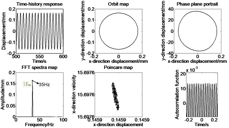
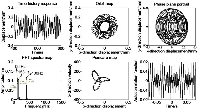
To ensure the stability of the data being used, the latter hundred-time series data of the integration are collected to conduct various kinds of analysis. In order to illustrate the nonlinear dynamic response of the rotor system, the dimensionless displacement of the rotor only without rub-impact fault in direction is displayed in Fig. 7 as well as the time series, orbit map, phase plane portrait, spectral analysis, Poincare map and autocorrelation function of -direction displacement at a rotating speed of 2100 rpm. The dimensionless speed ratio, , is served as a control variable, which represents the ratio of the rotating speed of the rotor and the inherent circular frequency of the rotor. The next step is to analyze the nonlinear dynamics response with rub-impact fault. The rotating speed is set to 24000 rpm, and the time series, orbit map, phase plane portrait, spectral analysis, Poincare map and autocorrelation function of -direction displacement are also obtained, as shown in Fig. 8. It may be noted that the vibration data of many complete cycles of rotor rotation is shown in the respective figures for all the cases discussed in the paper.
As shown in Fig. 7, rub-impact doesn’t occur and the corresponding non-linear characteristics doesn’t exist when the rotating speed is set to 2100 rpm. The imbalance characteristics are mainly exhibited under the simulation condition. It can be found from the Fig. 8 that the fundamental vibration (1×) and fractional frequency components are demonstrated in the spectrum diagram, as shown in Fig. 8. The rotor rubbing with the stator, involving nonlinear characteristics such as impacts and friction, is most often verified by the response of system [25].
Fig. 8The time series, orbit map, phase plane portrait and spectral analysis at Ω= 15.9
4. Analysis of rubbing faults’ characteristics based on the experiments
4.1. Introduction to the rotor test rig
Traditional rubbing experiments do not consider the thin-walled structure of the aero-engine and the disk-blade structure, therefore, the rubbing characteristics are not close to those of a practical aero-engine.
The test rig, which simply are composed of one stage fan blisk, bearing and rotor shaft assembly, is mainly used to simulate the unbalance and rubbing fault of aero-engine compressor parts. The structure design of the experiment is considerably improved. First, the shape and the material of the casing are basically consistent with those of the compressor casing. Second, the support structure is simplified as double row angular contact ball bearing to adjust the system’ dynamic characteristics. Third, the multistage compressor is simplified to a single-stage disk structure. Finally, 12 straight blades are adopted and lateral arranged evenly on the disk, which is mainly to reduce the influence of the air resistance, and to study the law of the mechanical structure. Besides, the top of the blade is designed arc-shaped, concentric with the casing, to facilitate the design of rubbing fault. Considering the safety of the installation of the blades, the blade-root portion in contact with the disk is designed trapezoidal, jammed by the centrifugal force of the rotating blades, to prevent the blades fly out. Three-dimensional structure of the blades and the disc are shown in Fig. 9; the acceleration sensors and rotor test rig are shown in Fig. 10.
Rubbing experiment simulates the situation that the rub-impact occurs between the blade and the casing. Hence, the nylon block is mounted on the casing. The single-point rubbing test is realized by adjusting the distance between the nylon block and casing, and using the blade length error existing in the process of the machining. Nylon block is arranged on the side of the horizontal acceleration sensor.
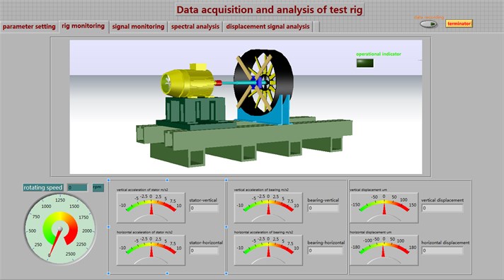
Based on LabVIEW software, the system has the parameter setting, real-time monitoring of the signal waveform, spectrum analysis, test rig monitoring and data logging functions. Data acquisition software - test rig monitoring interface is shown in Fig. 11.
Fig. 9Three-dimensional structure of the blades and the disc
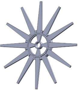
Fig. 10Rotor-disk-bearing-stator experimental rig
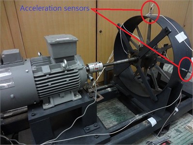
Fig. 11Data acquisition software – test rig monitoring interface
4.2. Characteristics analysis of casing acceleration signals under single-point rubbing
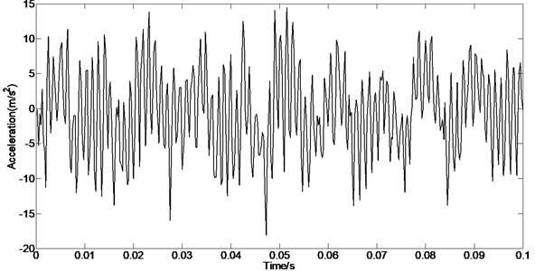
The testing data obtained from the horizontal acceleration sensor is selected. The corresponding rubbing position is the horizontal side; and the rotating speed is 2100 rpm = 35 Hz. Fig. 12 presents the time-frequency spectrum, time waveform and spectral analysis of the acceleration vibration signals collected from the casing, and Fig. 13 is the enlargement of time waveform in the Fig. 12. The enlargements of frequency spectrum plots are Figs. 14-15.
Because the rotor experiment rig is the shaft-disk-blade structure, when the rubbing occurs, and every blade hits the rubbing point in turn; this impact action circulates once when the rotor rotates a circle. Therefore, the impact frequency caused by rubbing is the frequency of blades passing the casing, and it equals the product of rotating frequency and the number of blades, therefore, in the frequency spectrum, there is the impact frequency and its multiple frequencies. Moreover, because of the excitation of unbalance force, the rotor produces the whiling motion whose frequency is equal to the rotating frequency, as a result, the strength of impact action of rubbing is modulated by rotating frequency. Thus, there is the obvious amplitude modulation characteristics in the frequency spectrum, namely there are many side bands on both sides of the rubbing frequency and its multiple frequencies. In the experiment data, the rotating speed is 2100 rpm, rotating frequency is 35 Hz, and the number of blades is 12, so the rubbing frequency is 420 Hz which is the product of the rotating frequency and the number of the blades. The rubbing frequency and its multiple frequencies are shown in Fig. 14, namely 354 Hz, 391 Hz, 425 Hz, 461 Hz, and 496 Hz. There are side band on both sides of them, and the side bands’ interval equals the rotating frequency which is 35 Hz, Fig. 14 is the enlargement near 420 Hz. It can be observed that the side bands near the 420 Hz, and the side bands’ interval equals the rotating frequency, and there are obvious quefrency components of the rotating frequency and its multiple frequencies, as shown in Fig. 16. In the low frequency segment of spectrum, the rotating frequency and its multiple frequencies components are shown in Fig. 15 [26].
Fig. 12Time-frequency spectrum, time waveform and spectral analysis of the acceleration signals
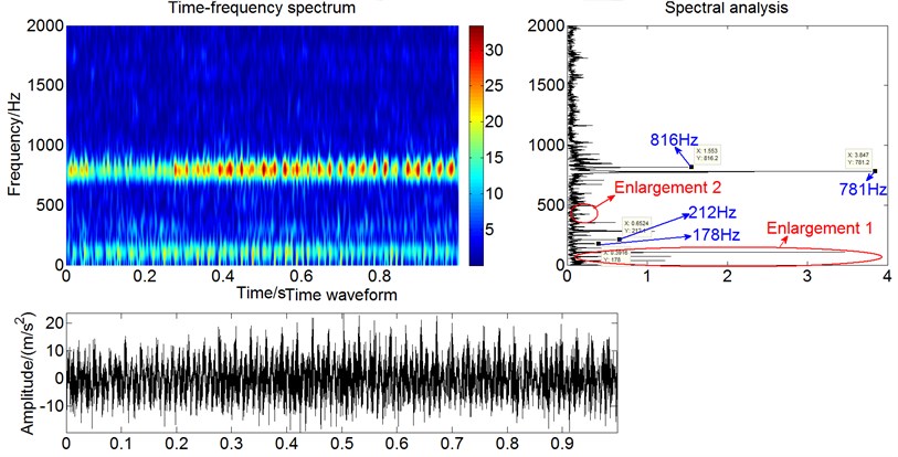
Fig. 13Waveform (enlargement of time waveform in the Fig. 12)
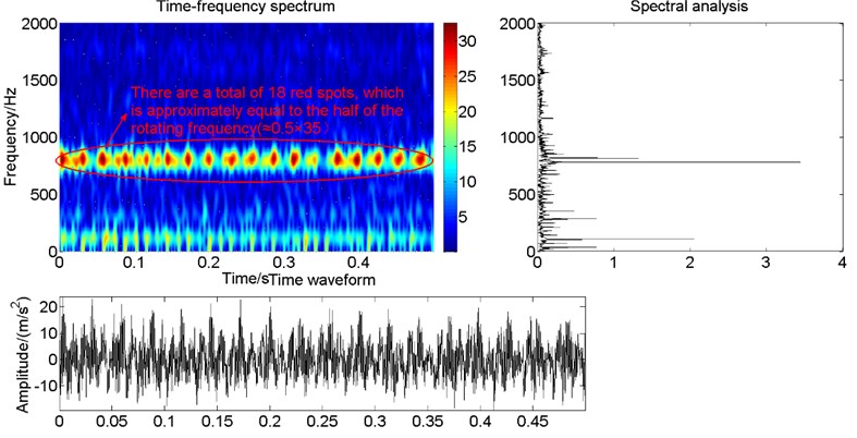
Since in the process of continuous sampling when rub-impact occurs, the intensity of rub-impact is greater and the rub-impact phenomenon is more obvious in the following time series data. Therefore, the second half segment of acceleration vibration time series data collected from the casing is analyzed again. The time-frequency spectrum, time waveform and spectral analysis are obtained as shown in Fig. 17. It can be found that there is a total of 18 red spots, which is approximately equal to the half of the rotating frequency (≈0.5×35 Hz). It can be seen from the spectral analysis that there exists the obvious frequency-modulated phenomenon. As aforementioned, the rub-impact characteristics, such as fractional frequency and frequency doubling, can be extracted effectively.
Fig. 14Spectrum analysis (enlargement 2 of spectral analysis in the Fig. 14)
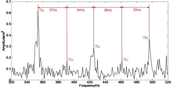
Fig. 15Spectrum analysis (enlargement 1 of spectral analysis in the Fig. 12)
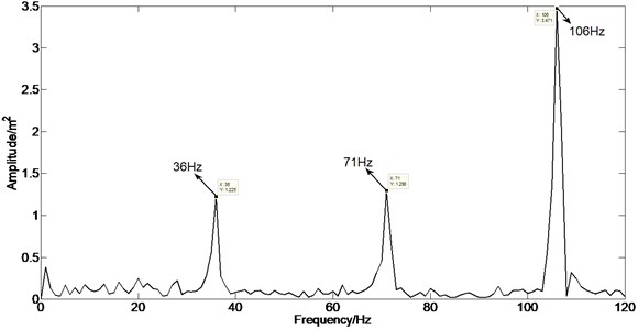
Fig. 16Cepstrum
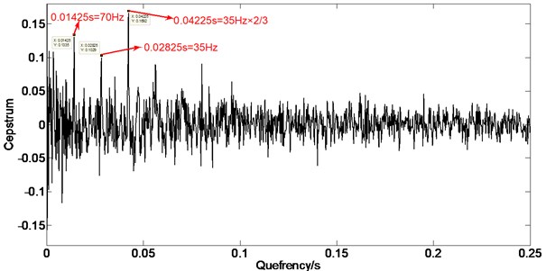
Fig. 17Time-frequency spectrum, time waveform and spectral analysis of the part acceleration signals
5. Conclusions
In this research, based on the Hertz contact theory and elastic collision theory, a new rub-impact model is built to investigate the rub-impact mechanism in rotating machinery. Meanwhile, the application of comprehensive spectral analysis and cepstrum analysis by means of acceleration signal collected from test rig is carried out to extract the rub-impact features. Finite element analysis of shaft is proposed to detect some dynamic characteristics by adopting the ANSYS software. It is noted that these approaches in yielding good results in rub-impact fault detection is effective.
1) It can be seen from the spectrum analysis of casing acceleration vibration signal that the multiple harmonic frequency components 2X and 3X, and fractional frequency component will become obvious when the rub-impact goes severe.
2) The casing acceleration vibration signals under rub-impact status have prominent cycle impact features; the impact frequency is in accordance with the product of rotating frequency and the number of blades; it may be noted from the frequency spectrum that there is the blades-passing frequency and its multiple frequencies.
3) In the low-frequency portion of the casing acceleration spectrum, more prominent rotating frequency and some multiple frequencies are present when the rub-impact occurs. For now, the aero-engine fault features mainly concentrate in the low-frequency segment, and the high frequency portion is generally neglected. Nevertheless, it is right the high frequency segment that contains the more significant features of aero-engine rub-impact fault.
4) By analyzing the acceleration vibration signals picked up from the casing, the accuracy and validity of rub-impact characteristics studied in the paper are confirmed.
5) In summary, it will provide a theoretical and engineering reference for fully understanding the rub-impact mechanism and diagnosis of a rotor system.
References
-
Muszynska A., Goldman P. Chaotic responses of unbalance rotor bearing stator systems with looseness or rubs. Chaos, Solitons Fractals, Vol. 5, Issue 9, 1995, p. 1683-1704.
-
Wen B. C., Wu X. H., Han Q. K. The Nonlinear Dynamics Theory and Experiments of Rotating Mechanism with Faults. Science Press, Beijing, 2004, p. 149-151, (in Chinese).
-
Chu F., Lu W. Experimental observation of nonlinear vibrations in a rub-impact rotor system. Journal of Sound and Vibration, Vol. 283, 2005, p. 621-643.
-
Gao Y. L., Li Y., Wang D. Y. Experimental investigation of rotor-to-casing rubbing fault. Aeroengine, Vol. 4, 2002, p. 16-21, (in Chinese).
-
Liu S. G., Hong J., Chen M. Numerical simulation of aero-engine blade-casing rubbing process. Aerospace Power, Vol. 26, Issue 6, 2011, p. 1282-1288.
-
Turner K., Adams M., Dunn M. Simulation of engine blade tip-rub induced vibration. Proceedings of GT2005, Ren-Tahoe, Nevada, USA, 2005.
-
Turner K., Dunn M., Padova M. Airfoil deflection characteristics during rub events. Journal of Turbomachinery, Vol. 134, 2012, p. 011018.
-
Chen G., Li C. G., Wang D. Y. Nonlinear dynamic analysis and experiment verification of rotor-ball bearings-support-stator coupling system for aero-engine with rubbing coupling faults. Journal of Engineering for Gas Turbines and Power, Vol. 132, 2010, p. 022501.
-
Cong Feiyun, Chen Jin, Dong Guangming, et al. Experimental validation of impact energy model for the rub-impact assessment in a rotor system. Mechanical Systems and Signal Processing, Vol. 25, 2011, p. 2549-2558.
-
Sinou J.-J. Non-linear dynamics and contacts of an unbalanced flexible rotor supported on ball bearings. Mechanism and Machine Theory, Vol. 44, Issue 9, 2009, p. 1713-1732.
-
Zhang W.-M., Meng G., Huang H., et al. Characteristics analysis and dynamic responses of micro-gas-lubricated journal bearings with a new slip model. Journal of Physics D: Applied Physics Vol. 41, Issue 15, 2008.
-
Zhang W. M., Meng G. Contact dynamics between the rotor and bearing hub in an electrostatic micromotor. Microsystem Technologies, Vol. 11, Issue 6, 2005, p. 438-443.
-
Meng G., Zhang W.-M., Huang H., et al. Micro-rotor dynamics for micro-electro-mechanical systems (MEMS). Chaos, Solitons and Fractals, Vol. 40, Issue 2, 2009, p. 538-562.
-
Zhang W.-M., Meng G., Zhou J.-B., et al. Slip model for the ultra-thin gas-lubricated slider bearings of an electrostatic micromotor in MEMS. Microsystem Technologies, Vol. 15, Issue 6, 2009, p. 953-961.
-
Zhang W.-M., Meng G., Chen D., et al. Nonlinear dynamics of a rub–impact micro-rotor system with scale-dependent friction model. Journal of Sound and Vibration, Vol. 309, Issues 3-5, 2008, p. 756-777.
-
Choy F. K., Padovan J. Non-linear transient analysis of rotor casing rub events. Journal of Sound and Vibration, Vol. 113, Issue 3, 1987, p. 529-545.
-
Zhang S., Lu Q., Wang Q. Analysis of rub–impact events for a rotor eccentric from the case. Journal of Vibration Engineering, Vol. 11, Issue 4, 1998, p. 492-496.
-
Ahmad S. Rotor casing contact phenomenon in rotor dynamics-literature survey. Journal of Vibration and Control, Vol. 16, 2010, p. 1369-1377.
-
Chen Y. S., Zhang H. B. Review and prospect on the research of dynamics of complete aero-engine systems. Acta Aeronautica et Astronautica Sinica, Vol. 32, 2011, p. 1371-1391.
-
Zhang Junhong, Ma Wenpeng, Lin Jiewei, et al. Fault diagnosis approach for rotating machinery based on dynamic model and computational intelligence. Measurement, Vol. 59, 2015, p. 73-87.
-
Zhuo Yaobin, Zhou Xiaojun, Yang Chenlong Dynamic analysis of double-row self-aligning ball bearings due to applied loads, internal clearance, surface waviness and number of balls. Journal of Sound and Vibration, Vol. 333, 2014, p. 6170-6189.
-
Harris T. A., Kotzalas M. N. Essential Concepts of Bearing Technology. CRC Press, Florida, 2006.
-
Royston T. J., Basdogan I. Vibration transmission through self-aligning (spherical) rolling element bearings: theory and experiment. Journal of Sound and Vibration, Vol. 215, Issue 5, 1998, p. 997-1014.
-
Harris T. A. Rolling Bearing Analysis. John Wiley and Sons, New York, 1991.
-
Junhong Zhang, Wenpeng Ma, Jiewei Lin, et al. Fault diagnosis approach for rotating machinery based on dynamic model and computational intelligence. Measurement, Vol. 59, 2015, p. 73-87.
-
Chen Guo Study on the recognition of aero-engine blade-casing rubbing fault based on the casing vibration acceleration. Measurement, Vol. 65, 2015, p. 71-80.
Cited by
About this article

The research is supported by the National Natural Science Foundations of China (No. 11572167). The authors are also grateful to the anonymous reviewers for their valuable comments. Meanwhile, deep gratitude should be forwarded to each participant or supporter in process of the troubleshooting which lasted nine months. In the process, not only have we learned how to do a better design, but also the teamwork spirit, the attitude of respect and reverence for technology, which is more important in research.
There is no conflict of interests in regard to publish of the paper.
