Abstract
In order to investigate the mechanism of a rotor system with unbalance and blade-casing rubbing coupling faults, the vibration and rub force in a rotor system resulting from unbalance and blade-casing rubbing coupling faults are simulated. At first, a dynamic model of 0-2-1 form rotor is established, and a blade-casing model, which considered blade number, clearance between the blade tip and stator, stiffness and size of the blade, is introduced to the rotor model. The characteristics of unbalance and blade-casing rubbing coupling faults are analyzed by waterfall plot, spectrum, time domain chart of vibration and rub force, and the effects of speed and clearance between the blade tip and stator. Secondly, a rotor system tester is established according to the model structure. The experimental test of rubbing is simulated by adjusting the Feeding Device to control the clearance between the blade and stator. After simulation and experimental results were compared, it was found that fraction frequencies and high integer frequencies were affected by a blade-casing rubbing fault, the clearance and speed had different influence on the dynamic characteristic of rotor system with blade-casing rubbing fault.
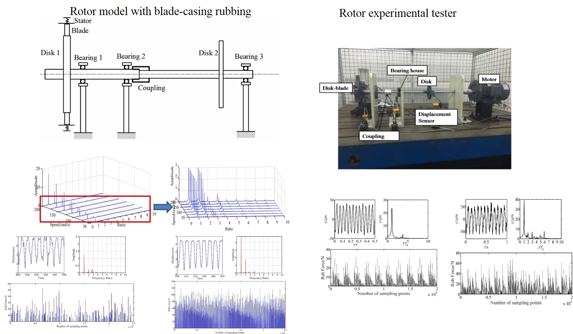
Highlights
- A model of blade-casing rub which considers the number, stiffness and size of blade is developed and applied on a “0-2-1” form rotor system with bearing and coupling.
- The variation law of the rubbing force and the spectrum characteristics of the rotor system with the change of the different conditions are studied.
- A rotor system tester is established according to the model configuration. The experimental results are demonstrated the correctness of the blade-casing rubbing model.
1. Introduction
The clearance between the blade tip and inner casing face has a great influence on compressor efficiency and fuel consumption of aero-engine. To improve the engine performance, one of the modern designs for such improvements aims at minimizing the blade-casing clearance [1]. However, with the decreasing clearance, the rotor and stator are at a high risk of collision which leads to rubbing faults. The rubbing has great effects on the vibration of the rotor system and has been recognized as the major causes of machine failure.
The blade-casing rubbing fault dynamic characteristic of the rotor system is one of the hot issues on rotor dynamics. Padovan [2] considered the transient analysis of rubbing problems, assumed the blade as a cantilever beam, built a blade-casing of a Jeffcott system which ignored the bearing support force, and studied the effects of blade parameters on rub force and blade stress. On the basis of this study, Jiang [3] deduced a model of normal rubbing force between the blade and casing with the consideration of Centrifugal Force and rotating speed. Lesaffre [4, 5] built an analytic model for calculating the blade dynamic nonlinear behavior associated with critical speeds during deceleration and acceleration processes, and used it for system stability analyses. Batailly [6] adopted an explicit time integration method to deal with blade-casing interaction on the basis of the Lagrange multiplier method and Coulomb friction law. Nan [7] deduced a blade model according to the cantilever beam assumption and analyzed the effects of stiffness, mass and excitation force on impact vibration of the system. Sinha [8] derived the basic dynamical equations for a rotating radial cantilever blade, and analyzing the transient response of displacement vibration and rub-force load; Almeida [9] studied the influence of friction on the blade response by time-frequency graph to show the spectrum of a contact force that followed exactly Signorini’s unilateral law with a single harmonic input; Ma [10] established a dynamic model of rotating shrouded blade considering the impact and analyzed the nonlinear and frequency characteristics of vibration and impact force, found that the impact force increased linearly with the increase of aerodynamic force amplitude. Legrand [11] proposed a three-dimensional investigation of structural contact interactions of turbo-machine, studied the displacement and contact force of nodes on blade, and analyzed the sensitivity to friction.
The above researches mostly focused on vibration features of the blade and casing, and few of them applied blade-casing rub models directly on the rotor system which considered other parts. Many scholars study blade casing rubbing faults by using an experimental test. Kennedy [12] performed the experimental test and simulation analysis on the rubbing between a steel blade tip and a flat copper plate which considered the temperature field and blade deformation. Wang B. [13] proposed an experimental study on rotating blade and static casing rubbing faults, the influences of the penetration depth and sliding speed on the rubbing faults were researched. Jiang [14] and Ahrens et al. [15] investigated the dynamics of rotor rubbing by experiment and measured the force and the duration during the contact process. Ma et al. [16] put up a blade-casing test rig with elastic casing, and analyzed the effects of casing materials on the normal force at lower speeds. Abdelrhman et al. [17] put up a multi-stage rotor system experiment test, which consisted of three rows of rotors each with different numbers of blades, and used casing vibration signals to extract the rubbing fault features. On the model simulation, Chen [18] developed an improved force model of blade-casing rubbing fault, simulated all kinds of rubbing, and analyzed their acceleration response, but the blade model only considered the casing stiffness, and ignored the blade characteristics. On the other hand, the rubbing fault always occurs along with another fault, and the unbalance is a common twinborn fault resulting in the rubbing fault. But these researches neglected the unbalance of the rotor which mostly led to the rubbing effect.
In this paper, a rotor-blade rubbing model which considered the rotor unbalance, blade number, stiffness and size is applied on a “0-2-1” form rotor system with bearing and coupling. The waterfall map, spectrogram, time domain chart are used to investigate the vibration characteristics of a rotor system with unbalance and blade-casing rubbing coupled faults and effects by the unbalance and blade-casing clearance. A “0-2-1” form rotor experimental test is built, and the vibration and rub force signals are collected and analyzed to verify the simulation results.
2. Model descriptions
2.1. Rotor system
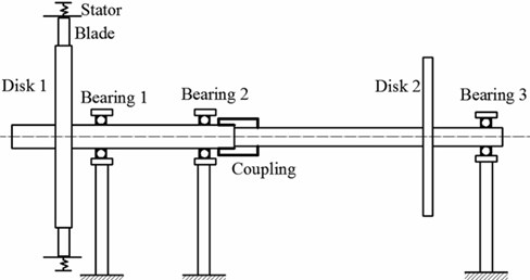
In order to study the nonlinear dynamic behavior under blade-casing fault, a mathematical model of a rotor-bearing system with rigid coupling is developed. The rotor model is developed as a two-shaft rotor connected by a gear coupling, with each shaft having a disk. The rotor is supported in the “0-2-1” form. The coupling is in the middle of the first and second supports, which are shown in Fig. 1.
Fig. 1Model of blade-rotor-bearing system
The motion equations of the above rotor system can be established as:
where and are the masses of Disk 1 and Disk 2, – are the masses of rotor points, and are viscous damping factors of disk and ball bearing, is the stiffness of rotor, and are blade-casing rub-impact force in the -axis and -axis directions, and are supported forces of ball bearing in the -axis and -axis directions, and are eccentricities of Disk 1 and Disk 2.
2.2. Ball bearing with elastohydrodynamic lubrication
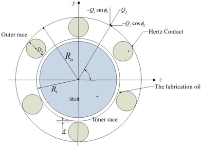
The sketch of the ball bearing is shown in Fig. 2. For the bearing model ignoring the effect of the lubrication oil, the load distribution of the bearing can be determined based on the Hertzian contact theory [19, 20]. Due to the operating condition of the rotor system, the centrifugal forces of the rolling elements should be considered. The model of ball bearing can be developed by following assumptions:
1. The outer rings are connected rigidly to the support and inner rings are fixed rigidly to the shaft.
2. The inner race, ball, and outer race move in the plane of bearing only.
3. The temperature of bearing is stable when the bearing is in operation.
According to the Harris’ work [21], the contact stiffness of a ball bearing can be calculated as follows:
where is the load of ball, is the contact deformation coefficient of the ball, and is the centrifugal force of the ball. The subscript “” refers to the ball number, and the superscripts “” and “” refer to the inner and outer races, respectively.
Regarding the point contact, the oil film thickness equation proposed by Hamrock and Dawson [20] is appropriate for the ball bearing:
where is a non-dimensional velocity, is a non-dimensional material parameter, is a non-dimensional load parameter, is the ellipticity of the rolling element, is the dynamic viscosity, is the linear velocity, is the equivalent Young’s modulus, is the Poisson’s ratio, and is the pressure-viscosity coefficient.
Fig. 2Schematic diagram of ball bearing
Then the oil film stiffness between the rolling element and the inner race can be calculated as:
The oil film stiffness between the rolling element and the outer race, , can be calculated in the same way. Thus, the total oil film stiffness of the bearing and rolling elements can be obtained:
Accordingly, the radial contact load of a rolling element can be calculated as:
Then the supporting forces of the ball bearing in the and directions are given as:
2.3. Rub-impact model
On the basis of Padova’s study [2], a rub model, which considered the parameters of blade and the relationship between rotor vibration and blade tip, was proposed. This model relies on the following assumptions:
1) The blade is assumed as a cantilever beam and fixed at the rotor mounting, the interaction between blades is neglected.
2) The bare casing is assumed to be rigid compared to the blade flexibility.
3) The connection structure between blade and rotor is ignored, they are assumed as a whole.
4) The Coulomb type of frictional relationship is used in blade and casing connection. The material removal is no longer in consideration.
Fig. 3Blade-casing rub model
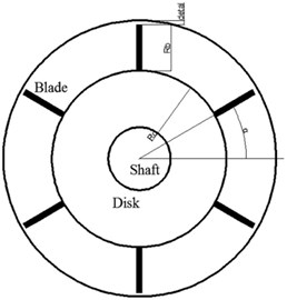
Assuming the , are the rotor vibrations in the in the and directions, the vibration of th blade tip can be calculated as:
where is the length of blade, is the radius of rotor, is the angle of the th blade, and the radial displacement of th blade tip can be calculated as:
According to the research of Padova [2], the Normal rubbing force of th blade can be as:
where is the Young’s modulus of blade, is the moment of inertia of the blade, is the length of the blade, is the radial displacement of th blade in the radial direction. is the flexural rigidity, in this paper, the blade is assumed to be rectangular.
Then the rub-impact forces on the rotor in the and directions are given as:
3. Experimental rotor test
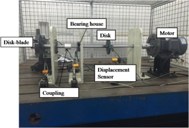
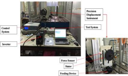
According to the structure of aero-engine, a test facility to simulate a compressor rotor system was built. Figure shows the overall test setup, test system and blade-casing rub simulation device. The system is simplified to a 0-2-1 support structure form. There are two supports between two disks and one support at the right side of the disk without blade. The left disk with blades which is disk 1 in Fig. 1 is to simulate the blade-casing rubbing faults. The rotor system was supported by three bearings, two shafts connected by coupling. To simulate the blade-casing rubbing, a feeding device was introduced. This device can adjust the clearance between stator and blade by the control system. Two force sensors mounted behind the stator are used to measure the rub force. The contact force is measured by using biaxial piezoelectric sensors (axial and tangential directions) located at the contact surface and on the mounting. The blades were mounted on the disk by rivet connection. The parameters of the experiment are shown in Table 1.
Fig. 4Rotor tester: a) tester structure, b) test system and feeding device of tester
a)
b)
4. Computation solutions of model and results discussion
4.1. Numerical method
The motion equations of rotor system are solved by the Runge-Kutta method. The time varying data corresponding to the first 100 periods generated by numerical integration are deliberately excluded in order to discard the transient solutions. The Waterfall maps, time-domain maps and spectrogram were used to analyze the blade-casing rubbing vibration characteristics in the rotor system.
4.2. Result and discussion
4.2.1. Blade-casing rubbing characteristics
In this section, the vibration of rotor system with blade-casing rub fault was analyzed. The simulation conditions were as follows: (1) the Young’s modulus of blade 2.09×10¹¹ Pa and the moment of inertia of the blade 6.75×10⁻⁹m4; (2) the clearance 10-5 m; (3) the number of blade 6; (4) the friction coefficient ; (5) the rotation speeds are 500 and 1000 rpm.
From Fig. 5, it can be found that the fundamental frequency is the maximum frequency at any speed, when the speed is 50 rad/s. It is found that the fundamental frequency amplitude is 1.624, and 2 × fundamental frequencies and some fraction frequencies also appear there. With the speed increasing, the amplitude of the fundamental frequency and 2 × fundamental frequencies have demonstrated a significant growth, the fundamental frequency increases to 16.49 at 200 rad/s and 2 × fundamental frequencies increase from 0.2824 to 6.601 in the same range. The fraction frequency disappears, and high frequencies such as 4 × fundamental frequency, 5 × fundamental frequency appear at the speed of 125 rad/s and increase with the speed gain.
Fig. 5Waterfall plot of blade-casing rub under different speed

Fig. 6Vibration response of blade-casing rub at 50 rad/s
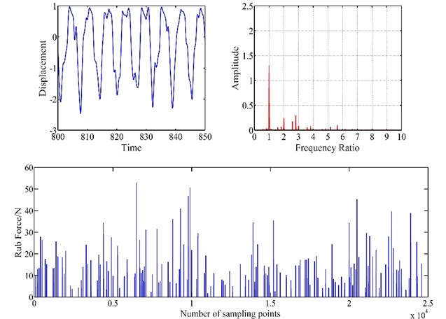
Fig. 7Vibration response of blade-casing rub at 100 rad/s
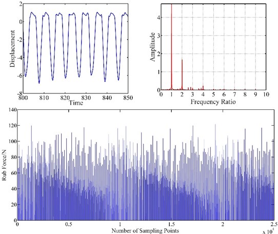
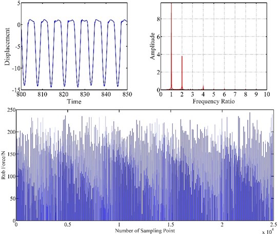
Figs. 6, 7, 8 show the vibration response of blade-casing rub system under different speeds. It can be found that the time domain of the system has several tip peak signals, it is also found that the fraction frequencies and integer frequencies appear on the spectrogram. The amplitude of time domain signal has changed under the effect of rubbing. The fraction frequency also appears. With the increase of speed, the amplitude of vibration has been greatly increased, the tip peak signal became weak, with the fundamental frequency and 2 × fundamental frequency have a great development on spectrogram. It is also found that the amplitude of rub force is increased with the development of speed, and the time interval between appeared rub force was shortened.
Fig. 8Vibration response of blade-casing rub at 150 rad/s
4.2.2. Effects of clearance
Fig. 9 is a waterfall plot of blade-casing rub under different clearances at 100 rad/s. According to this waterfall plot, the amplitude of fundamental frequency decreased from 5.132 to 1.496, the amplitude of 2 × fundamental frequency decreases from 1.838 to 0.2367, the amplitude of 4 × fundamental frequency decreases from 0.2649 to 0.021, while the amplitude of 3 × fundamental frequency changes in the range of 0.12 to 0.14, and 5 × fundamental frequency changes in the range of 0.05 to 0.06. Multiple frequencies and fraction frequencies also demonstrate some reduction. That means the blade casing rubbing levels have a great influence on the fundamental frequency and 2 × fundamental frequency and 4 × fundamental frequency, but affected a little on 3 × fundamental frequency and 5 × fundamental frequency.
Fig. 9Waterfall plot of blade-casing rub under different clearances

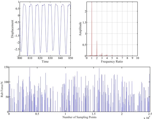
Figs. 10 and 11 show the vibration response of blade-casing rub system under different speeds. It is found that the clearance affects a little the amplitude of vibration on the time domain. However, the clearance affects obviously the fundamental frequency and 2 × fundamental frequency. The rub force decreases with increasing the clearance, and the interval time of rubbing also increases.
Fig. 10Vibration response of blade-casing rub at clearance 1.5e-6 m
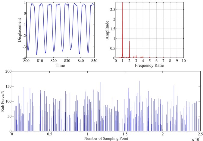
Fig. 11Vibration response of blade-casing rub at clearance 2e-6 m
5. Experimental results
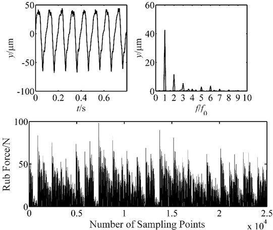
In the experiments, the blade-casing vibration data is collected at 500 rpm, 1000 rpm, 1500 rpm. The Feeding Device is adjusted to control the clearance between the blade and stator, and the displacement data and force signals are collected to analyze the accuracy of the blade-casing rub model.
Fig. 12Vibration response of blade-casing rub at 500 rpm
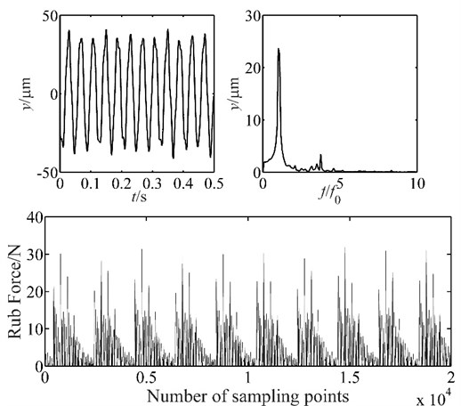
Fig. 13Vibration response of blade-casing rub at 1000 rpm
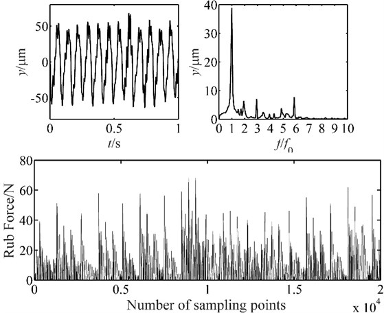
The experiment results are shown in Figs. 12, 13 and 14. It is found that the vibration of placement has several tip peaks, and some fraction frequencies appear at the speed of 500 rpm. When the speed increases, the amplitude of displacement vibration demonstrates a great growth, the amplitude of fundamental frequency also develops greatly, it grows from 24.2 μm to 43.2 μm. The rub force is developed, and no distribution rule is applied for the rub force at 1500 rpm. The results are agreed well with the characteristics of simulation results, and demonstrate the correctness of the blade-casing rub model.
Fig. 14Vibration response of blade-casing rub at 1500 rpm
6. Conclusions
A model of blade-casing rub which considers the number, stiffness and size of blade is developed and applied on a “0-2-1” form rotor system with bearing and coupling, the characteristics of vibration and rub force signal are studied under different rotor speeds and clearances.
The rotor model with blade-casing rubbing is used to simulate and calculate the response of displacement and rub force vibration under different conditions. Several results are obtained as follows: (1) The blade-casing rubbing affects the fundamental frequency, 2 × fundamental frequency, some fraction frequencies and high integer frequencies of the rotor system. (2) When the speed increases, the amplitude of the fundamental frequency and 2 × fundamental frequencies has a great development, and the fraction frequency begins disappearing, and the high integer frequency appears. When the clearance increases between blade and stator, the amplitude of the fundamental frequency, 2 × fundamental frequencies has great decreasing trend, fraction frequencies and high integer frequencies also decrease but not so obviously. (3) The rub force amplitude and distribution are also affected by the clearance and speed, the amplitude of rub force increases after the speed growth and clearance decrease, the time interval between rub force generations is shortened with the growth of speed and decrease of clearance.
A rotor system tester is established according to the model configuration. The blade-casing rubbing experiment is made by adjusting the Feeding Device to control the clearance between the blade and stator. The experimental results are agreed well with the simulation and demonstrate the correctness of the blade-casing rubbing model.
References
-
Ma H., Yin F., Guo Y., et al. A review on dynamic characteristics of blade-casing rubbing. Nonlinear Dynamics, Vol. 84, Issue 2, 2016, p. 437-472.
-
Padovan J., Choy F. K. Nonlinear dynamics of rotor/blade/casing rub interactions. Journal of Turbomachinery, Vol. 109, Issue 4, 1987, p. 527-534.
-
Jiang J., Ahrens J., Ulbrich H., et al. A contact model of a rotating rubbing blade. Proceedings of the 5th International Conference on Rotor Dynamics, 1998, p. 478-489.
-
Lesaffre N., Sinou J. J., Thouverez F. Model and stability analysis of a flexible bladed rotor. International Journal of Rotating Machinery, Vol. 2006, 2006, p. 63756.
-
Lesaffre N. Stabilité et Analyse Non-linéaire du Contact Rotor-Stator. Ph.D. Thesis, Ecole Centrale de Lyon, 2007.
-
Batailly, Legrand, Cartraud, et al. Assessment of reduced models for the detection of modal interaction through rotor stator contacts. Journal of Computational and Nonlinear Dynamics, Vol. 329, 2010, p. 5546-5562.
-
Nan G. F. Modeling and dynamic analysis of shrouded turbine blades in aero-engine. Journal of Aerospace Engineering, Vol. 29, 2016, p. 04015021.
-
Sinha S. K. Dynamic characteristics of a flexible bladed-rotor with Coulomb damping due to tip-rub. Journal of Sound and Vibration, Vol. 273, Issue 4, 2004, p. 875-919.
-
Almeida P., Gibert G., Thouverez F., et al. On some physical phenomena involved in blade-casing contact. Proceedings of the 9th International Conference on Structural Dynamics, 2014.
-
Ma H., Xie F., Nai H., et al. Vibration characteristics analysis of rotating shrouded blades with impacts. Journal of Sound and Vibration, Vol. 378, 2016, p. 92-108.
-
Legrand M., Batailly A., Magnain B., et al. Full three-dimensional investigation of structural contact interactions in turbomachines. Journal of Sound and Vibration, Vol. 331, Issue 11, 2012, p. 2578-2601.
-
Kennedy F. E. Single-pass rub phenomena – analysis and experiment. Journal of Lubrication Technology, Vol. 104, Issue 4, 1982, p. 582-588.
-
Wang B., Zheng J., Lu G. Rubbing contact between rotating blade and casing plate, part 1–experimental study. Key Engineering Materials, Vol. 233, 2003, p. 725-730.
-
Jiang J. Investigation of Friction in Blade, Casing Rub and Its Effect on Dynamics of a Rotor with Rubs. Shaker, 2001.
-
Ahrens J., Ulbrich H., Ahaus G. Measurement of contact forces during blade rubbing. IMECHE Conference Transactions, Vol. 2000, Issue 6, 1998, p. 259-268.
-
Ma H., Tai X., Han Q., et al. A revised model for rubbing between rotating blade and elastic casing. Journal of Sound and Vibration, Vol. 337, 2015, p. 301-320.
-
Abdelrhman A. M., Leong M. S., Hee L. M., et al. Application of wavelet analysis in blade faults diagnosis for multi-stages rotor system. Applied Mechanics and Materials, Vol. 393, 2013, p. 959-964.
-
Chen G. Simulation of casing vibration resulting from blade-casing rubbing and its verifications. Journal of Sound and Vibration, Vol. 361, 2016, p. 190-209.
-
Sarangi M., Majumdar B., Sekhar A. Stiffness and damping characteristics of lubricated ball bearings considering the surface roughness effect. Part 1: theoretical formulation. Proceedings of the Institution of Mechanical Engineers, Part J: Journal of Engineering Tribology, Vol. 218, Issue 6, 2004, p. 529-538.
-
Sarangi M., Majumdar B., Sekhar A. Stiffness and damping characteristics of lubricated ball bearings considering the surface roughness effect. Part 2: Numerical results and application. Proceedings of the Institution of Mechanical Engineers, Part J: Journal of Engineering Tribology, Vol. 218, Issue 6, 2004, p. 529-538.
-
Harris T. A. Rolling Bearing Analysis. John Wiley and Sons, 2001.
-
Jiang J. Determination of the global responses characteristics of a piecewise smooth dynamical system with contact. Nonlinear Dynamics, Vol. 57, 2009, p. 351-361.
-
Yuan Z., Chu F., Wang S., et al. Influence of rotor’s radial rub-impact on imbalance responses. Mechanism and Machine Theory, Vol. 42, Issue 12, 2007, p. 1663-1667.
-
Lu W., Chu F. Radial and torsional vibration characteristics of a rub rotor. Nonlinear Dynamics, Vol. 76, Issue 1, 2014, p. 529-549.
Cited by
About this article
This work was financially supported by the National Natural Fund (51501222) and the science and technology program of the Civil Aviation Bureau (MHRD20160106).
Ding Kunying designed the study, performed the research, analysed data, and wrote the paper. Wang Zhe designed research, performed research, analyzed data, and wrote the paper. Lu Xin helped develop the rotor model and developed the rotor test rig. Zhang Junhong did some of simulation works, and help to finish the fault experimental test. Ma Liang collected the simulation data and help on writing paper.
