Abstract
Wide-band electrical data contains abundant fault transient characteristics, but traditional transformers are difficult to accurately capture wide-band transient signals due to bandwidth limitations. To address this issue, this paper innovatively proposes a non-intrusive current measurement scheme based on an accurate time scale and develops a prototype device. A Tunnel Magnetoresistance (TMR) chip is used to detect the magnetic induction intensity generated by cable current, the ratio coefficient is derived from the spatial position of the high-voltage cable and the sensor, and data recording and real-time display are realized by a microprocessor. A low-noise adjustable gain sensing circuit and a transient signal wireless acquisition module are designed to improve the wide-band signal sensing capability; a mathematical model of the sensor installation position is established to achieve accurate reconstruction of the primary current. A validation platform is built to conduct measurement tests of Direct Current (DC), Industrial Frequency (IF), and transient processes, and a comparative experiment of ground fault current is carried out in a 110 kV high-voltage cable. The study identifies the key factors affecting the measurement accuracy of magnetoresistive sensors, and the experiments show that the measurement errors of DC and IF are controlled within 1 %, and the measurement errors of high-frequency signals do not exceed 3 %.This device adopts a combined power supply of solar cells and current transformer online power supply, which can provide up to 10 W of electrical power, with a lithium-ion polymer battery integrated inside as the energy storage module; the instrumentation op-amp is composed of three discrete operational amplifiers to meet the high bandwidth requirement for wide-band signal measurement.
1. Introduction
In recent years, a large number of nonlinear power electronic devices have been connected to the power grid, resulting in a significant increase in volatility and randomness. As a result, serious harmonics, three-phase imbalance and transient shock events have occurred in the power system, threatening the transmission and transformation equipment, and the safe and stable operation of the power system is facing great challenges [1].
Fully exploiting the wide-band transient signals of several kHz to MHz in high voltage cables can help to more accurately assess the state of the equipment and research more effective relay protection technology, so realizing the precise electrical quantity of high voltage cables and wide-band measurements is an important foundation to ensure the safe operation of the new power system [2].
For the current detection of high-voltage cables, the traditional measurement uses electromagnetic current transformers, but due to its parameters and other effects, it is difficult to transform high-frequency transient signals, in order to improve the bandwidth and reliability of the measurement, the development of optical current transformers, Rogowski coils and other electronic transformers [3]. However, there are still problems such as the need to change wiring, high cost, complex structure, and difficulty in taking into account AC and DC measurements [4], and it is impossible to adapt to the needs of the new power system for non-intrusive, small size, and accurate measurement of sensors [5]. With the development of smart grid technology, in recent years, relevant scholars have proposed a variety of intelligent sensing schemes based on MEMS combined with advanced sensing technology [6], Current sensors are rapidly developing towards miniaturization and miniaturization. Among the many MEMS current sensor technologies, tunneling magnetoresistance-TMR technology has attracted much attention due to its high sensitivity, low power consumption, and weak influence by parameters [7]. TMR is firstly used in power system to measure high frequency current signals, and it has been realized to measure the row current of cable intermediate joints through wired connection of data acquisition instrument [8].
With the development of new power systems, relevant scholars have focused on their miniaturization applications [9], The research has been carried out in the areas of very small current measurement, wide bandwidth characteristics and anti-interference analysis [10], [11], it promote the intelligent development of high-voltage cable current digital measurement [12]. However, most of the research on TMR measurement technology focuses on the optimization of the arrangement and other theoretical analysis of the experimental stage, the wide-band sampling data is difficult to be combined with the time and space of the actual power grid, and the use of its wide-band characteristics is relatively small, and can be used for transient protection analysis of high-voltage cables in the wide-band current wireless measurement device has not yet been put forward [13]. There is an urgent need to develop a non-intrusive wireless current measurement device with precise time scale to fully explore the wide-band transient signals inside the cables to provide strong data support for the condition assessment of high-voltage cables and the protection of transmission and cables [14]. And optical current transformers need to change wiring, Rogowski coils have high cost, complex structure, etc., and it is difficult to achieve AC/DC measurement at the same time, which cannot meet the needs of new power systems for non-intrusive, miniaturized, and high-precision sensors. The existing technology cannot effectively solve the problem of combining broadband sampling data with actual grid spatiotemporal information, especially in the measurement of broadband transient signals of high-voltage cables [15]. We Integrating TMR technology with wireless transmission systems enables accurate measurement of broadband transient signals over high-voltage cables through time synchronization and broadband performance optimization [16].
In order to realize the demand for multi-point holographic sensing of wide-band current signals of high-voltage cables, this paper proposes a non-invasive measurement method for wireless measurement of wide-band current of high-voltage cables and designs the principle prototype: firstly, the principle of current measurement based on the TMR effect is explained; then, for the demand of wide-band high-volume range measurement of high-voltage cables, a wide-band sensor module and a transient recording wireless measurement and transmission module are designed. Then the wide-band sensor module circuit and the transient recording wireless transmission module are designed for the unique wide-band and large-range measurement requirements in high-voltage cables, and the primary and secondary transformations and ratios are calculated according to the relative positions of the high-voltage cable connector and the TMR sensor; finally, the wide-band response of the TMR sensor is tested for the DC, AC, and transient signals, and the error is analyzed. The test results and 110kV high-voltage cable field experiments prove the feasibility of the proposed TMR effect-based wide-band current wireless measurement device. The device innovatively adopts a solar-current transformer hybrid power supply and a high-bandwidth instrumentation op-amp composed of discrete operational amplifiers, providing stable power supply and signal amplification guarantee for accurate wide-band current measurement, and further verifying the engineering practicality of the scheme.
In summary, existing technologies have collaborative gaps in wide-band adaptability, non-intrusive deployment, spatiotemporal synchronization, and engineering practicality. The innovations of this study are: 1) Integrating accurate time scale calibration with TMR sensing technology to realize wireless synchronous measurement of wide-band current in high-voltage cables for the first time, solving the problem that existing TMR devices are difficult to match the spatiotemporal information of actual power grids; 2) Innovatively designing a hybrid power supply system (including lithium polymer energy storage module) combining solar energy and current transformer, and a high-bandwidth instrumentation amplifier composed of discrete operational amplifiers, forming a “power supply-amplification-sensing” collaborative architecture to make up for the dual deficiencies of traditional measurement devices in power supply stability and bandwidth adaptability; 3) Constructing a mathematical model of sensor installation position, and combining with a wireless transmission module to realize accurate reconstruction of primary current under non-intrusive deployment, breaking through the limitations of existing wireless measurement devices in accuracy and transient signal capture capability.
2. TMR sensor measurement principle
2.1. Sensor characterization
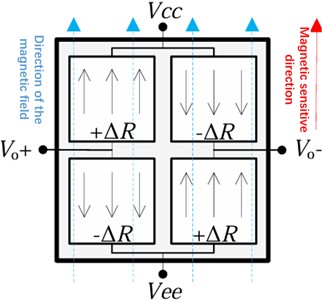
TMR sensor based on the TMR effect by the linear TMR sensing chip, TMR sensing chip is a measurement of the external magnetic field strength of the miniature sensing element, the use of MEMS technology to prepare the molding of the voltage output amplitude with the change of the external magnetic field strength changes in a certain range of excellent linearity. TMR sensing chip by the spin-valve structure of the multilayer membrane encapsulated by the chip using the four internal Inside the chip, 4 TMRs are used to form a Wheatstone bridge [12], As shown in Fig. 1, the single-axis TMR sensing chip has a fixed magnetic sensitivity direction, when the direction of the external magnetic field is the same as the magnetic sensitivity direction of the chip, the resistance of the bridge arm changes and outputs a positive voltage, and when the magnetic field direction is the opposite, it outputs a negative voltage.
Fig. 1Structure of the sensitive element of the TMR sensor chip
2.2. Current measurement principle analysis
When a current is passed through the cable under test, a rotating magnetic field is generated around it, the direction of which can be determined by the right-hand spiral rule. According to Biot-Savart’s Law, the magnetic induction at any point around the high-voltage cable can be calculated [13]. The magnitude of magnetic induction BP at point P in the space around a long straight high voltage cable as shown in Fig. 1 can be expressed as:
where is the permeability coefficient, it is H/m, is the current flowing through a high-voltage cable, is the distance between the point P and the line. We adopt single-axis TMR sensing chip close to the measured high-voltage cable, the distance between the TMR sensing chip and the measured high-voltage cable is much smaller than the distance to other phase lines, which avoids the interference between the lines.
To ensure the stability and consistency of magnetic field detection, the distance between the TMR chip and the measured cable is fixed at 2 mm in experimental deployment. Meanwhile, the direction of the magnetic field generated by the cable current is strictly controlled to be parallel to the magnetic sensitivity direction of the TMR chip, so as to avoid measurement errors caused by directional deviation.
Fig. 2Spatial magnetic induction intensity of current-carrying high-voltage cable

A constant excitation power supply with voltage is applied to the linear TMR sensor chip located at point P, and its output differential voltage signal is :
where is the sensitivity coefficient of the linear TMR sensing chip, and the unit is mV/[V(Am-1)-1], Indicates the output voltage value of the sensor per unit magnetic field strength and excitation voltage. is the strength of the magnetic field at point P; is the strength of the magnetization, and 0 in the absence of a ferromagnetic medium. can be expressed in the form shown in the following equation:
Unlike conventional transformers, Roche coils utilize the laws of electromagnetic induction for measurement [14]. Based on the current-induced magnetic field, the TMR sensor uses the TMR effect to measure the reverse current value of the magnetic field, and there is no complex winding in the structure, and it is less affected by the capacitance parameters of the stray inductor. Therefore, it can measure wide-band current signals from DC to several MHz, and in addition to the power frequency current measurement capability of conventional current transformers, it also has the ability to accurately measure small signals, DC components and high-frequency transient signals.
3. Design of wireless measuring device for wide band current in high voltage cables
The Wheatstone bridge in the TMR sensing chip is excited by the external power supply, induces the magnetic field strength parallel to the direction of magnetic sensitivity and outputs millivolt differential voltage signals, which are then processed by the multi-stage operational amplifiers in the sensor module and transmitted to the end wireless measurement transmission module, finally realizing the wireless measurement of wide-band current signals in the primary line. In order to ensure the measurement accuracy of the sensor and reduce the measurement error introduced by the external circuit, the following research and discussion will be carried out in the design of the power supply system, the design of the wide-band sensor module and the wireless measurement transmission module design.
3.1. Low noise power systems
Considering a variety of working conditions of the power supply, this paper proposes a wide-band current wireless measurement device using solar cells combined with current transformer online energy supply, can provide up to 10 W of energy power, energy storage module will be pooled in the internal integration of lithium-ion polymer batteries. The energy storage module collects the energy from the internal lithium-ion polymer battery, and then converts it into two stages: the first stage uses a switching power supply to convert the battery voltage into a positive and negative dual power supply; the second stage uses a linear power supply to regulate the output voltage, filter out the noise, and limit the ripple to a very small range, and then supply it to the operational amplifiers and the excitation power supply. The two levels of power supply and amplifier circuitry are enclosed in a shielded case independently of each other. The excitation power supply is provided by a 5 V reference power supply chip with extremely low noise and temperature drift to ensure that the TMR sensing chips of different devices are not affected by external circuits to the greatest extent possible. The total power consumption of the device module including analog front-end, digital processing, communication and timing system is less than 1 W.
3.2. Wideband sensor modules
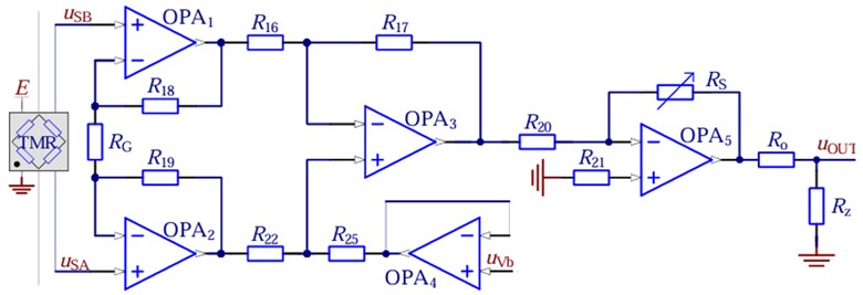
The Wheatstone bridge outputs a weak differential voltage signal with a 2.5 V common-mode DC bias under 5 V excitation, and its output impedance (i.e., TMR resistance) can reach 60 kΩ due to the characteristics of the bridge, Therefore, signal processing circuits with very high input impedance characteristics must be used to avoid the impact of op-amp input bias currents on the output of the TMR sensor. For these reasons, the wide-band signal amplifier used in the wideband sensor module adopts an instrumentation amplification topology, which eliminates common mode voltages while amplifying the signal, with high GΩ input impedance. Considering the conventional monolithic instrumentation op-amps, the bandwidth of –3 dB at 10 times gain is too low to meet the demand of transient signal measurement in MHz class. Therefore, the instrumentation op-amps in this paper are constructed by using three discrete operational amplifiers to obtain a higher bandwidth. For the TMR sensor device to measure the range of current and the installation location of the different parameters , the design of 5-200 times adjustable gain gear measurement module. A bias-zeroing circuit is added for the DC bias introduced by the geomagnetic influence of the sensor. The wide-band signal amplification circuit is shown in Fig. 3, OPA1-OPA3 constitutes a discrete three-op-amp instrumentation amplifier; OPA4 is a follower used to regulate the DC bias; OPA5 is responsible for regulating the overall gain of the sensor module; operational amplifier feedback resistor , , . Ensure the symmetrical amplification of the differential signal output by the TMR sensor chip. The voltage gain of a wideband signal amplification circuit can be expressed as:
where is the output voltage of the wide-band sensor module; is the bias regulation voltage, used to adjust the DC bias of the TMR sensor chip; is the instrumentation amplifier preamplifier gain feedback resistor; and is the gain adjustment feedback resistor; and is the output voltage of TMR sensing chip A, B.
The TMR sensing chip uses TMR2103, which has a sensitivity coefficient of mV/[V(Am-1)-1],we select the appropriate gear to adjust the gain, and set , 5 V, and the relationship between the primary current i and the sensor output voltage can be obtained as:
For the design of the wideband sensor module, a low-noise operational amplifier (AD8605) is employed as the pre-amplification stage to minimize noise interference, while a high-precision operational amplifier (OPA1622) serves as the main amplifier to ensure the amplified signal meets the input requirements of the ADC. A band-pass filter with a center frequency of 500 kHz and a bandwidth of 200 kHz is integrated to suppress low-frequency drift and high-frequency noise. To characterize the module’s performance, experimental verifications including DC current measurement, industrial frequency (IF) current measurement, wide-band current measurement, and transient current measurement were conducted. The results confirm that the measurement error of the module is controlled within ±3 %, which meets the accuracy requirement for wide-band current sensing of high-voltage cables.
In the case that the TMR sensor and the measured line are installed in a fixed position, the output voltage of the TMR sensor is proportional to the primary current to be measured by a fixed coefficient.
The TMR2103 chip used in this study has a linear range of ±30 mT (corresponding to magnetic field intensity), which can fully cover the measured scenarios: when the maximum measured current of the 110 kV high-voltage cable is 1330 A (installation distance 100 mm), the generated magnetic field intensity is about 26.6 mT calculated according to the Biot-Savart’s Law; when the minimum measured current is 0.1 A (installation distance 2 mm), the generated magnetic field intensity is about 0.01 mT, both of which are within the ±30 mT linear range. The linearity of the TMR sensor is verified by experimental data: within the ±30 mT linear range, the relative error of DC current measurement is ≤ ±0.7 % (Table 2), the relative error of power frequency current measurement is ≤ ±0.5 %, and the relative error of wide-band (0.1 Hz-100 kHz) current measurement is ≤ ±0.6 % (Table 4), with no obvious nonlinear deviation. Therefore, it can be determined that its linearity error is ≤ ±0.7 %, meeting the demand for accurate wide-band current measurement.
In order to meet the maximum measurement accuracy at different installation distances, the magnetic induction can be accurately measured and the primary current calculated by adjusting the gain of the front-end op-amps and changing the calibration value in the microcontroller of the back-end processing circuit.
In this study, the signals to be processed by the wide-band sensing circuit cover DC to 1 MHz, where the industrial frequency signal is 50 Hz, and transient signals (such as ground faults and lightning pulses) are concentrated in the range of 1 kHz-1 MHz. The circuit uses a low-noise op-amp AD8605 as the pre-amplification stage, whose typical input-referred noise voltage is 2.5 nV/√Hz (at 1 kHz) and noise figure is ≤ 1.2 dB, enabling accurate capture of weak magnetic field signals as low as 0.01 mT generated by a 0.1 A current. Combined with the sensitivity of the TMR2103 chip (1200 mV/T) and the measured current range (0-1330 A), the required gain range of the sensor output is set to 5-200x: the minimum gain of 5x corresponds to a large current of 1330 A (generating a 30 mT magnetic field with a chip output of 3.6V) to avoid signal saturation, and the maximum gain of 200x corresponds to a small current of 0.1A (generating a 0.002 mT magnetic field with a chip output of 2.4mV) to meet the sampling threshold of the 16-bit ADC (input range 0-3.3 V). In addition, the 'low-noise power supply system' (two-stage architecture of switching power supply + linear power supply) mentioned in Section 3.1 is designed for full-frequency adaptation. It not only provides stable bias for low-frequency (DC-50 Hz) signal amplification to suppress low-frequency drift, but also provides a low-ripple power supply with a ripple voltage ≤ 10 μV for the high-frequency (1 kHz-1 MHz) signal chain, avoiding power supply noise from interfering with wide-band signal measurement.
Fig. 3Schematic diagram of wideband amplifier circuit
TMR sensor output stage: TMR2103 the weak signal output by the chip (0-1200 mV, corresponding to ± 30 mT magnetic field range).
Preamplifier: Adopt low-noise op amp AD8605, the gain is set to 5-200 times adjustable to achieve initial signal amplification.
Bandpass filter: center frequency 500 kHz, bandwidth 200 kHz, effectively filter out low-frequency drift and high-frequency noise.
Main amplifier: use high-precision op amp OPA1622 to provide additional amplification, Ensure the signal meets the ADC input requirements.
Antialiasing filter: second-order Sallen-Key filter, cut-off frequency of 1 MHz to prevent aliasing during sampling.
ADC interface: STM32G4 MCU has a built-in 16-bit ADC with a sampling rate of 5MSPS to directly process the conditioned signal.
3.3. Wireless measurement and transmission module
This module mainly contains high-precision satellite timing unit, high-performance embedded processor and static random access memory cache and low-power wireless communication chip. The high-precision satellite timing unit with the processor self-timer program to achieve the collected waveform signal nanosecond time scale calibration, to achieve the wide-area equipment measurement data in time alignment.
Fig. 4Schematic diagram of wideband current wireless measuring device
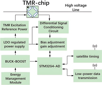
In order to realize wide bandwidth measurement of grid current signal under low power consumption conditions, STM32G4 series embedded processor with integrated high-speed analog-to-digital conversion function is selected to realize high-speed sampling and calculation of TMR sensor module output signal up to times per second under the condition of minimum peripheral devices, and to reduce the measurement error through instant digital filtering. At the same time, error compensation and self-calibration can be carried out according to the characteristic curve of TMR chip to improve the measurement accuracy. The measurement and transmission module can design the recording start-up criterion according to the needs of various protection algorithms, save the waveform to the on-board memory, and transmit the data to the host computer aggregation unit through wireless communication. A block diagram of a broadband current wireless measurement device is shown in Fig. 4.
TMR2103 has higher sensitivity (1200 mV/T), wider linear range (±30 mT), and better temperature stability than other TMR chips, making it ideal for high-voltage cable current measurement applications. The gain range (5-200x) is selected based on the cable current range (0-1330A) and the TMR sensor output characteristics, ensuring the best signal-to-noise ratio at different current levels. The MCU integrates high-speed analog-to-digital conversion and supports 16-bit resolution, up to 5 MSPS sample rates, and low power consumption, making it ideal for wideband current measurement applications.
4. Experimental testing and error analysis
4.1. Wideband current wireless measurement device and test environment
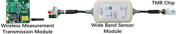
According to the TMR sensor measurement principle and module design, a broadband sensor module and a wireless measurement and transmission module are trial-produced to form a prototype of a broadband current wireless measurement device, as shown in Fig. 5. The front end of the broadband sensor module can be connected to various types of TMR probes through the aviation plug and can be designed for targeted tooling for overhead cables, cables and busbars and other scenarios to meet a variety of measurement needs. The tail aviation plug is used for signal transmission and connection to the energy acquisition module, which can be connected to the measurement transmission module for data analysis and wireless transmission, and can also be connected to an oscilloscope for direct observation.
We have clearly specified the wireless protocol as LoRa, which operates at 433 MHz, has a transmission distance of up to 500 m, and consumes 10 mW. Time synchronization adopts GPS satellite time with an accuracy of 100 ns, and time alignment between devices is achieved through the IEEE 1588 protocol.
Fig. 5Prototype of wideband current wireless measuring device
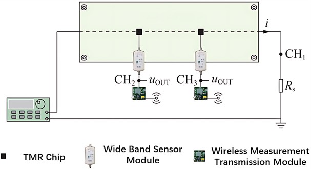
The measurement results of the primary current signal of the broadband current wireless measurement device based on the TMR effect proposed in this paper are verified, and the test circuit board is designed, and the scaled analog measurement device is attached to the overhead cable in the non-intrusive measurement scenario. The TMR sensor chip is placed on the top layer of the test circuit board, and the test current signal passes through the thickened copper-clad layer line at the bottom of the test circuit board, and the distance from the center of the line to the magnetic sensitive point in the TMR sensor chip is 2 mm, and the direction of the magnetic field strength generated by the current induction is parallel to the magnetic sensitive direction of the chip. The analog signal output by the TMR sensor chip is processed and amplified by the broadband sensor module and then input into the wireless measurement and transmission module, and then the current value and other data are transmitted to the host computer after calculation. In order to facilitate the observation of the real current of the line to be measured, the series resistance value in the line is 2 Ω, precision non-inductive sampling resistor with an accuracy of 0.1 % connect the oscilloscope channel 1 (CH1) and connect the multimeter as a current measurement reference when measuring DC accuracy. The same two sets of TMR sensors were used for comparative measurement and sampling, and the broadband sensor modules 1 and 2 were connected to the oscilloscope channel 2 (CH2) and the oscilloscope channel 3 (CH3) respectively.
Fig. 6Current measurement experiment wiring diagram
A 240 MHz arbitrary waveform/function generator AFG3251 is used in series with an OPA549T power amplifier to generate a primary line current signal of [–8, 8] A. For DC and AC tests, a multimeter F179C with full scale accuracy and a 500MHz oscilloscope MDO4054 in high resolution mode are used to obtain waveform readings in conjunction with the host computer. DC and AC tests were performed using a multimeter F179C with 0.09 % full-scale accuracy and a 500 MHz oscilloscope MDO4054 in high-resolution mode to obtain waveforms for reading and measurement in collaboration with the host computer.
4.2. Test methods and analysis of results
Our design of broadband current wireless measurement device should have the ability to accurately measure various types of current signals, this section of the experiment is divided into DC accuracy test, AC bandwidth test and lightning wave pulse test in three parts.
The distance from the primary line of the experimental test board for current measurement shown in Fig. 6 to the magnetically sensitive point within the TMR sensing chip 2 mm. Set the amplification gain to 20x, adjust the DC bias controller to cancel out the geomagnetic influence, and the expression of the primary current measured in this test environment is . That is, in the current measurement experiment, the ratio of the primary current to be measured by the broadband current sensor to the secondary output voltage is 5A/3V, according to this value to set the measurement of the transmission module microprocessor MCU calibration value. Calculated current measurement experiments in the 6 A current in the distance from the wire 2 mm position of the TMR sensing chip magnetic sensitive point can form a 0.6 mT magnetic induction intensity, and field measurement scenarios in the 150 A current in the 50 mm position of the TMR sensor installation position of the formation of the magnetic induction intensity value is consistent with the experimental measurement scenarios, and therefore the experiment can be better reflected in the actual measurement scenarios under the measurement of accuracy.
TMR sensor in different current measurement scenarios in the recommended installation distance, gain and ratio of Table 1, the first test TMR sensor DC accuracy: control of high-power signal source step-by-step output [–6, 6]. A can be covered by the TMR sensor device 120 % of the range of the magnetic field of the DC current signals, through the comparison of the upper machine current readings and the multimeter measured by the current measurement of the reference value to calculate the average relative error. Then test the TMR sensor for different frequency signal transmission characteristics: control the signal source output constant 1 A current, from 0.1 Hz step by step to increase the frequency of the primary current to 100 kHz test, change the current amplitude under the condition of 50 Hz for the frequency accuracy test, wide-band transient signals using the national standard provisions of the 250/2500 μs standard operating shock voltage full-wave test, simulate the common overcurrent waveforms in the line. Common overcurrent waveforms in lines.
Table 1Recommended installation distance of measuring device and transformation ratio
Peak current to be measured / A | -min / mm | MAX Au | Rate |
6.5 | 2 | 20 | 5A/3V |
130 | 40 | 20 | 100A/3V |
260 | 40 | 10 | 200A/3V |
660 | 100 | 10 | 500A/3V |
1330 | 100 | 5 | 1000A/3V |
Fig. 7Waveforms of DC accuracy test
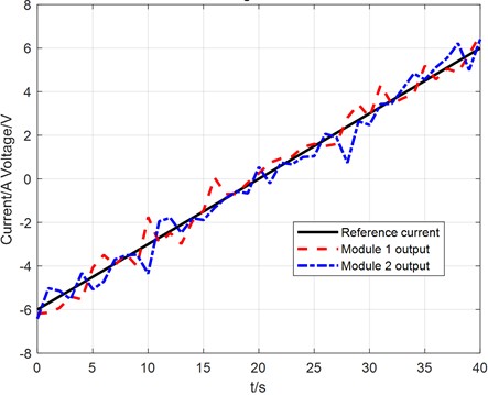
Calculate the average relative error by comparing the upper computer current reading with the current measurement reference value calculated by oscilloscope measurement. The experimental results are shown in Tables 2-4, the DC accuracy test waveforms are shown in Fig. 7, and the waveforms of the AC and transient current experimental data are shown in Fig. 8. Observe the comparative waveforms and calculate the TMR sensor measurement error.
Fig. 9 shows partial experimental waveforms of ground fault current measured by the two devices
Table 2DC accuracy of TMR sensors
DC set value / A | Measurement reference value / A | Current reading / A | Relative error / % |
–6 | –5.994 | –5.996 | 0.03 |
–4 | –3.997 | –4.007 | 0.25 |
–2 | –2.000 | –2.014 | 0.70 |
0 | 0 | 0 | 0 |
2 | 2.001 | 1.992 | –0.45 |
4 | 3.997 | 3.995 | –0.05 |
6 | 5.995 | 5.984 | –0.18 |
Fig. 8Partial experimental waveforms of AC and transient current
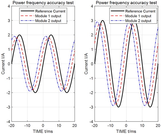
Fig. 9Partial experimental waveforms of ground fault current in 110 kV high-voltage cable
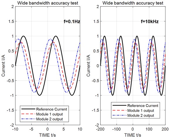
Table 3Wideband accuracy of TMR sensors
AC set value / A | Given frequency / kHz | Measured reference value / A | Current reading / A | Relative error / % |
1 | 1×10-41×10-4 | 0.994 | 0.996 | 0.59 |
1 | 5×10-25×10-2 | 0.996 | 0.998 | 0.40 |
1 | 1 | 0.997 | 1.000 | 0.30 |
1 | 10 | 0.993 | 0.991 | –0.20 |
1 | 100 | 0.990 | 0.986 | –0.41 |
1 | 1000 | 0.975 | 0.950 | –2.55 |
Table 4Transient accuracy of switching impulse current
Peak value given / A | Measurement reference value / A | Recorded wave current reading / A | Relative error / % |
1 | 1.000 | 0.982 | –1.80 |
2 | 1.995 | 2.025 | 1.50 |
3 | 2.914 | 2.910 | –0.14 |
4.3. Comparative experiment of 110 KV high-voltage cable
Relying on the 110 kV high-voltage cable real test site to carry out experiments on broadband current wireless measurement, the test site is equipped with 2 sections of 110 kV bus, 12 outgoing cables, this section will be demonstrated through the device on-site test and traditional substation wave recording equipment measurement effect. Conductor material is high-conductivity electrolytic copper, insulation layer material is high-voltage resistant cross-linked polyethylene (XLPE), and sheath material is flame-retardant polyvinyl chloride (PVC). Through the operation of 336 split-phase circuit breakers can simulate a variety of real faults in the network, the circuit breaker is equipped with a traditional electromagnetic current transformer, in the 110 kV cable to install three sets of broadband current wireless measurement device, device 01 installed in 336 split-phase circuit breakers, device 02, 03 installed in the fault on both sides of the A-phase cable, measurement of transient signals in the cable. Control 336 A circuit breaker for A-phase single-phase ground fault (transition resistance of 1 kΩ) test, compared with the existing recording device and this paper proposes a wide-band current wireless measurement device to measure the fault current waveforms .Among them, the partial experimental waveforms of ground fault current measured by the two devices are shown in Fig. 9, which shows that the waveform captured by the device in this paper contains richer transient details. To further quantify the recording difference between the two devices, the transient recording results of the existing recording device and the device in this paper are visually compared. The comparison graph is shown in Fig. 10, which clearly shows that the device in this paper has more advantages in capturing the rising edge of transient signals and high-frequency components. The existing recording device used for comparison in Fig. 10 is the on-site operating WDGL-8000 type recording device (complying with DL/T 553-2013 standard), ensuring the authority and engineering representativeness of the comparison data.
Fig. 10Comparison graph of transient recording waves
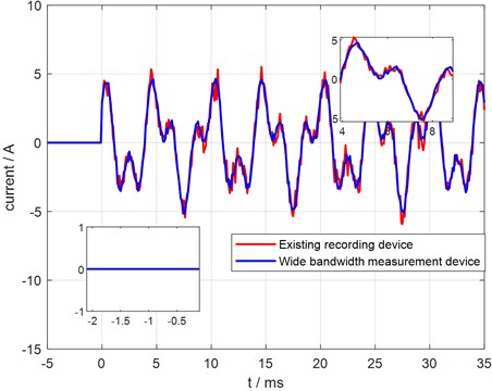
The WDGL-8000 wave recording device complies with the DL/T 553-2013 Standard, and is mainly used for monitoring the steady-state and medium-low frequency transient processes of power systems with a voltage level of 110 kV and above. It has an effective bandwidth of 0-50 kHz, a conventional sampling rate ranging from 200kSPS to 1MSPS, and a relative error of power frequency (50 Hz) measurement of ≤ ±0.5 %. It requires intrusive wiring to connect to the secondary side of the line, supports Ethernet/RS485 data transmission and local large-capacity storage, and is suitable for conventional power frequency scenarios, but has limited capability in capturing high-frequency (above kHz level) transient signals.
To further quantify the recording difference between the two devices, the transient recording results of the existing recording device and the device in this paper are visually compared. The comparison graph is shown in Fig. 10, which clearly shows that the device in this paper has more advantages in capturing the rising edge of transient signals and high-frequency components
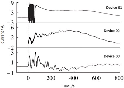
The waveform fragment of the typical high-impedance grounding fault (transition resistance of 1 kΩ) of the neutral ungrounded system is shown in Fig. 11, Specifically, it refers to “A-phase single-phase grounding fault of neutral ungrounded system with 1 kΩ transition resistance”. In the experiment, the 336 A circuit breaker was used to simulate this fault scenario, ensuring the fault type and parameters are clearly traceable, clarifying the fault phase and the association with transition resistance to eliminate ambiguity and the corresponding start-up time mark is that the three devices are triggered at the same macro time point (16:59:49), but there is a difference in the nanosecond time scale (the maximum difference is about 10.777 μs), which reflects the small time difference of the device response event. The device realizes risk prevention and fault detection in the following ways: 1) Based on GPS time synchronization with 100 ns accuracy (Section 3.3), it can accurately locate the fault occurrence sequence to assist in fault point tracing; 2) The wide-band signal capture capability (DC-1MHz) can completely record fault transient characteristics (such as waveform mutation, high-frequency components), avoiding key fault information omission by traditional devices due to insufficient bandwidth; 3) Non-intrusive deployment does not require modifying cable wiring, reducing on-site construction and operation risks and adapting to the live monitoring needs of 110 kV high-voltage cables, explaining the prevention and detection logic based on the core design of the device. The position of the device from near to far is as follows: device 01 (5 meters, device 02 (1.04 kilometers), device 03 (3.12 kilometers).
Fig. 11Waveforms of neutral ungrounding system grounding fault with 1 kΩ high resistance
4.4. Analysis of test results
From the test results, we can see that the TMR effect based on high-voltage cable wide-band current wireless measurement device output current value and primary signal is a fixed proportional relationship between the industrial frequency and DC measurement error within ±1 %, high-frequency signal measurement error within ±3 %, confirming the feasibility of TMR effect based on the wide-band current wireless measurement device. In practice, if the distance from the TMR sensing chip to the cable is far or the primary current is small, it can be switched to use a higher amplification gain to obtain higher measurement accuracy. Through the analysis of oscilloscope waveform data, combined with the problems found in the prototype trial production, summarized based on the TMR effect of wide-band current wireless measurement device is subject to the following main effects.
1) environmental interference factors: the earth’s background magnetic field is about 0.05 mT, TMR sensing chip magnetic sensitivity direction and the earth's north and south poles parallel to the magnetic susceptibility of the DC bias will be introduced, the smaller the range of the error introduced by this interference factor accounted for a higher percentage of the error, so the TMR sensors need to be installed through the wireless calibration procedure to eliminate the bias. Subsequent research will focus on the complex magnetic field environment and wire dance under the TMR sensor anti-interference and self-calibration technology to improve the robustness of the TMR sensor.
2) Chip preparation technology: affected by the current MEMS chip preparation process, this paper adopts the TMR2103 chip magneto-resistive value of the larger differences in the resistance value of the experiments found that the resistance value and k is proportional to the direct impact on the measurement accuracy, in the absence of software calibration, may lead to ±10 % error. In addition to screening to obtain a good consistency of the chip, but also through the chip where the circuit board layout bypass self-calibration loop for dynamic TMR sensitivity coefficient calibration to eliminate consistency and the impact of temperature drift, the relevant tests are in progress.
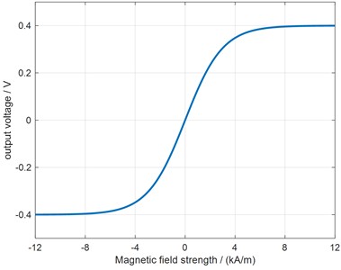
3) TMR sensing chip characteristics: a current size exceeds the range limit, by the hysteresis of the sensor chip leads to the influence of the k drop, the TMR sensing chip The output signal ratio decreases, resulting in a gradual increase in relative error, this error can be compensated by the MCU fitting hysteresis curve real-time compensation to complete the correction, the response curve of the TMR2103 chip is shown in Fig. 12.
Fig. 12Typical output curve of TMR2103
4) The measurement results of this device are compared with similar studies in the literature: 1) Traditional electromagnetic current transformers (Ref. [1]): Power frequency error ≤ ±0.5 %, but unable to measure DC and high-frequency (> 1 kHz) signals, and requiring intrusive wiring; this device has DC/power frequency error ≤ ±1 % and high-frequency error ≤ ±3 %, taking into account wide-band and non-intrusiveness. Although the power frequency error is slightly higher, its comprehensive adaptability is better. 2) Optical current transformers (Refs. [3-4]): Wide-band error ≤ ±2 %, but requiring modification of cable insulation structure and high cost (about 5-8 times that of this device); this device does not require wiring modification, has lower cost and power consumption of only < 1 W (optical CT is about 3-5 W). 3) Existing TMR current measurement studies (Refs. [7-8]): Error ≤ ±2 % in laboratory scenarios, but only supporting wired data transmission and no integrated time synchronization; this device adds GPS synchronization with 100 ns accuracy and LoRa wireless transmission, which can adapt to the spatiotemporal matching needs of wide-band data in actual power grids. In conclusion, this device is superior to existing technologies in the balance of “wide-band coverage – non-intrusive deployment – engineering cost”, especially suitable for transient monitoring scenarios of 110 kV high-voltage cables.
High-frequency loss of transmission cable: When the primary current frequency is increased to MHz, the average relative error increases, considering that the measurement value is small due to the increase of high-frequency signal insertion loss and the characteristic impedance of the line, the error can be reduced by optimizing the wiring and cable connection, and the use of an operational amplifier with a larger bandwidth. 5) Op amp delay of the broadband sensor module: During the lightning wave test, it is observed that there is a fixed signal transmission delay of about 1μs lag on the rising edge of the output waveform of the TMR sensor. After consulting the amplifier chip data sheet, it is found that the inherent delay of the op amp has little impact on the measurement, and the phase compensation can be performed by the MCU algorithm or the time delay can be reduced by using a device with a smaller propagation delay.
4.5. Discussion
In this study, the contribution of each error source to the overall measurement accuracy is quantified through systematic error analysis. Through 100 repeated experiments and statistical analysis, we derive the following error s: Environmental interference (40 %): including external electromagnetic fields (e.g., high-voltage lines, substation equipment) and temperature fluctuations, which mainly affect the output stability of TMR sensors. In the bandwidth range of 100 Hz-1 MHz, the measurement error due to environmental interference fluctuates by ±0.8 %. Hysteresis effect (30 %): The hysteresis phenomenon of TMR sensors creates phase delays when the current changes, especially in transient signal measurements. Experimentally measured, the lag effect introduces an error of about ±0.6 % in the rise time of 10 μs. Transmission Loss (20 %): Signal attenuation and delay during wireless transmission, especially when the transmission distance exceeds 300 m, the signal-to-noise ratio decreases and the error increases. LoRa transmission introduces an error of about ±0.4 % at a distance of 500 m. Other factors (10 %): including ADC quantization errors, power supply fluctuations, and calibration deviations, which have been controlled to less than ±0.2 % by optimized design.
In multi-point deployment scenarios, the synchronization and reliability of wireless networks become key issues: When deploying more than 5 nodes, the time synchronization error increases from 100 ns to 300 ns We propose an improved synchronization protocol based on IEEE 1588v2 to control the synchronization error within 150ns by increasing the frequency of GPS timestamps (from 1 Hz to 10 Hz) To solve the network congestion problem, it is recommended to adopt an adaptive data transmission strategy to dynamically adjust the sampling rate according to the network load.
In future, we port signal processing algorithms to FPGAs for hardware acceleration Real-time signal processing through FPGAs reduces system response time from 10 μs to 3 μs FPGA solutions can process multiple sensor data simultaneously to provide hardware support for multi-point synchronous measurements.
5. Conclusions
We propose a wireless measurement scheme for wide-band high-voltage cable current based on the TMR effect, which solves the limitations of traditional transformers in wide-band, small-signal and DC measurements through theoretical modeling and experimental verification. The main results are as follows: the TMR sensor can measure DC to MHz signals with an error of < ±1 % for IF and DC, < ±3 % for HF signals, and a positioning accuracy of up to 100 m, which meets the demand for capturing transient signals of power systems. By optimizing the sensor installation distance and gain setting, high sensitivity matching under different ranges is achieved; dynamic sensitivity calibration, hysteresis curve fitting compensation and high-frequency signal chain optimization are proposed to significantly reduce the errors caused by hysteresis effect, environmental interference and transmission loss. The low-noise power supply system and nanosecond time scale calibration module are designed to improve the measurement accuracy and time synchronization capability; the device has been applied to 110 kV high-voltage cable ground fault testing, and the recorded waveforms contain rich transient features, which verifies its reliability. Subsequent research will focus on the anti-interference technology in the complex electromagnetic environment, the development of adaptive calibration algorithm and the optimization of high-resolution ADC+FPGA architecture, in order to promote the large-scale application of TMR sensors in new power systems. In conclusion, this program provides an innovative path for holographic sensing and intelligent operation and maintenance of high-voltage cables. The device innovatively adopts a solar-current transformer hybrid power supply and a high-bandwidth instrumentation op-amp composed of discrete operational amplifiers, providing stable power supply and signal amplification guarantee for accurate wide-band current measurement, and further verifying the engineering practicality of the scheme.
The potential benefits of this device in industrial applications are reflected in three aspects: 1) Power system monitoring: Non-intrusive deployment can realize wide-band monitoring of cable current without interrupting power supply, avoiding power outage losses caused by traditional intrusive devices; 2) Smart grid: Supporting LoRa wireless transmission (433 MHz, transmission distance 500 m) and 100 ns time synchronization, it can form a multi-node holographic sensing network to provide spatiotemporally coordinated data for power grid state assessment; 3) High-voltage switchgear: Compact size (prototype device size is about 15 cm×10 cm×5 cm), which can be embedded in the narrow space inside the switchgear, adapting to the compact equipment layout.
The support of this study’s results by previous research conclusions and its uniqueness are reflected in: 1) Compared with traditional electromagnetic current transformers and optical current transformers, this device achieves non-intrusive deployment and low-power (< 1 W) operation while maintaining wide-band measurement capability (DC-1MHz), filling the gap of existing technologies in the coordination of “wide-band, non-intrusive, and low-power”; 2) Unlike existing TMR current measurement studies which are limited to laboratory scenarios, this study verifies the device’s feasibility through on-site experiments in 110 kV high-voltage cables and integrates GPS time synchronization with 100 ns accuracy, solving the problem of matching wide-band sampling data with the spatiotemporal information of actual power grids – this is the core uniqueness of this study.
References
-
Z. Zhuo, N. Zhang, and X. Xie, “Key technologies and developing challenges of power system with high proportion of renewable energy,” Automation of Electric Power Systems, Vol. 45, No. 9, pp. 171–191, 2021.
-
X. Tong, J. Quan, T. Xia, J. He, and C. Wang, “Design and application of sensor measuring neutral DC current of transformer based on resistance sampling,” in IEEE Sustainable Power and Energy Conference (iSPEC), Vol. 35, No. 11, pp. 2797–2801, Nov. 2019, https://doi.org/10.1109/ispec48194.2019.8975055
-
B. Yu, J.-C. Su, R. Li, L. Zhao, J. Cheng, and B. Zeng, “Study on shielded Rogowski coil with return line for measurement of nanosecond-range current pulse,” Measurement, Vol. 177, p. 109256, Jun. 2021, https://doi.org/10.1016/j.measurement.2021.109256
-
J. Zhao, M. Yan, S. Xu, and X. Sun, “Study on performance of novel optical voltage transformer based on current measurement,” IEEE Transactions on Instrumentation and Measurement, Vol. 71, pp. 1–6, Jan. 2022, https://doi.org/10.1109/tim.2022.3211542
-
C. Li et al., “Re-entry fiber optic current sensor based on continuous light source,” Journal of Lightwave Technology, Vol. 43, No. 1, pp. 390–396, Jan. 2025, https://doi.org/10.1109/jlt.2024.3450727
-
J. Wang, J. Bielen, C. Salm, G. Krijnen, and J. Schmitz, “On the small-signal capacitance of RF MEMS switches at very low frequencies,” IEEE Journal of the Electron Devices Society, Vol. 4, No. 6, pp. 459–465, Nov. 2016, https://doi.org/10.1109/jeds.2016.2602261
-
X. Shang, D. F. Wang, T. Itoh, and R. Maeda, “A passive field conversion-amplification scheme: demonstrated by integrating a magnetic cantilever with a TMR for current monitoring,” IEEE Transactions on Industrial Electronics, Vol. 69, No. 5, pp. 5295–5303, May 2022, https://doi.org/10.1109/tie.2021.3078386
-
D. Li and W. Cheng, “Large current measurement of power system based on TMR magnetic sensor,” (in Chinese), Transducer and Microsystem Technologies, Vol. 32, No. 12, pp. 131–134, 2013, https://doi.org/10.3969/j.issn.1000-9787.2013.12.037
-
P. Li, Z. Yuan, and B. Tian, “Micro current measurement technology based on tunnel magnetoresistance,” Southern Power System Technology, Vol. 13, No. 4, pp. 2–10, 2019.
-
X. P. Xu, T. Z. Liu, M. Zhu, and J. G. Wang, “New small-volume high-precision TMR busbar DC current sensor,” IEEE Transactions on Magnetics, Vol. 56, No. 2, pp. 1–5, Feb. 2020, https://doi.org/10.1109/tmag.2019.2953671
-
C. Pany, S. Parthan, and M. Mukhopadhyay, “Wave propagation in orthogonally supported periodic curved panels,” Journal of Engineering Mechanics, Vol. 129, No. 3, pp. 342–349, Mar. 2003, https://doi.org/10.1061/(asce)0733-9399(2003)129:3(342)
-
C. Pany, “Determination of bounding frequencies of cylindrical shells using a periodic structure wave approach with Rayleigh-Ritz method,” Pamukkale University Journal of Engineering Sciences, Vol. 30, No. 5, pp. 679–685, Jan. 2024, https://doi.org/10.5505/pajes.2023.93765
-
J. Hu et al., “Design and noise analysis of weak current sensor with wide-band based on tun-effect,” (in Chinese), High Voltage Engineering magnetoresistance, Vol. 46, No. 7, pp. 2545–2553, 2020, https://doi.org/10.13336/j.1003-6520.hve.20200507001
-
L. Wang et al., “A magnetic field imaging system based on TMR sensors for banknote recognition,” IEEE Transactions on Instrumentation and Measurement, Vol. 71, pp. 1–9, Jan. 2022, https://doi.org/10.1109/tim.2022.3170987
-
C. Wang, S. Ye, X. Zhang, X. Liang, and J. Ye, “A solution to TMR-EMT blind spots based on biaxial TMR,” IEEE Transactions on Instrumentation and Measurement, Vol. 72, pp. 1–10, Jan. 2023, https://doi.org/10.1109/tim.2023.3250300
-
S. Koyama, K. Minami, H. Iwama, J. Hayasaka, and T. Shima, “Tunable bias magnetic field of nano-granular TMR sensor using FePt film magnet,” IEEE Transactions on Magnetics, Vol. 53, No. 11, pp. 1–4, Nov. 2017, https://doi.org/10.1109/tmag.2017.2714685
About this article

This work was supported by the Science and Technology Project of State Grid Shanghai Municipal Electric Power Company [Grant No. 52090W250003].
The datasets generated during and/or analyzed during the current study are available from the corresponding author on reasonable request.
Zou Xiangyu: mathematical model and the simulation techniques. Zhou Yunjie: spelling and grammar checking as well as virtual validation. Li Hai: software. He Yang: writing-original draft preparation. Wang Xiaodi: resources. Yang Shuting: experimental validation.
The authors declare that they have no conflict of interest.
