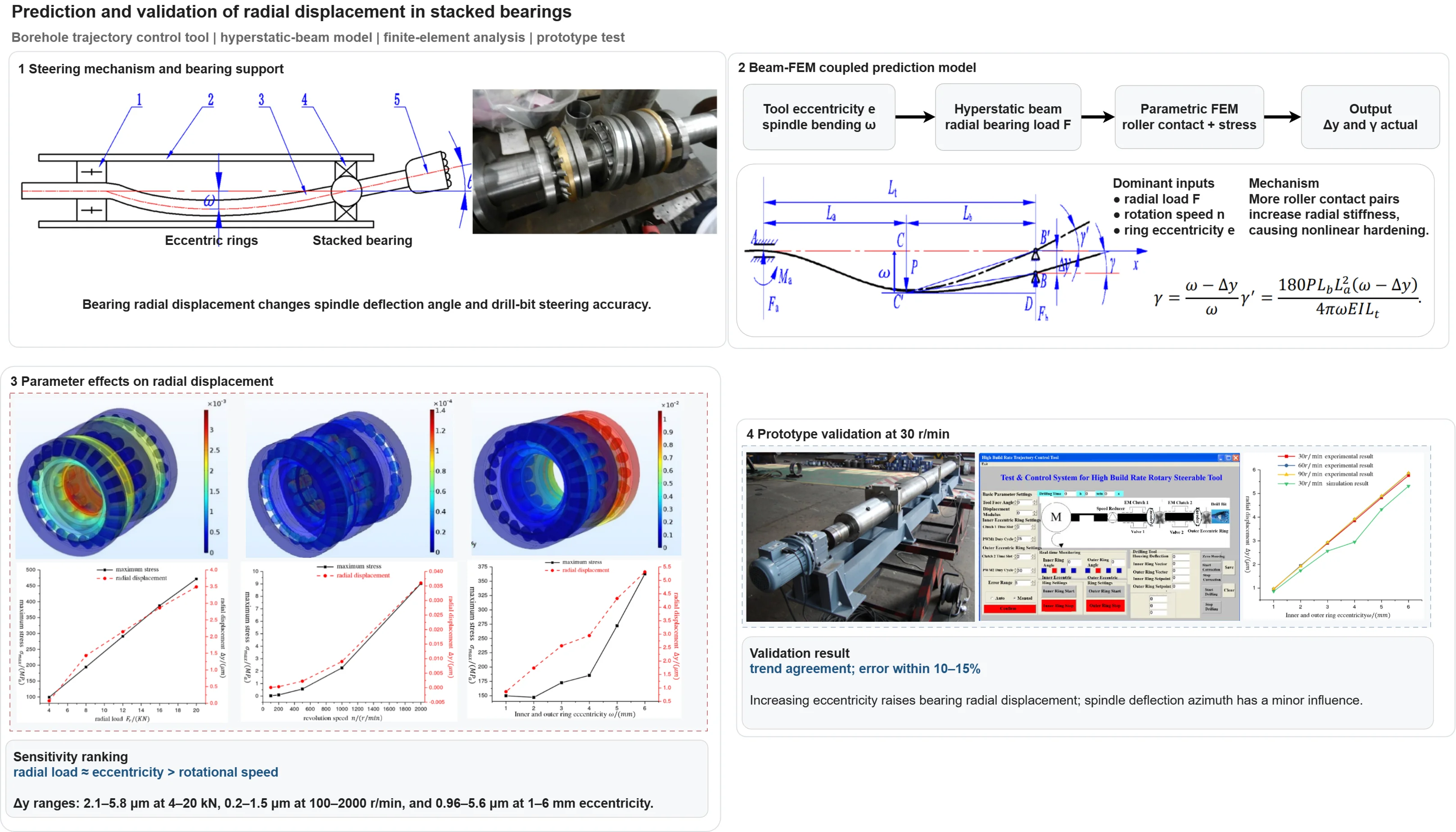
Abstract
With the decreasing of easy-to-exploit oil and gas resources, complex structure wells put forward higher requirements for wellbore trajectory control accuracy. As the core supporting part of the guiding tool, the radial displacement of the combined bearing directly affects the deflection accuracy of the spindle. In order to reveal the internal correlation mechanism between the radial displacement of the combined bearing and the accuracy of the spindle deflection control, this paper combines the statically indeterminate beam theory and the parametric finite element method to establish a spindle deflection prediction model considering multi-factor coupling. The influence of radial load, rotational speed and inner and outer ring eccentricity on the radial displacement of the combined bearing is systematically studied. The results show that the radial displacement of the combined bearing increases significantly with the increase of radial load, rotational speed and eccentricity. Especially under heavy load conditions, the change of the contact logarithm of the rollers inside the bearing leads to a nonlinear turning of the stiffness characteristics, showing obvious adaptive bearing characteristics. The prototype experiment shows that the variation trend of the simulation and the measured data is highly consistent under the condition of 30 r/min, and the error is controlled within 10 %-15 %, which verifies the accuracy of the model. This study not only quantifies the influence of key parameters on bearing displacement, but also provides a theoretical basis and parameter selection criteria for structural optimization design and accuracy improvement of rotary steering drilling tool combined bearings.
Highlights
- A hyperstatic-beam model links eccentricity, radial load, bearing radial displacement, and spindle deflection angle.
- Parametric finite element analysis shows radial displacement rises with load, speed, and eccentricity; load and eccentricity dominate.
- Changes in roller contact pairs produce nonlinear stiffness hardening, slowing displacement growth under high radial load.
- Prototype tests at 30 r/min validate the model, with simulation-measurement errors controlled within 10-15%.
1. Introduction
Crude oil and natural gas are non-renewable resources. Continuous exploration and development have led to a progressive decline in easily accessible reservoirs, while the conditions of existing reserves have become increasingly complex. This trend places more rigorous demands on drilling technologies. In particular, the exploitation of offshore oil fields and complex geological formations frequently requires the drilling of numerous directional and extended-reach horizontal wells, which relies on high-precision borehole trajectory control technology for accurate steering.
In rotary steering drilling systems, the stacked bearing constitutes a critical supporting component located in the annular space near the bit. It comprises two thrust spherical roller bearings and one spherical roller bearing, integrated via bearing spacers, to support the spindle’s operation. This assembly simultaneously withstands radial and axial loads, ensuring spindle stability during both rotation and deflection. Supported by the stacked bearing and driven by the deflection mechanism, the spindle axis undergoes controlled deflection, thereby adjusting the drill bit's orientation and enabling precise wellbore trajectory control. Consequently, the performance of the stacked bearing directly determines the operational accuracy and reliability of the entire rotary steering tool [1, 2].
Extensive research on bearing mechanics has been conducted worldwide. Demirhan et al. [3] employed the finite element method to analyze displacement distribution across the inner and outer rings of a cylindrical roller bearing, identifying heterogeneous distribution characteristics that may induce fatigue failure. Feng et al. [4] developed a theoretical model for load distribution in stacked bearings using Hertzian line elastic contact theory, complemented by finite element analysis. Their work indicated that radial loads induce radial displacement in the bearing, subsequently influencing tool steering accuracy. Hao et al. [5] established a finite element model for cylindrical roller bearings, validated it experimentally, and further analyzed the effects of environmental temperature, clearance, and load on displacement distribution. Their results underscored the significant influence of housing constraints and structural configuration on displacement behavior. Tong et al. [6] investigated tapered roller bearings via a Matlab simulation model, demonstrating that radial displacement increases with combined loads and rotational speed. Aschenbrenner et al. [7] proposed a novel variational simulation framework to determine load distribution and radial displacement in roller bearings. Cao et al. [8] developed an analytical model for excitation sources in spherical roller bearings, analyzing the influence of radial clearance on displacement response and enabling quantitative prediction under varying clearance conditions. Feng et al. [9] integrated Stribeck’s maximum rolling element load formula with Palmgren’s rolling bearing displacement formula to establish a mathematical relationship between load and displacement in stacked bearings. Jang et al. [10] used the finite element method to determine thermal deformation in ball bearings and solved for radial and axial displacement based on inter-ball force equilibrium. Mitrović et al. [11] conducted finite element analysis on SKF 6310 radial ball bearings, observing increased displacement with rising operating temperature. Yang et al. [12] developed a 3D numerical model for 6208 deep groove ball bearings to investigate the effects of radial/axial loads and inner/outer ring thickness on center displacement. Their results indicated negligible displacement variation within the 3.65-2.5 mm thickness range, but a sharp increase when thickness was reduced to 2.0 mm.
A synthesis of the existing literature indicates that current research on bearing load and displacement primarily focuses on single-bearing structures, emphasizing internal stress, deformation behavior, and influencing factors. However, systematic investigations into the mechanical behavior and displacement characteristics of stacked bearings, particularly those employed in deflecting spindles, remain limited [13].
Building on this research background and addressing the structural complexity of stacked bearings in steering tools, this study establishes a mechanical model for the spindle of a borehole trajectory control tool. The calculation model for the spindle deflection angle (i.e., the stacked bearing’s deflection angle) is derived by solving the statically indeterminate beam equation using the superposition method, thereby analyzing the influence of the stacked bearing’s radial displacement on the deflection angle. Subsequently, a parametric finite element model of the stacked bearing is developed to systematically investigate the effects of radial load, rotational speed, and inner–outer ring eccentricity on its radial displacement and equivalent stress. Finally, experimental studies are conducted using a tool prototype, collecting measured data for comparative validation against the finite element simulation results.
2. Stacked bearings
2.1. Working mechanism of the stacked bearing
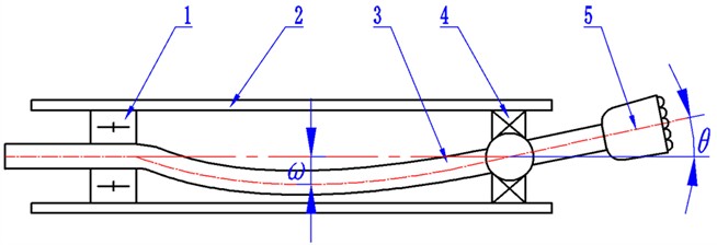
The stacked bearing is a critical component within the deflection system of the borehole trajectory control tool, installed near the bit at the tool’s lower end, as illustrated in Fig. 1. During operation, an eccentric control sub-assembly drives the rotation of two eccentric rings to push and bend the tool’s spindle in a designated direction [10]. Supported by the stacked bearing at the bottom, the spindle axis undergoes controlled deflection, thereby achieving precise orientation control of the drill bit.
Fig. 1Distribution of combined bearings in wellbore trajectory control tool: 1 – upper bearing; 2 – tool shell; 3 – mainshaft; 4 – combined bearing; 5 – drill
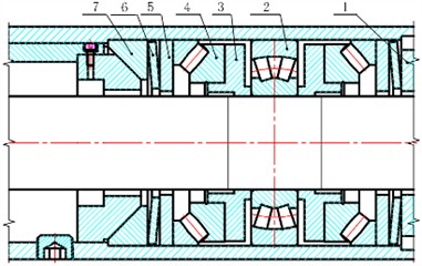
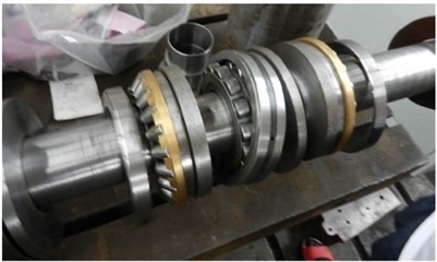
Functioning as the primary load-bearing element of the tool, the stacked bearing supports the spindle during both rotational and deflective motions. Its detailed configuration is shown in Fig. 2, consisting mainly of thrust spherical roller bearings, a spherical roller bearing, shaft rings, and disc springs. This bearing assembly is mounted near the bit at the tool’s lower end. Disc springs are installed at both the upper and lower ends, maintaining continuous contact with the two sets of back-to-back thrust spherical roller bearings inside the assembly. The assembly procedure is as follows: first, the disc spring thrust block is installed, followed by the sequential stacking of the disc spring, disc spring washer, thrust spherical roller bearing, bearing spacer, spherical roller bearing, another bearing spacer, thrust spherical roller bearing, disc spring washer, and disc spring. Finally, the disc spring compression washer is installed. Upon completion, the disc spring compression washer compresses the disc springs, ensuring that the two sets of thrust spherical roller bearings remain in a preloaded state. This design eliminates axial clearance and provides a consistent axial load.
Fig. 2Structure diagram of combined bearing: 1 – disc spring compression washer; 2 – aligning roller bearing; 3 – bearing washers; 4 – thrust self-aligning roller bearing; 5 – disc spring washer; 6 – disc spring; 7 – disc spring thrust block. Photo by WANG Weiping on July, 2025 at the Metalworking Practice Base, Yangtze University
When the tool spindle deflects, the bearing spacers and the inner ring of the spherical roller bearing in direct contact with it undergo synchronous deflection. In this condition, the outer ring raceways of the two thrust spherical roller bearings collectively form an outer spherical surface, while the outer ring raceway of the central spherical roller bearing constitutes an inner spherical surface. The spindle achieves stable directional deflection through the cooperative support of this dual-spherical surface configuration.
2.2. Spindle deflection mechanical model
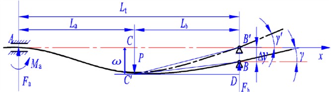
The deflection of the stacked bearing is regulated by a control sub-assembly. This sub-assembly drives the rotation of two eccentric rings to bend the spindle in a predetermined direction, thereby enabling precise control of the drill bit's orientation. In this deflected state, the spindle axis can be treated as a deflection curve. Accordingly, its mechanical model is simplified as a beam with hinged supports. Fig. 3 presents the force analysis, from which the following equation is derived based on static equilibrium conditions:
where and are the support forces exerted on the spindle by the needle roller bearing and the stacked bearing, respectively (N); and are the distances from the eccentric ring to the needle roller bearing and the stacked bearing, respectively (m); is the distance between the needle roller bearing and the stacked bearing (m); is the deflection load applied to the spindle by the eccentric ring (N); is the torque at the needle roller bearing (N∙m).
Fig. 3Calculation model of deflection angle of combined bearing
The static equilibrium equations of the tool spindle reveal that the number of unknown constraint forces exceeds that of independent equations. Thus, the established mechanical model constitutes a statically indeterminate beam problem. A supplementary equation is formulated based on the deformation compatibility condition of the beam:
where is the deflection at point B (m); is the deflection at point B under force alone (m); is the deflection at point B under force alone (m).
The superposition method yields the load at the stacked bearing, the deflection angle of the drill bit (i.e., the stacked bearing's deflection angle), and the relationship between the deflection load and the maximum deflection :
where is the deflection angle of the stacked bearing without considering radial displacement (°); is the maximum spindle deflection controlled by the deflection mechanism (m); is the elastic modulus of the spindle (Pa); is the moment of inertia of the cross-section (m4); is the spindle diameter (m).
2.3. Effect of radial displacement on deflection angle
During the slide-steering process, the stacked bearing of the borehole trajectory control tool deflects and sustains substantial loads. The radial clearance within the spherical roller bearing of the stacked bearing, coupled with the applied radial load, induces a radial displacement in the rotational axis of the stacked bearing. This displacement influences the bearing’s deflection angle. Given that the deflection angle is typically very small, the approximations and hold. Accounting for the radial displacement , the deflection angle of the stacked bearing becomes:
The theoretical derivation shows that the radial displacement of the combined bearing is the direct factor that affects the deflection angle of the spindle and determines the guidance accuracy of the drill bit. Therefore, in order to accurately predict and control the bit pointing, it is necessary to quantify the radial displacement of the combined bearing under different working conditions.
2.4. Definition of key parameters
In order to facilitate the subsequent analysis, the main parameters involved in the paper are summarized in Table 1.
Table 1Symbols and definitions of main parameters
Parameter | Implication | Unit | Value ranges |
Bias load applied by eccentric ring | m | Determined by eccentricity | |
Radial bearing force at the combined bearing | N | 4000-20000 | |
Distance from eccentric ring to needle roller bearing | m | Structure fixed value | |
Distance from eccentric ring to combined bearing | m | Structure fixed value | |
Distance from needle roller bearing to combined bearing | m | Structure fixed value | |
Elastic modulus of spindle | GPa | 207 | |
Inertia moment of spindle section | m4 | Calculated by diameter | |
Maximum deflection of spindle | m | 0-0.006 | |
Theoretical deflection angle without considering radial displacement | ° | Calculated by Eq. (4) | |
Radial displacement of combined bearing | μm | 0.96-5.6 (experimental value) | |
The actual deflection angle after considering the radial displacement | ° | Calculated by Eq. (7) |
3. Finite element analysis
Given the limitations of traditional methods, such as model complexity and solution difficulties, in determining the internal load and displacement of stacked bearings, this study establishes a quasi-static analysis model using finite element analysis software. This model is employed to systematically investigate the influence of key factors, including radial load, rotational speed, and inner-outer ring eccentricity, on the mechanical characteristics and radial displacement of the stacked bearing.
3.1. Finite element model
To ensure convergence and computational efficiency in the finite element simulation, the stacked bearing model was simplified as follows: the bearing spacer, the inner rings of the thrust spherical roller bearings, and the inner ring of the spherical roller bearing were geometrically merged into a single continuous entity. This simplification reduces the influence of minute structural features on computational stability. A parametric model was created based on actual dimensions and underwent mesh independence verification. Local mesh refinement was applied to critical contact regions. The final model comprises 343,976 elements, with a minimum element quality of 0.12, meeting the accuracy requirements for engineering calculations.
Fig. 4Combined bearing model and meshing
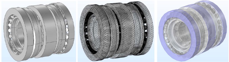
The material parameters for the stacked bearing were defined as follows: elastic modulus 207 GPa, Poisson’s ratio 0.3, and density 7800 kg/m3. To monitor key responses during simulation, displacement probes were placed on the inner ring of the stacked bearing, and stress probes were deployed throughout the entire domain to record inner ring displacement and the global maximum stress. Contact pairs were defined between all rollers and their corresponding inner/outer raceways, with a dry friction coefficient of 0.2 assigned to the contacts. A nonlinear solver was used for the numerical solution, with the relative tolerance set to 1. By applying different operational loads and constraints to the inner and outer rings, the stress and deformation responses of the stacked bearing under various working conditions were simulated and analyzed.
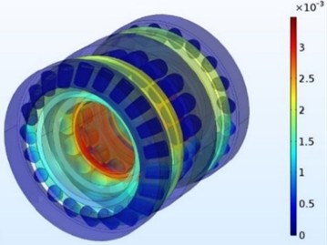
3.2. Influence of radial load on the stacked bearing
In the finite element model of the stacked bearing, fixed constraints were applied to the outer rings of both the thrust spherical roller bearings and the spherical roller bearing. Concurrently, radial loads of 4000 N, 8000 N, 12000 N, 16000 N, and 20000 N were applied along the -direction to the inner ring. The variations in stress and radial displacement of the stacked bearing under these different load levels are presented in Fig. 5.
Fig. 5The relationship between radial displacement and maximum stress of combined bearing and radial load
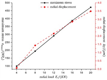
The simulation results show that the radial displacement and the maximum stress increase monotonically with the increase of load. It is worth noting that when the load reaches 8000 N, the growth slope of the displacement curve shows a significant turning point : when the load increases from 4000 N to 8000 N, the displacement increases by 2.2 μm, while when the load increases from 8000 N to 12000 N, the displacement only increases by 0.8 μm. This nonlinear hardening characteristic is derived from the step increase of the contact logarithm of the roller in the self-aligning roller bearing-only part of the roller is loaded under light load, and the stiffness is low. When the load is heavy, more rollers are involved in contact, and the equivalent radial stiffness is improved, thus inhibiting the further growth of displacement. This phenomenon reveals the adaptive bearing characteristics of the combined bearing, and the enlightenment to structural optimization is that the stiffness turning point can be matched with the common load interval by adjusting the number of rollers or preload, so as to reduce the radial displacement.
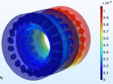
3.3. Influence of rotational speed on the stacked bearing
To analyze the influence of rotational speed on the mechanical behavior of the stacked bearing, a rotating reference frame encompassing all rollers was established within the finite element model, with the rotation axis defined as the -axis. Centrifugal loads corresponding to the rotational speed were applied to this frame, while the outer rings of both the thrust spherical roller bearing and the spherical roller bearing were constrained. Simulations were conducted at rotational speeds of 100 r/min, 200 r/min, 500 r/min, 1000 r/min, and 2000 r/min.
Fig. 6The relationship between radial displacement and maximum stress of combined bearing and rotational speed
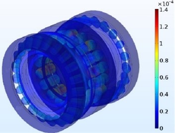
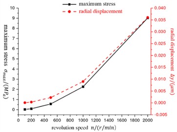
Fig. 6 illustrates the stress and radial displacement distribution in the stacked bearing across these different rotational speeds. The results show that the centrifugal force generated by the rollers orbiting the bearing axis causes them to disengage from the inner ring and maintain contact with the outer ring. As a result, both the radial displacement and the maximum equivalent stress of the stacked bearing exhibit a significant increasing trend with rising rotational speed.
3.4. Influence of inner-outer ring eccentricity on the stacked bearing
The wellbore trajectory control tool induces directional bending deformation of the main shaft by adjusting the relative angle of the inner and outer eccentric rings, thereby changing the maximum deflection of the shaft at the eccentric ring.
To ensure the accuracy of the boundary conditions for the finite element simulation, a combined approach of theoretical calculation and numerical simulation was adopted. Specifically, for inner and outer ring eccentricities ranging from 1 to 6 mm, Eq. (3-6) derived in the previous section were first used to calculate the corresponding theoretical deflection angle and the radial load acting on the combined bearing. These theoretical values were then applied as the load and angular displacement boundary conditions in the finite element model. On this basis, under a spindle speed of 30 r/min, the influence of eccentricity variations on the mechanical response of the combined bearing was simulated and analyzed.
Fig. 7The relationship between radial displacement and maximum stress of combined bearing and eccentricity
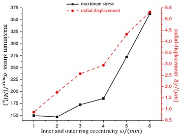
The simulation results are shown in Fig. 7. The radial displacement increases monotonously with the increase of eccentricity, but the maximum stress is slightly lower than that of 1 mm when the eccentricity is 2 mm. This is due to the increase of load at 2 mm eccentricity, which just makes the self-aligning roller bearing add two pairs of rollers to participate in contact, sharing part of the load and improving the stress distribution. This phenomenon suggests that in the selection of clearance, the expected eccentricity range and load size should be combined to make the change of roller contact state as smooth as possible, so as to avoid the displacement fluctuation caused by the sudden change of contact logarithm.
3.5. Parameter sensitivity analysis
In order to quantify the influence of various factors on the radial displacement, the simulation results under different parameter changes are arranged in Table 2. The data in the table show that the radial load and eccentricity have the most significant influence on the radial displacement, and the influence of the rotational speed is relatively small, but the three are positively correlated. This analysis can provide a reference for the working condition matching and structural optimization of the combined bearing.
Table 2The influence of key parameters on radial displacement
Parameter | Variation range | Radial displacement variation range / μm | Sensitivity |
Radial load | 4000-20000 N | 2.1-5.8 | High |
Revolution speed | 100-2000 r/min | 0.2-1.5 | Mid |
Eccentricity | 1-6 mm | 0.96-5.6 | High |
4. Experimental verification
Building on the preceding analysis, which revealed the influence of radial load, rotational speed, and inner-outer ring eccentricity on the radial displacement of the stacked bearing, this chapter presents an experimental investigation to validate the effectiveness of the established quasi-static simulation model. The radial displacement of the stacked bearing was measured under varying spindle deflection amounts and rotational speeds, with particular attention to the effects of different spindle deflection directions. The experimental data were subsequently compared with the simulation results for verification.
4.1. Experimental setup and measurement principle
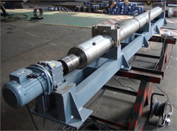
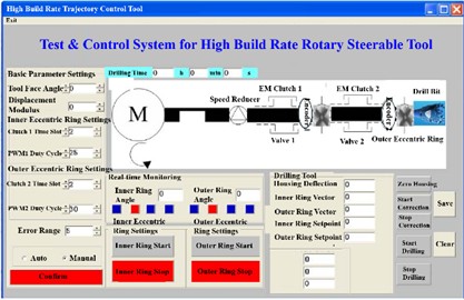
The prototype of the borehole trajectory control tool used in this study is shown in Fig. 8. Its key technical specifications include a design build-up rate of 8°/30 m, a maximum rotational speed of 200 r/min, and a temperature resistance of 125 °C. This prototype precisely controls the maximum spindle deflection within a 6 mm range in any direction between 0° and 360° by actuating its built-in eccentric rings. A dedicated control and testing system is integrated for this purpose.
Fig. 8Well trajectory control tool prototype and software interface. Photo by WANG Weiping on July, 2025 at the Metalworking Practice Base, Yangtze University
The direct measurement of radial displacement is impeded by the tool's confined internal space and potential interference from bearing vibration and tilt. To address this, a specialized measurement sub, illustrated in Fig. 9, was designed. This sub features four measurement heads uniformly distributed radially. The eddy current displacement sensors embedded within these heads accurately detect displacement in the vertical direction. The actual deflection angle of the stacked bearing is then calculated from these measurements, and finally, the radial displacement of the stacked bearing is derived by synthesizing Eq. (4) and Eq. (7).
Fig. 9Radial displacement measurement section and its measuring principle diagram. Photo by Wang Weiping on July, 2025 at the Metalworking Practice Base, Yangtze University
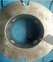
a) Structure
b) Measurement principle diagram
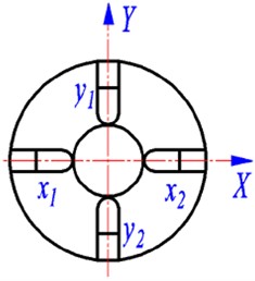
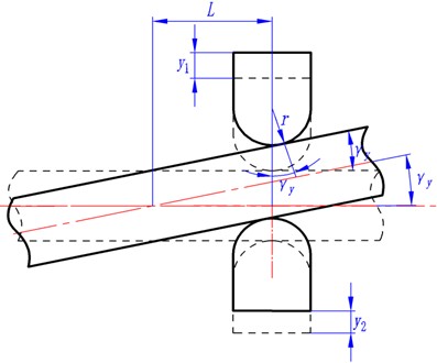
A schematic diagram of the deflection angle in the -direction is provided in Fig. 10, where represents the distance from the measurement sub to the stacked bearing, and denotes the contact arc radius of the measurement head. The following relationship is obtained from the geometry:
Similarly, for the -direction:
By combining Eqs. (8-9), the actual deflection angle of the stacked bearing is determined as:
The radial displacement of the stacked bearing is then solved by simultaneously applying Eq. (7) and Eq. (10):
Fig. 10Deflection angle measurement principle
4.2. Experimental procedure
To systematically investigate the influence of various factors on the radial displacement of the stacked bearing while effectively controlling experimental error, the testing sequence adhered to the following variable control order: first setting the tool spindle speed, then the tool deflection azimuth, and finally adjusting the inner-outer ring eccentricity. The spindle speed was incremented only after completing all experimental measurements at the current speed level. The detailed experimental procedure consisted of the following steps:
(1) The borehole trajectory control tool was mounted on the test bench. After leveling calibration, the bench output shaft was connected to the tool spindle via a coupling.
(2) The radial displacement measurement sub was installed. The tool control and signal interfaces were connected to the corresponding ports on the test bench, followed by verification of the communication link and calibration of the sensor range.
(3) The variable-frequency drive was activated, the gearbox was engaged to the required gear, and the spindle speed was set through the downhole tool dynamic simulation system before starting the drive motor.
(4) The tool’s eccentric rings were reset to the zero position with the deflection azimuth set to 0°. After the equipment operated steadily for one minute, the displacement sensors in all four directions were tared.
(5) The tool eccentricity was set to 1 mm. Upon stabilization of the spindle deflection motion, the system continued running for one minute, after which the variation in radial displacement at the stacked bearing was acquired and calculated over a subsequent two-minute period.
(6) The inner-outer ring eccentricity was gradually increased, repeating step (5) until radial displacement measurements for all specified eccentricity levels at the current rotational speed and deflection azimuth were completed.
(7) The tool deflection azimuth was progressively changed, repeating step (6) to systematically obtain radial displacement data corresponding to different azimuths at that rotational speed.
(8) The spindle speed was incrementally increased, repeating step (7) until all experimental measurements under the predetermined speed conditions were finished.
(9) The raw experimental data were exported for subsequent processing and analysis.
4.3. Test results and analysis
With the spindle speed held constant at 30 r/min, systematic measurements were conducted to determine the variation of the stacked bearing’s radial displacement with inner-outer ring eccentricity at four representative deflection azimuths: 0°, 90°, 180°, and 270°. Fig. 10 summarizes the results.
Fig. 11Combined bearing radial displacement under the spindle speed of 30 r/min
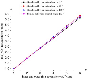
The results show that when the eccentricity is 1mm, the radial displacement is the smallest, about 0.96 μm; when the eccentricity increases to 6mm, the radial displacement reaches the maximum value, which is about 5.6 μm. The radial displacement of the combined bearing increases significantly with the increase of the eccentricity of the inner and outer rings, while the influence of the spindle deflection azimuth angle on the radial displacement is relatively small.
4.4. Comparative analysis of simulation and experimental results
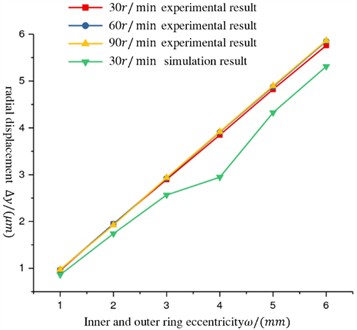
To validate the effectiveness of the quasi-static finite element model, a comparative analysis was performed between the simulated and experimentally measured radial displacements of the stacked bearing under different inner-outer ring eccentricities, all at a spindle speed of 30 r/min. Comparative results are presented in Fig. 12.
The analysis shows that the two trends are consistent, and the error is basically within 10 %-15 %, which verifies the effectiveness of the finite element model. However, at the eccentricity of 4 mm, the simulation results fluctuate, while the experimental curve remains smooth. The difference is due to the step change of the contact logarithm of the roller in the simulation model. In the actual experiment, due to the continuous rotation of the bearing, the pre-tightening force of the disc spring and the internal structural constraints of the tool, the transition of the contact state of the roller is more continuous. This comparison suggests that in the correction of control algorithm, the empirical compensation factor based on experimental data can be introduced, or the dynamic model considering the continuous change of contact state can be used to improve the accuracy of guidance accuracy prediction.
Fig. 12Experimental results compared with the results of the analysis
5. Conclusions
1) Theoretical Contribution: Based on the hyperstatic beam theory, a quantitative mapping model linking tool eccentricity, radial load, and bearing radial displacement was established. This model bridges the gap in traditional steering accuracy analysis where the influence of bearing flexible deformation is often neglected, providing a theoretical basis for high-precision wellbore trajectory control.
2) Key Findings and Mechanism: Finite element analysis reveals that the radial displacement and maximum equivalent stress of the combined bearing increase significantly with radial load, rotation speed, and eccentricity. Notably, a characteristic of non-linear stiffness hardening was observed, which is induced by the change in the number of roller contact pairs under increasing loads. This finding elucidates the physical mechanism where the displacement growth rate slows down under heavy load conditions, indicating the adaptive load-bearing capacity of the combined bearing.
3) Model Validation: The experimental results from the prototype closely matched the simulation data in trend, with a relative error controlled within 10 %-15 %. This validates the accuracy of the proposed quasi-static simulation method, demonstrating its effectiveness as a predictive tool for analyzing the mechanical behavior of steering tools under complex working conditions.
4) Engineering design criteria : In structural optimization, by adjusting the number of rollers or preload, the stiffness turning point is matched with the common load range, and the radial displacement is reduced ; in the selection of clearance, combined with the expected eccentricity range and load size, the appropriate clearance is selected to avoid the displacement fluctuation caused by the sudden change of contact logarithm. The compensation factor based on experimental data or the establishment of continuous contact model are introduced in the correction of control algorithm to improve the accuracy of guidance accuracy prediction.
References
-
D. Feng et al., “Research on control of steering movement of well trajectory control tool,” (in Chinese), Oil Field Equipment, Vol. 46, No. 1, pp. 6–10, Jan. 2017, https://doi.org/10.3969/j.issn.1001-3482.2017.01.002
-
D. Feng et al., “Failure analysis and optimization of cantilever bearing of borehole trajectory control devices,” (in Chinese), Science Technology and Engineering, Vol. 16, No. 16, pp. 179–182, 2016.
-
N. Demirhan and B. Kanber, “Stress and displacement distributions on cylindrical roller bearing rings using FEM,” Mechanics Based Design of Structures and Machines, Vol. 36, No. 1, pp. 86–102, Nov. 2008, https://doi.org/10.1080/15397730701842537
-
L. Shi et al., “Analysis of loading distribution for SRB and TSRB combined bearing,” Scientia Iranica, Vol. 29, No. 2, pp. 478–485, 2022.
-
X. Hao, X. Gu, X. Zhou, X. Liao, and Q. Han, “Distribution characteristics of stress and displacement of rings of cylindrical roller bearing,” Proceedings of the Institution of Mechanical Engineers, Part C: Journal of Mechanical Engineering Science, Vol. 233, No. 12, pp. 4348–4358, Dec. 2018, https://doi.org/10.1177/0954406218820551
-
V.-C. Tong and S.-W. Hong, “Characteristics of tapered roller bearing subjected to combined radial and moment loads,” International Journal of Precision Engineering and Manufacturing-Green Technology, Vol. 1, No. 4, pp. 323–328, Oct. 2014, https://doi.org/10.1007/s40684-014-0040-1
-
A. Aschenbrenner, B. Schleich, S. Tremmel, and S. Wartzack, “A variational simulation framework for the analysis of load distribution and radial displacement of cylindrical roller bearings,” Mechanism and Machine Theory, Vol. 147, p. 103769, May 2020, https://doi.org/10.1016/j.mechmachtheory.2019.103769
-
M. Cao and J. Xiao, “A comprehensive dynamic model of double-row spherical roller bearing-model development and case studies on surface defects, preloads, and radial clearance,” Mechanical Systems and Signal Processing, Vol. 22, No. 2, pp. 467–489, Feb. 2008, https://doi.org/10.1016/j.ymssp.2007.07.007
-
L. Shi, J. Wang, Z. Yang, K. Luo, H. Zhang, and D. Feng, “Influence of a combined bearing on the buildup rate of a wellbore trajectory control tool,” Journal of Advanced Mechanical Design, Systems, and Manufacturing, Vol. 14, No. 7, Jan. 2020, https://doi.org/10.1299/jamdsm.2020jamdsm0109
-
G. H. Jang et al., “Analysis of dynamic characteristics of a HDD spindle system supported by ball bearing due to temperature variation,” Microsystem Technologies, Vol. 9, No. 10, pp. 243–249, Dec. 2003, https://doi.org/10.5050/ksnvn.2003.13.10.805
-
R. Mitrovic, I. Atanasovska, N. Soldat, and D. Momcilovic, “Effects of operation temperature on thermal expansion and main parameters of radial ball bearings,” Thermal Science, Vol. 19, No. 5, pp. 1835–1844, Jan. 2015, https://doi.org/10.2298/tsci141223091m
-
L. Yang, S. Deng, and H.-X. Li, “Numerical analysis of loaded stress and central displacement of deep groove ball bearing,” Journal of Central South University, Vol. 23, No. 10, pp. 2542–2549, Dec. 2016, https://doi.org/10.1007/s11771-016-3315-6
-
S. S. Peng, “Contact stress analysis for self-aligning bearings of guide drilling system,” Bearing, No. 12, pp. 7–9, 2014.
About this article

The authors have not disclosed any funding.
The datasets generated during and/or analyzed during the current study are available from the corresponding author on reasonable request.
Guo Peng-Gao: conceptualization, investigation, writing-original draft preparation, writing-review and editing. Shi Lei: project administration, supervision. Yu Yan-fei: resources. Zhou Zhan: methodology. Mao Dian-Ren: formal analysis.
The authors declare that they have no conflict of interest.
