Abstract
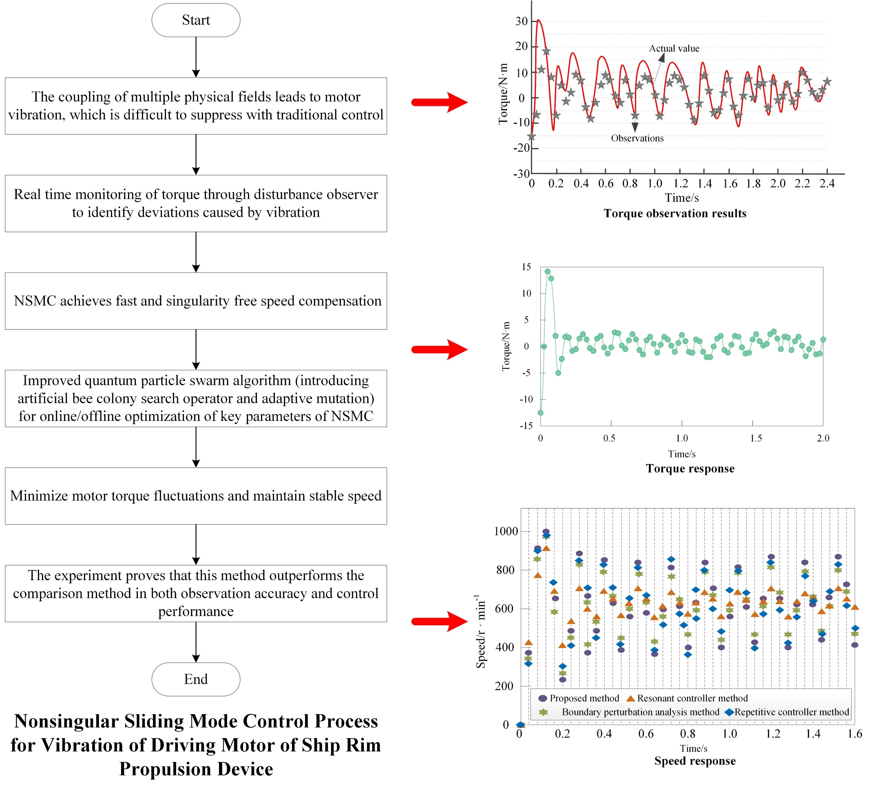
Owing to its unique structure, the driving motor of a ship’s rim propulsion device is subject to coupling effects from multiple physical fields. This makes it difficult for conventional control methods to effectively suppress vibrations caused by high-amplitude, complex harmonics, leading to poor speed and torque control performance. Therefore, a vibration suppression method based on disturbance observer combined with non singular sliding mode control is proposed. First, a disturbance observer is constructed to monitor motor torque in real time and accurately capture torque fluctuations induced by vibration. Secondly, design a non singular sliding mode controller to adaptively and quickly adjust the motor speed when vibration is detected. Finally, the quantum particle swarm algorithm, enhanced by the artificial bee colony algorithm, is used to optimize the controller parameters, thereby improving robustness and accuracy under multi-physics field coupling. The experimental results show that this method can accurately observe the motor torque and quickly stabilize the speed between 500 r/min-800 r/min under vibration state, with the smallest torque fluctuation amplitude. This result holds important scientific significance: it validates the effectiveness of nonsingular sliding mode control combined with intelligent optimization algorithms in decoupling multi-physics field interactions and suppressing complex electromagnetic excitation vibrations, offering a new control perspective for understanding motor dynamics under extreme operating conditions. In terms of application value, this method significantly enhances the dynamic response speed and steady-state accuracy of the driving motor, directly improving propulsion efficiency and maneuverability. It also effectively reduces fatigue wear on mechanical components, extends equipment life, and lowers operation and maintenance costs throughout the ship’s life cycle. In the future, we will explore integrating this control strategy with energy efficiency optimization for propulsion devices and investigate predictive vibration suppression methods based on digital twins to achieve smarter, more efficient health management of ship propulsion systems.
Highlights
- A disturbance observer is designed to monitor the driving motor torque in real time, enabling accurate capture of torque fluctuations induced by multi-physics field coupling vibrations in ship rim propulsion devices.
- A nonsingular sliding mode controller is developed to achieve fast, chatter-free speed compensation when vibration is detected, significantly improving dynamic response and steady-state accuracy.
- An improved quantum particle swarm optimization algorithm enhanced by artificial bee colony mutation is proposed to globally optimize controller parameters, enhancing robustness and control precision under complex operating conditions.
1. Introduction
As an innovative form of electric propulsion, rim propulsion devices are gradually being adopted in various high-end ships. Unlike traditional shaft propulsion systems (where the main engine drives the central propeller through a long axis system), the rim propulsion device [1] adopts rim drive technology, in which the stator of the motor is embedded in the guide tube, and the rotor is directly integrated on the outer rim of the propeller blade, forming a highly compact motor propeller integrated unit. This shaftless design eliminates energy loss and noise caused by long axis transmission, and has theoretical advantages such as high hydrodynamic efficiency, high space utilization, and strong maneuverability. However, it is precisely this special structure that makes the operating environment of the driving motor extremely harsh: the air gap magnetic field between the motor stator and rotor is not only affected by the electromagnetic force itself, but also by the strong coupling interference of multiple physical fields such as mechanical deformation of the wheel rim caused by water flow impact and uneven temperature field distribution, resulting in high amplitude and complex order harmonics in the air gap magnetic field, which easily excite motor vibration. If this vibration problem is not effectively controlled, its impact extends far beyond propulsion efficiency and ride comfort. From a scientific perspective, sustained and complex electromagnetic and mechanical coupling vibrations can generate high-frequency alternating stresses on motor components and wheel rim structures, becoming a direct cause of fatigue crack initiation and propagation in metal materials. At the engineering application level, this premature wear and fatigue will significantly shorten the service life of precision components, and in severe cases may even lead to blade fracture or structural failure, causing catastrophic safety accidents. Therefore, developing an advanced control method that can adapt to multi physics coupling environments and accurately suppress complex vibrations is of great scientific significance and application value. It ensures long-term reliable operation of rim propulsion devices, fully leverages their technological advantages, and addresses the current gap in vibration control research in this field. Traditional control methods are often difficult to achieve ideal control effect when facing the highly nonlinear and uncertain system of ship propulsion device. As a robust control method, sliding mode control offers strong adaptability to external disturbances and system parameter variations. However, the traditional sliding mode control method [2] has chattering problems, which limits its performance in practical application to some extent. The nonsingular sliding mode control method effectively reduces chattering and enhances system stability and control accuracy by improving the design of the sliding surface and the selection of the control law. Therefore, investigating nonsingular sliding mode control for vibration suppression in the driving motor of a ship's rim propulsion device is essential.
The permanent magnet motor's mathematical model is built following the method in reference [3]. The study then investigates the origins of low-order harmonic currents (e.g., the 5th and 7th harmonics) and high-order harmonics at the switching frequency and its multiples, and analyzes the characteristics of the resulting electromagnetic force. A resonance controller is constructed, with the parallel connection of the resonator and PI controller being utilized to achieve low order harmonic suppression. In this method, the resonance controller is realized through the parallel connection of the resonator and PI controller. The parallel process increases the calculation complexity of the controller, which leads to the fluctuation of motor torque and speed after control. In reference [4], the operating formula of motor drive system is obtained based on Euler description and Hamilton formula, and the time-varying boundary disturbance of motor drive system is analyzed. The disturbance observer is employed to estimate the disturbance in the motor system. The adaptive law is devised to figure out the parameters of the adaptive controller for achieving motor vibration suppression. This approach requires substantial computational resources to analyze time-varying boundary disturbances in the motor drive system, resulting in slow torque and speed response. The Euler Lagrange mathematical model of the traction variable frequency motor system is established by means of the method in reference [5]. The passive controller of the system is designed through damping injection to guarantee the asymptotic stability of the system. A repetitive controller is built in parallel with the passive controller to carry out the vibration control of the variable frequency motor system. This method is highly sensitive to parameter selection during the construction of the repetitive controller. If the parameters are not properly selected, the control performance of the controller will be poor.
To address the above challenges and improve the control accuracy and robustness of the driving motor in a ship's rim propulsion device under multi-physics field coupling, this paper proposes a comprehensive vibration suppression strategy that integrates a disturbance observer, nonsingular sliding mode control, and an improved quantum particle swarm algorithm. The core of this method lies in: firstly, capturing torque fluctuations caused by vibration in real time through a high-precision disturbance observer; Secondly, design a non singular sliding mode controller that utilizes its advantages of fast convergence and no chattering to accurately compensate for speed deviation; Finally, an improved quantum particle swarm algorithm is introduced to globally optimize the key parameters of the controller, ensuring that the control system can maintain optimal performance under different operating conditions. This monitoring control optimization collaborative mechanism aims to effectively suppress vibration interference caused by complex air gap magnetic field changes, and achieve precise control of motor speed and torque. The research results not only ensure the stable operation of ship rim propulsion devices under harsh working conditions, but also provide reference for improving the intelligent control level of ship manufacturing equipment.
2. Vibration monitoring of driving motor of ship rim propulsion device based on disturbance observer
In a ship's rim propulsion device, the motor stator is embedded in the duct, and the rotor is directly connected to the blades. This configuration leads to strong, complex interactions between the electromagnetic, thermal, fluid, and stress fields during motor operation. The traditional linear controller is difficult to provide enough control accuracy and robustness when facing the strong coupling of multiple physical fields, which leads to the motor being easily affected by vibration during operation, and then makes the speed and torque control performance of the motor poor. Compared with other observers [6], a disturbance observer requires fewer parameters to be determined. This reduces computational complexity and allows for accurate disturbance observation. Therefore, in this paper, the disturbance observer is used to feed back the speed change of the motor to the system, so as to realize the real-time torque observation under the vibration of the driving motor of the ship rim propulsion device.
The designed disturbance observer is described as Eq. (1):
Among them, represents actual torque of the driving motor of the ship’s rim propulsion device at the moment ; representsthe estimated value of , that is, torque observation value of the driving motor obtained by the disturbance observer at the moment ; represents the gain of the disturbance observer.
In order to avoid noise amplification caused by direct differentiation, this paper designs an intermediate function and defines the internal state variables of the observer as Eq. (2):
Among them, represents the intermediate function to be designed; indicates the speed of the wind wheel of the driving motor of the ship’s rim propulsion device. For disturbance observer gain and intermediate function , they have the following relationship:
Based on the above formula, , according to the Eq. (1-3) can be deduced Eq. (4):
Among them, is an internal variable; is the disturbance parameter; represents the current component for driving motor axial; represents the friction coefficient; respectively represents the moment of inertia of the driving motor of the ship rim propulsion device. For the disturbance observer [7-8], the estimated values of the drive motor torque and the internal variable are described as Eq. (5):
Suppose that the observation error of the disturbance observer on the torque of the driving motor of the ship rim propulsion device is , for observation error , the specific description is as Eq. (6):
Combining Eqs. (2)-(6) yields the error dynamics Eq. (7) for the disturbance observer:
Because the change of disturbance quantity of disturbance observer is usually slow, it is considered that . The Eq. (7) is expanded and transformed to obtain the following Eq. (8):
By adjusting the numerical expansion of the disturbance observer gain , the observation error of the disturbance observer is close to 0, so that the estimated value of the torque of the driven motor of the ship rim propulsion device is close to the actual value of the torque , so as to realize the torque observation of the driven motor of the ship rim propulsion device.
The expected torque of the driving motor of the ship rim propulsion device at the moment is . For the torque deviation of the driving motor of the ship’s rim propulsion device at this moment, the specific description of is as Eq. (9):
Set the torque deviation threshold , when the torque deviation caused by the vibration of the driving motor of the ship’s rim propulsion device, it shows that the driving motor of the ship's rim propulsion device is vibrating, and it is necessary to control the speed of the motor to reduce its torque deviation. This type of vibration usually originates from the distortion of the air gap magnetic field under the coupling of multiple physical field strengths, resulting in high-frequency pulsation of electromagnetic torque. At the same time, small deformations of the mechanical structure can also exacerbate torque fluctuations. The severe fluctuation of torque not only affects the smooth operation of the motor, but also transmits it to the propulsion system, causing vibration and noise of the ship.
Therefore, it is necessary to quickly compensate for the dynamic torque deviation caused by vibration by controlling the speed of the motor at this time. Its scientific significance lies in that by adjusting the motor speed, the speed of the stator rotating magnetic field can be changed, thereby correcting the motor power angle or torque angle, enabling the electromagnetic torque to quickly follow the changes in load torque and suppress torque oscillation. From the perspective of application value, this real-time and accurate speed compensation can effectively prevent the accumulation of vibration energy, avoid fatigue damage to mechanical components due to alternating stress, and ensure the reliability and safety of the ship’s propulsion system in complex sea conditions.
3. Nonsingular sliding mode control of vibration of drive motor
When vibration is detected, traditional control methods require a certain amount of time to adjust motor speed for suppression [9], which may lead to the lag of control response and affect the real-time and stability of the system. Therefore, upon detecting vibration according to Eq. (9), the system first calculates the deviation between the actual and expected motor speed. Then, design a nonsingular sliding mode controller to make up for the speed deviation. Employ the improved QPSO to optimize the parameters of the nonsingular sliding mode controller. This enhances the compensation accuracy of the nonsingular sliding mode controller and, consequently, improves the overall vibration control performance of the drive motor.
4. Design of nonsingular sliding mode controller
Nonsingular sliding mode control [10-11] is an improved form of sliding mode control. This overcomes the singularity issue that traditional sliding mode control may encounter in certain situations. It guarantees system stability and robustness by designing a specific sliding surface and control law, ensuring that the system does not encounter singular points while moving on the sliding surface.
Suppose that when the driving motor of the ship’s rim propulsion device vibrates, the deviation value of the rotor speed of the driving motor of the propulsion device is , the specific expression of is as Eq. (10):
Among them, and respectively represent the expected value and the actual value of the speed of the driving motor of the ship rim propulsion device.
Aiming at the speed deviation caused by the vibration of the driving motor of the ship rim propulsion device, the sliding surface is Eq. (11):
Among them, and are a constant greater than 0; , represent a positive odd number. Make for nonsingular sliding mode controller, the deviation convergence rate is described as Eq. (12):
When the system state is far from the equilibrium point, the error convergence rate is mainly determined by the higher order term of at the right end of Eq. (12). When the system state is close to the equilibrium point, the higher order term of is disregarded, and the convergence rate is approximated to the sliding surface of the non-singular terminal. Consequently, during the sliding phase, nonsingular sliding mode control achieves faster global convergence compared to traditional sliding mode control. Moreover, the state exponent in Eq. (11) is greater than 1, which prevents the singularity problem of the state with a negative exponent after obtaining .
Assuming that the system state of the non-singular sliding mode controller reaches in a finite time , the rotation speed deviation and the deviation convergence speed caused by the vibration of the driving motor converge to 0 in a finite time , and the convergence time of the error state of the non-singular slip mode controller according to Eq. (12) is described as Eq. (13):
By selecting appropriate parameters , , , , it can make the nonsingular sliding mode controller reach the system equilibrium state in a limited time, and enhance the response speed of the controller to torque and speed control during the vibration of the driving motor of the ship rim propulsion device.
In order to avoid when the rim of the ship drive motor speed deviation or the deviation convergence rate is less than 0, due to the existence of the negative fractional order system state, the nonsingular surface of Eq. (11) has a complex solution, which leads to the unstable surface, requiring the transformation of the non-singular surface of Eq. (11), the transition of uncharacteristic slip mode surface after the transformation processing is described as Eq. (14):
For the nonsingular sliding mode controller designed above, the control law can be derived based on the second order model [12] to realize the speed deviation control of the driving motor of the ship rim propulsion device during vibration. Firstly, the rotational speed of the driving motor of the ship rim propulsion device is constructed. The specific expression of is as Eq. (15):
Among them, represents the polar logarithm of the driving motor of the ship’s rim propulsion device; represents the rotor flux linkage of the driving motor of the ship rim propulsion device; represents the system disturbance of the driving motor of the ship’s rim propulsion device.
The above description is the first order differential model [13] of the rotation speed and the axis stator current . The traditional sliding mode speed controller takes the control law according to Eq. (15), and uses the output of the speed controller which is approximately equal to as the input of the current controller, so Eq. (15) is also the first order model describing and . Generally, the current loop responds faster than the speed loop, so the error from this approximation can be neglected. However, to meet the higher performance demands of motor servo systems, the control periods for the current and speed loops become shorter, diminishing their relative speed difference. This can degrade the performance of the closed-loop system. In order to obtain for a more accurate mathematical model, the Eq. (15) is expanded by Laplace transform [14], and the Eq. (16) is obtained:
Among them, represents a complex frequency.
According to axial current loop, it can see Eq. (17):
Among them, represents output of axial current loop; , respectively represent proportional and integral parameters of axial current loop controller. According to the above formula, we can get , the description is as Eq. (18):
Substituting the axis stator current obtained by Eq. (18) into the relation of Eq. (16), the formula shown in Eq. (19) is obtained:
When the output value of the axis current ring is set to the output value of the velocity slide mode controller, the corresponding and the corresponding current expected output value are described as Eq. (20):
In this case, Eq. (19) can be simplified as Eq. (21):
Expand the Inverse Laplace transform [15] on the above formula to obtain the second-order model between and as Eq. (22):
Among them, , represents the total value of system parameter uncertainty and external interference.
In this paper, the control law of sliding mode controller is usually composed of equivalent control and switching control . Equivalent control is employed to control the deterministic part of the system, making the system state stay on the sliding surface, while switching control compels the system state to move towards a stable point on the sliding surface through high-frequency switching [16], thus achieving robust control of uncertainties and external disturbances.
The derivation of Eq. (14) is expanded, and combined with Eq. (22), by , , equivalent control can be obtained. To enable the state to rapidly reach the sliding surface and lessen the chattering of the driving motor in the ship’s rim propulsion device, the switching control , is designed. The specific description of is as Eq. (23):
Among them, , .
According to the above formula, the control law of nonsingular sliding mode controller is obtained as Eq. (24):
Through the control law [17-18], the rotational speed deviation caused by the vibration of the driving motor of the ship’s rim propulsion device can be approximated to zero, even if the actual rotational speed in the vibration process of the driving motor of the ship’s rim propulsion device is close to the expected rotational speed value, and the nonsingular sliding mode control of the vibration of the driving motor of the ship's rim propulsion device can be realized. The non singular sliding mode controller constructed in this section is a specific design and derivation of the second-order model of the research object within the framework of traditional sliding mode control theory. The selection of sliding mode surface functions and control laws is aimed at solving fast convergence and singularity free problems under multi physics field coupling.
5. Parameter optimization of controller
During the nonsingular sliding mode control of the driving motor vibration in the ship rim propulsion device, the selection of the proportional and integral parameters of the nonsingular sliding mode controller has a direct impact on the motor’s vibration control performance. To enhance the control performance of the nonsingular sliding mode controller regarding the driving motor vibration in the ship rim propulsion device, the improved QPSO is utilized to further optimize these proportional and integral parameters.
In particle swarm optimization (PSO) [19], the individual optimum is constant like random number, and it is not a global convergence algorithm, that is, as the number of iterations approaches infinity, the algorithm is unable to converge to the global optimal solution with a probability of 1; It is posited that the search mechanisms of organisms exhibit quantum-like behavior. This concept led to the development of the quantum particle swarm optimization (QPSO) algorithm, which is based on the Delta potential well model and the Schrödinger equation [20]. When QPSO is used to optimize the proportional and integral parameters of nonsingular sliding mode controller, the proportional and integral parameters are regarded as individuals in particle space, and the specific process is as Eq. (25):
where, represents the adjusted particle position updated reference point on the -th dimension, which balances the local search (individual optimization) and global search (global optimization) of particle position for subsequent particle position update; and represents two random numbers in the range (0, 1); represents the individual optimal position of the -th particle after the -th iteration on the -th dimension; represents the global optimal position of the -th particle after the -th iteration on the -th dimension; represents the average of all the optimal positions of the individual particles in the -th dimension; represents the particle population size; and represent the position information of the -th particle after the -th iteration and the -th iteration on the -th dimension, respectively; is a random number located in the range of (0, 1). In the iterative process, when the random number , value is a negative number, in other cases, value is a positive number; represents the contraction expansion coefficient.
Similar to numerous other optimization algorithms, the major challenges that QPSO has to deal with are how to avoid premature convergence, how to strengthen the particles’ search capabilities, and how to keep particles from getting trapped in local optimal solutions, which will lead to the decline of search ability. As can be seen from that formula of standard optimize particle swarm optimization [21], guide the search track of particles. If falls into the local optimum and cannot jump out, the -th particle will be guided to the local optimal region, when the majority of particles are led to the locally optimal area, it is highly likely to lead to the premature phenomenon in the algorithm. Thus, the key to enhancing the performance of the algorithm lies in how to improve the search ability of the optimal particle position in the standard quantum particle swarm optimization algorithm so as to assist the algorithm in escaping from local optimization.
To address the above mentioned issues, this article employs the artificial bee colony algorithm [22] to enhance the quantum particle swarm algorithm. The advantage of the artificial bee colony algorithm is that the leading bees in the algorithm search for new honey sources according to Eq. (25) after discovering each honey source. The specific process of searching for new honey sources is as Eq. (26):
where, represents that after a search that was obtained, the latest position of the -th honey source in the -th dimension; represents the position component of the -th honey source in the -th dimension after the -th iteration; represents the random number with the range between [–1, 1]; represents the randomized selected position of the honey source that is not equal to .
Because of the introduction of random number and , it ensures that the algorithm has strong exploration ability. The search operator of artificial bee colony algorithm has strong exploration ability, but its development ability is weak. Therefore, inspired by PSO algorithm, this paper introduces the global optimal value into the search operator and obtains a new search operator . The specific description of is as Eq. (27):
Among them, is an imported random number between [0, 1.5].
According to the above analysis, this paper takes inspiration from the idea of honey source location update in the artificial bee colony algorithm. First, after the location evolution and update of the quantum particle swarm algorithm, it uses the artificial bee colony search operator to carry out mutation, and uses the exploration ability of the artificial bee colony search operator to guide jump out of the local optimal position quickly to avoid premature problem of the algorithm.
Furthermore, considering the overall process of quantum particle swarm optimization, the primary task in the early stage of optimization is to enlarge the search space of each particle position, so this stage requires large variation; In the later stage of optimization, fine search is mainly carried out near the optimal solution, so small variation is required. Based on the above description, according to the number of iterations , with proportional coefficient monotone decreasing sequence makes it adaptively mutate [23], and the mutation probability is .
The process of particle position update using the improved QPSO is as Eq. (28):
From the evolution Eq. (28) of the improved QPSO, it can be seen that the artificial bee colony mutation operator is introduced in the early stage of evolutionary computation to search the historical optimal position of the entire population. This enhances the detection capability of the improved QPSO, enabling it to quickly escape local optima and avoid premature convergence; Additionally, the mutation operator in the artificial bee colony algorithm incorporates the global optimal position of the population, which accelerates the convergence speed of the algorithm in the later stage; At the same time, the adaptive mutation which monotonously decreases with the geometric progression of iteration times is adopted, so that its influence on the convergence speed will be gradually weakened. The adaptive artificial bee colony mutation operator introduced in the improved QPSO is basically the same as adding a perturbation term to the standard quantum particle swarm optimization algorithm. The introduction of this perturbation term enhances the diversity of the particle population and is helpful for particles get rid of local extreme points in the process of searching for the optimal position.
Usually, there are several performance index functions of control system, such as IAE, ISE, ITAE [24], etc. Among them, ITAE criterion (time times absolute error integral criterion) has become one of the most commonly used performance indexes in control system design because of its fast, stable and small overshoot. Therefore, this paper adopts ITAE criterion as the performance index function of optimization algorithm. In the design of control system, ITAE criterion is often used to determine the optimal transfer function of the system or tune the parameters of PID controller. By minimizing ITAE value, a control system with excellent performance can be obtained. For fitness value , it is described as Eq. (29):
Among them, represents the number of iterations of the improved QPSO; indicates the rotational speed deviation of the driving motor of the marine flange propulsion device obtained by optimizing the controller parameters with the particle position after the -th iteration; represents the integration operation symbol designed based on the time multiplied absolute error integration criterion.
Assume that the maximum number of iterations of the improved QPSO is , after each iteration, the particle position is updated according to Eq. (28), and the fitness value corresponding to the particle position after each iteration is calculated according to Eq. (29), and the particle position with the minimum fitness value is regarded as the proportional and integral parameters of the nonsingular sliding mode controller. In this way, the proportional and integral parameters of the nonsingular sliding mode controller can be optimized, and the control performance of the nonsingular sliding mode controller on the vibration of the driving motor in the ship rim propulsion device can be improved.
6. Experiment and discussion
To verify the effectiveness of the non singular sliding mode control method for the vibration of the driving motor in the marine flange propulsion device, a test is required.
This experiment is conducted on the driving motor of the ship rim propulsion device presented in Fig. 1, and the experimental parameters are set as shown in Table 1.
Fig. 1Driving motor system of ship rim propulsion device
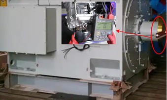
Fig. 1 was taken by the author on-site at a shipyard in October 2023. The illustration presents a detailed measurement scene of the motor connection part, and the shooting location is consistent with the main image. To present the relevant content more intuitively and clearly, the author used Photoshop software to stitch the images together.
Table 1Experimental parameter settings
Category | Parameter name | Value/description |
Driving motor system parameters | Motor type | Brushless DC motor |
Rated power | 60 kW | |
Rated torque | 10 N·m | |
Rotary inertia | 0.0014 kg·m2 | |
Rated speed | 800 r/min | |
Axial current limiting value | 20 A | |
Motor rotor flux linkage | 0.045 Wb | |
Motor pole logarithm | 6 | |
Nonsingular sliding mode controller parameters | Nonsingular sliding mode controller parameter 1 | 8 |
Nonsingular sliding mode controller parameter 2 | 2000 | |
Speed controller parameter 1 | 1.5×10⁻⁴ | |
Speed controller parameter 2 | 2.5×10⁻⁴ | |
Speed controller parameter 3 | 2.0 | |
Speed controller parameter 4 | 5×10⁶ | |
Speed controller parameter 5 | 30×104 | |
Improved parameters of quantum particle swarm optimization algorithm | Particle number | 40 |
Particle dimension | 2 | |
Maximum number of iterations | 50 times | |
Equal ratio coefficient | 0.8 | |
Fitness function | ITAE index |
In this paper, according to the torque value of the drive motor observed by the disturbance observer, whether it vibrates or not is judged, and then sliding mode control is carried out. Therefore, the observation result of the torque of the drive motor by the disturbance observer directly affects the final motor vibration control result. The proposed method is now used to measure the torque of the driving motor over a period of time. Fig. 2 shows the comparison between the observed value and the actual value of the motor torque.
Fig. 2Torque observation results
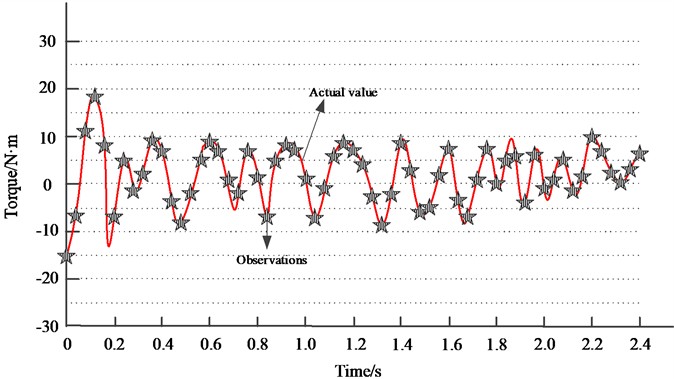
As shown in Fig. 2, the torque exceeded the rated value during the first 0.2 s of observation and returned to within 10 N·m after 0.2 s, indicating that vibration occurred during this period. The observed torque curve from the proposed method closely matches the actual torque curve, demonstrating that the disturbance observer achieves high observation accuracy.
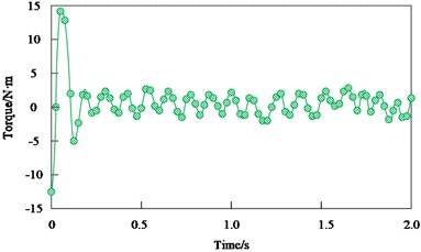
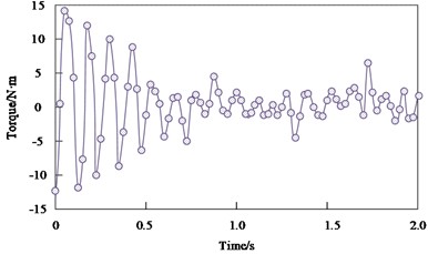
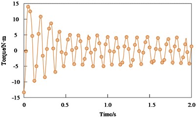
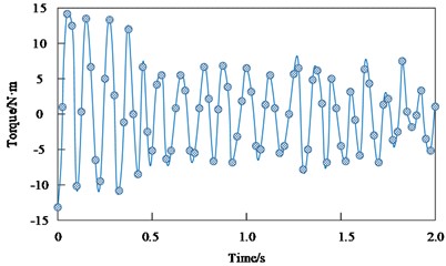
When vibration occurs, motor torque oscillates and its fluctuation amplitude increases. In contrast, under normal operation, torque changes smoothly with small fluctuations. Therefore, the effectiveness of vibration control can be evaluated by examining the torque response of the driving motor. At present, the method in this paper, the resonance controller method, the boundary disturbance analysis method and the repetitive controller method are used to control the driving motor, and the torque of the driving motor of the ship’s rim propulsion device changes with time in different control methods, as shown in Fig. 3.
Fig. 3Torque response: a) proposed method; b) resonant controller method; c) boundary perturbation analysis method; d) repetitive controller method
a)
b)
c)
d)
Through the analysis of Fig. 3, it can be observed that when the driving motor of the ship’s rim propulsion device vibrates, its actual torque far exceeds the rated torque by 10 N·m. Comparing the changes of motor torque in the control process of the four methods, the proposed method can control the torque within the rated torque in the shortest time, and the subsequent torque change amplitude is the smallest and tends to be stable. Although the driving motor of the ship's rim propulsion device controlled by the resonance controller method can also be within the rated torque, However, the torque does not tend to be stable, and the torque fluctuation amplitude of the driving motor of the ship rim propulsion device controlled by the boundary disturbance analysis method and the repetitive controller method is still large. Therefore, the proposed method has good response speed and control effect on the torque of the driving motor of the ship’s rim propulsion device, mainly due to the fact that the improved QPSO is utilized to optimize the parameters of the non singular sliding mode controller, so as to ensure that the nonsingular sliding mode controller can achieve the highest motor vibration control effect in the shortest time.
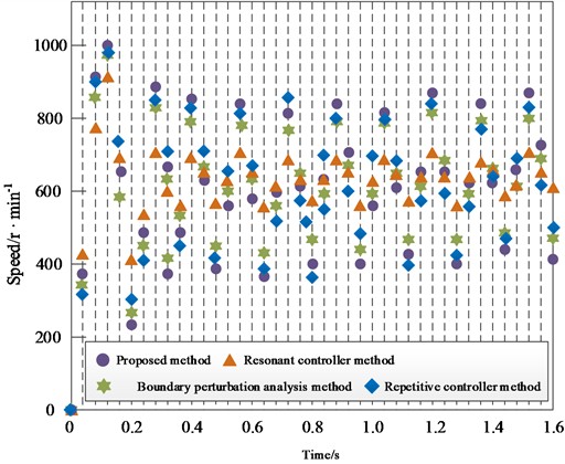
When the driving motor of the ship's rim propulsion device vibrates, the speed value of the driving motor will fluctuate rapidly, and the speed stability will decrease rapidly. However, when the driving motor of the ship’s rim propulsion device runs normally, its speed value will be stable in a certain range. Therefore, the control effect of motor vibration can be compared according to the speed fluctuation of the driving motor of the ship's rim propulsion device. To further and more comprehensively compare the vibration control effects, the speed variations of the driving motor under the proposed method, resonance controller method, boundary disturbance analysis method, and repetitive controller method were monitored. The speed responses over time for these four methods are shown in Fig. 4. From Fig. 4, it can be found that the initial rotational speed of the driving motor of the ship's rim propulsion device is far beyond its rated rotational speed due to vibration. After using the methods in this paper, resonance controller method, boundary disturbance analysis method and repetitive controller method, the rotational speed fluctuation amplitude of the driving motor of the ship's rim propulsion device is reduced, indicating that the above four methods can control the rotational speed of the driving motor of the ship’s rim propulsion device to varying degrees. However, the speed control effect of the proposed method is the best, which can make the speed of the driving motor respond quickly and finally stabilize between 500 r/min and 800 r/min. The fluctuation amplitude of the motor speed controlled by the other three methods is still relatively large compared with the proposed method. Therefore, the proposed method ensures that the driving motor can respond quickly when the ship needs to adjust its course or speed by precisely controlling the speed of the driving motor, thus enhancing the maneuverability and response speed of the ship, optimizing the propulsion efficiency of the ship, reducing unnecessary energy consumption and reducing operating costs.
Fig. 4Speed response
7. Conclusions
To address the issues such as low propulsion efficiency, wear and fatigue of marine mechanical components, and shortened equipment service life resulting from the vibration of the drive motor, it is essential to control the vibration of the drive motor in the marine rim propulsion device. Currently, the vibration control method for the drive motor of the marine flange propulsion device has problems including poor control over the torque and speed of the drive motor and a slow response speed. In order to tackle the above mentioned problems, a non singular sliding mode control method for the vibration of the driving motor of the marine flange propulsion device is proposed. This method measures the torque of the driving motor of the marine flange propulsion device through a disturbance observer to detect the motor vibration. Non singular sliding mode controller is used to control the motor, and the vibration control performance of the controller is improved based on improved QPSO. The results verify that the proposed method achieves higher torque observation accuracy and effectively improves torque and speed control during vibration. This provides data support for future ship fault detection and enhances the reliability and safety of ship systems, which is of great significance for improving overall ship performance and competitiveness.
Although the method proposed in this article has achieved significant results in driving motor vibration control, there are still some directions worth further exploration. Firstly, a more accurate coupled model of multiple physical fields can be studied in depth, and the model prediction information can be integrated into the disturbance observer to achieve a leap from passive monitoring to active prediction. Secondly, explore more efficient online self-tuning algorithms for controller parameters to cope with time-varying motor parameters and uncertainties under extreme sea conditions, further enhancing the adaptive capability of the control system. Finally, future research will combine vibration control with efficiency optimization of propulsion devices, exploring how to balance the overall propulsion efficiency of ships while suppressing vibration, and achieve multi-objective collaborative optimal control. In addition, combining digital twin technology to build a virtual mirror system for driving motors for real-time simulation and health management of vibration states is also an important direction for improving the intelligence level of ship propulsion systems in the future.
References
-
C. Xu, L. Fan, Z. Jiang, C. Shen, and H. Li, “Investigation on energy management strategy of gas-electric marine hybrid propulsion system with improved dynamic programing algorithm,” International Journal of Engine Research, Vol. 25, No. 1, pp. 140–155, Sep. 2023, https://doi.org/10.1177/14680874231195279
-
C. Yuan, D. Hou, and X. Liu, “Research on sliding mode control algorithm based on new power exponential reaching law,” (in Chinese), Computer Simulation, Vol. 41, No. 3, pp. 327–333, Dec. 2024, https://doi.org/10.3969/j.issn.1006-9348.2024.03.061
-
C. Ma, W. Xu, M. Liu, and J. Hong, “Low vibration control scheme for permanent magnet motor based on resonance controllers,” Energies, Vol. 17, No. 18, p. 4666, Sep. 2024, https://doi.org/10.3390/en17184666
-
L. Tang, R. Sun, and S. Zhang, “Boundary vibration constraint control design of motor-driven industrial moving belt systems subject to actuator input saturation,” IEEE Transactions on Consumer Electronics, Vol. 69, No. 2, pp. 140–147, May 2023, https://doi.org/10.1109/tce.2022.3218063
-
W. Zhao, B. Lu, Z. Liu, and G. Zhang, “An improved passivity-based control for suppressing the traction motor torque ripples due to traction network voltage fluctuation in high-speed railways,” IET Power Electronics, Vol. 16, No. 14, pp. 2287–2300, Dec. 2023, https://doi.org/10.1049/pel2.12549
-
Z. Zhang and P. Yan, “Robust composite repetitive control with disturbance observer for high-precision tracking of piezo-actuated nano-stages with measurement delays,” Review of Scientific Instruments, Vol. 94, No. 6, pp. 065001–1-65001-9, Jun. 2023, https://doi.org/10.1063/5.0145677
-
A. Kumar N, P. S. Kumar, M. K. Mohiddin, M. T. Gemeda, and A. Mishra, “GPS receiver position estimation and DOP analysis using a new form of the observation matrix approximations,” Journal of Sensors, Vol. 2022, pp. 1–12, Sep. 2022, https://doi.org/10.1155/2022/6772077
-
Y. Mei, D. Luo, K. Gong, and Y. Liao, “Disturbance observer-based event-triggered fault tolerant control for coupled spacecraft on SE(3) with actuator saturation and misalignment,” Nonlinear Dynamics, Vol. 111, No. 19, pp. 17987–18011, Nov. 2023, https://doi.org/10.1007/s11071-023-08751-w
-
F. Zeng, X. Ren, and Q. Wu, “A fault diagnosis method for motor vibration signals incorporating Swin transformer with locally sensitive hash attention,” Measurement Science and Technology, Vol. 35, No. 4, pp. 046121–46121, Apr. 2024, https://doi.org/10.1088/1361-6501/ad1cc4
-
K. A. Alattas et al., “Adaptive nonsingular terminal sliding mode control for performance improvement of perturbed nonlinear systems,” Mathematics, Vol. 10, No. 7, p. 1064, Mar. 2022, https://doi.org/10.3390/math10071064
-
M. Labbadi, M. Djemai, and S. Boubaker, “A novel non-singular terminal sliding mode control combined with integral sliding surface for perturbed quadrotor,” Proceedings of the Institution of Mechanical Engineers, Part I: Journal of Systems and Control Engineering, Vol. 236, No. 5, pp. 999–1009, Dec. 2021, https://doi.org/10.1177/09596518211064791
-
A. Din, Y. Sabbar, and P. Wu, “A novel stochastic Hepatitis B virus epidemic model with second-order multiplicative α-stable noise and real data,” (in Chinese), Acta Mathematica Scientia, Vol. 44, No. 2, pp. 752–788, Jan. 2024, https://doi.org/10.1007/s10473-024-0220-1
-
F. J. Gonzalez, “System identification based on characteristic curves: a mathematical connection between power series and Fourier analysis for first-order nonlinear systems,” Nonlinear Dynamics, Vol. 112, No. 18, pp. 16167–16197, Jul. 2024, https://doi.org/10.1007/s11071-024-09890-4
-
K. Engel, “An identity theorem for the Fourier-Laplace transform of polytopes on nonzero complex multiples of rationally parameterizable hypersurfaces,” Discrete and Computational Geometry, Vol. 69, No. 1, pp. 209–231, Dec. 2022, https://doi.org/10.1007/s00454-022-00467-9
-
M. C. D. B. Cardinali, J. H. Miranda, and T. B. Moraes, “Inverse Laplace transform to fit soil water retention curve and estimate the pore size distribution,” Soil and Tillage Research, Vol. 244, p. 106258, Dec. 2024, https://doi.org/10.1016/j.still.2024.106258
-
G. Long et al., “Interior-point-method-based switching angle computation for selective harmonic elimination in high-frequency cascaded H-bridge multilevel inverters,” Journal of Power Electronics, Vol. 24, No. 8, pp. 1229–1240, Mar. 2024, https://doi.org/10.1007/s43236-024-00793-6
-
P. Vavruska, F. Bartos, M. Stejskal, M. Pesice, P. Zeman, and P. Heinrich, “Increasing tool life and machining performance by dynamic spindle speed control along toolpaths for milling complex shape parts,” Journal of Manufacturing Processes, Vol. 99, pp. 283–297, Aug. 2023, https://doi.org/10.1016/j.jmapro.2023.04.058
-
D. Pasqualotto, S. Rigon, and M. Zigliotto, “Sensorless speed control of synchronous reluctance motor drives based on extended Kalman filter and neural magnetic model,” IEEE Transactions on Industrial Electronics, Vol. 70, No. 2, pp. 1321–1330, Feb. 2023, https://doi.org/10.1109/tie.2022.3159962
-
J. Nayak, H. Swapnarekha, B. Naik, G. Dhiman, and S. Vimal, “25 years of particle swarm optimization: Flourishing voyage of two decades,” Archives of Computational Methods in Engineering, Vol. 30, No. 3, pp. 1663–1725, Dec. 2022, https://doi.org/10.1007/s11831-022-09849-x
-
F. M. Fernández, “Variational approach to the Schrödinger equation with a delta-function potential,” European Journal of Physics, Vol. 43, No. 2, p. 025401, Mar. 2022, https://doi.org/10.1088/1361-6404/ac3f27
-
L. Abualigah, “Particle swarm optimization: advances, applications, and experimental insights,” Computers, Materials, and Continua, Vol. 82, No. 2, pp. 1539–1592, Jan. 2025, https://doi.org/10.32604/cmc.2025.060765
-
V. Kartal, M. E. Emiroglu, O. M. Katipoglu, and E. Karakoyun, “Prediction of scour hole characteristics caused by water jets using metaheuristic artificial bee colony-optimized neural network and pre-processing techniques,” Journal of Hydroinformatics, Vol. 25, No. 6, pp. 2427–2443, Nov. 2023, https://doi.org/10.2166/hydro.2023.230
-
A. Dixit, A. Mani, and R. Bansal, “An adaptive mutation strategy for differential evolution algorithm based on particle swarm optimization,” Evolutionary Intelligence, Vol. 15, No. 3, pp. 1571–1585, Feb. 2021, https://doi.org/10.1007/s12065-021-00568-z
-
A. Kadu and A. Khandekar, “Optimized decentralized PID controller for TITO systems using grey wolf optimization with experimental application,” Engineering Research Express, Vol. 7, No. 4, p. 045416, Dec. 2025, https://doi.org/10.1088/2631-8695/ae192b
About this article

The authors have not disclosed any funding.
The datasets generated during and/or analyzed during the current study are available from the corresponding author on reasonable request.
Lijun Han: conceptualization, methodology, software, formal analysis, investigation, data curation, writing-original draft. Qian Jiang: methodology, software, validation, investigation, visualization.
The authors declare that they have no conflict of interest.

