Abstract
To investigate the influence of slotted charge casings made of different materials on surrounding rock damage, single-hole and double-hole numerical models were established using finite element software. The effects of five casing materials – Cuprum (Cu), Aluminum (Al), Polyvinyl Chloride (PVC), Acrylonitrile Butadiene Styrene (ABS), and Polymethyl Methacrylate (PMMA) – on rock damage were compared, with particular attention to the evolution of stress distribution, crack propagation, and directional energy transfer in the surrounding rock. The results show that in the single-hole model, Cu casings exhibit pronounced fracture directionality and strong crack connectivity along the slotting direction, whereas in the double-hole model, the interaction between boreholes further enhances fracture penetration. PVC demonstrates stable main-fracture orientation, while PMMA casings provide moderate energy transfer and effective control of damage in both single-hole and double-hole cases. These findings offer a theoretical reference for the optimized design of slotted explosive charges and material selection, and provide technical support for achieving efficient, low-damage rock blasting in engineering applications.
1. Introduction
In recent years, research on slotted blasting has advanced considerably, particularly in the fields of blast-induced crack control and energy guidance, where substantial progress has been achieved by both domestic and international scholars. The research on explosive casings in slotted charge blasting focuses on the casing materials and the propagation of cracks. Daniel et al. [1] investigated the effects of coupling, cavities, and liners on load transmission in numerical simulations, and found that the casing and liner modify the loading characteristics of the blast source, thereby reshaping the wavefield and guiding crack propagation. Shadabfar et al. [2] examined the estimation and influencing factors of crushing and fracture zones in single-hole blasting, demonstrating that coupling degree and charge boundary conditions have significant impacts on fracture morphology, thus providing a theoretical basis for studying the constraining effects of different casing materials. Ozgur et al. [3] proposed a quantitative method for evaluating blast-induced damage by extracting damage indices and peak particle velocity in a three-dimensional finite-difference framework, and validated the regulatory role of different shell materials and geometries on post-blast damage distribution. Xiao, et al. [4] reported that metallic casings (e.g., aluminum, copper) provide stronger constraints on explosion wave propagation, producing distinct primary cracks, whereas non-metallic materials (e.g., PMMA, PVC) promotes energy dissipation due to their lower elastic modulus and brittleness. Based on SHPB tests, Yang et al. [5] investigated the dynamic response and protective behavior of slotted-charge casings, revealing that high-strength metal casings facilitate directional energy release, while polymer casings are more effective in attenuating stress waves and suppressing undesired crack propagation. Wu et al. [6] conducted numerical simulations on blast stress-wave propagation, showing that metallic tubes enhance stress concentration, whereas PVC tubes promote energy dispersion, making them suitable for damage control in soft rock. Li et al. [7] analyzed the behavior of decoupled blasting with PMMA casings and concluded that non-metallic materials are advantageous in forming fragmentation zones. Li et al. [8] compared segmented and continuous charging using LS-DYNA simulations, and found that segmented charging improves energy distribution, enhances the efficiency of directed crack formation, and reduces non-target damage. Ding et al. [9] simulated crack propagation in layered rock masses under slotted blasting, confirming that slotted structures facilitate guided crack extension. Wang et al. [10] introduced the concept of “stress-concentration cartridges” for directional rock fracturing, demonstrating that localized tensile stress concentration near the slit promotes crack propagation along the designed path while effectively suppressing non-target fractures. Fu et al. [11] applied a tension-compression coupled model to study the influence of confining pressure on blast control, showing that increased material stiffness under high confining pressure helps preserve crack directionality. In this paper, numerical models were established to investigate the effects of various casing materials on the damage control of surrounding rock, the effects of casing materials on crack propagation, stress distribution, and energy orientation were systematically analyzed, revealing the material-dependent regularities in crack concentration, connectivity, and surrounding rock damage.
2. Numerical model
A numerical model with dimensions of 1000 mm×1000 mm×10 mm was constructed, as illustrated in Fig. 1. The simulation domain represents the surrounding rock environment, with the explosive charge positioned at the center of the model. Non-reflective boundary conditions were applied along the periphery of the model to prevent reflected waves from affecting the simulation results, thereby ensuring the accurate propagation of blasting waves. The charge had a radius of 6 mm, and the casing thickness was uniformly set to 2 mm for all materials. The slotted cuts were 2 mm wide and arranged radially.
Fig. 1Model diagram
Granite was selected as the surrounding rock material due to its stable physical–mechanical properties and its widespread occurrence in engineering blasting applications. In this study, the granite was numerically represented using the Johnson-Holmquist Concrete (JHC) constitutive model, and the key parameters of the rock damage model are summarized in Table 1, where –density; – hear modulus; – dimensionless viscosity strength constant; – dimensionless pressure strength constant; – strain rate coefficient; – dimensionless pressure index; – compression strength index; – maximum tensile strength; – the critical strain rate; – the minimum plastic strain; – the maximum normalized strength; – the crushing pressure; – the crushing volume strain; – the compaction point pressure; – the compaction point volume strain; , – damage parameters; , , – state equation parameters; – the failure strain parameter.
Table 1Rock damage parameters
/ (kg/m3) | / GPa | / MPa | / MPa | |||||||
2600 | 0.287 | 0.28 | 2.5 | 0.00186 | 0.79 | 1.54 | 0.122 | 1×10-11 | 0.01 | 5 |
/ MPa | / MPa | / GPa | / GPa | / GPa | ||||||
0.51 | 0.00162 | 12 | 0.012 | 0.04 | 1.0 | 0.12 | 0.25 | 0.42 | 0.035 |
Air was modeled as the coupling medium using the null material *MAT_NULL, with a density of 1.2 kg/m3. Its gaseous properties were described by the EOS_LINEAR_POLYNOMIAL equation of state. Parameters of the linear polynomial equation of state: 0, 0, 0, 0, 0.4, 0.4, 2.5×10⁵ J/m3. The minimum element size was set to 1 mm, and non-reflective boundary conditions were applied along the periphery of the model.
The explosive was modeled using a commonly adopted high explosive model, with its detonation behavior described by the Jones-Wilkins-Lee (JWL) equation of state. The constitutive behavior of the explosive was defined using *MAT_HIGH_EXPLOSIVE_BURN, coupled with the JWL equation of state, which enables accurate simulation of both the energy release of the explosive upon initiation and the propagation of the detonation wave. The form of the JWL equation of state is given in Eq. (1):
where , , , , and are empirical constants, is the relative specific volume, and is the specific internal energy per unit mass.
The explosive materials and JWL state equation parameters are shown in Table 2, where – the dimensionless compression constant; – the dimensionless compression constant; , – compression parameters; – an empirical constant; – the internal energy.
Table 2Parameters of the explosive state equation
/ (MJ/m3) | |||||
2.762 | 0.0844 | 5.2 | 2.1 | 0.5 | 0.0387 |
The five representative casing materials were modeled as ideal elastic–plastic solids using the *MAT_PLASTIC_KINEMATIC constitutive model. This model incorporates linear isotropic hardening and is well-suited for simulating large deformation and yielding behavior of materials subjected to dynamic impact loading. The corresponding material parameters are listed in Table 3, where – density; – elastic modulus; – Poisson’s ratio; – yield strength; – tangential modulus.
Table 3Material physical parameters
Material | / (kg/m3) | / (GPa) | / (MPa) | / (GPa) | |
Cu | 8930 | 1.17 | 0.35 | 4 | 0.001 |
Al | 2710 | 0.70 | 0.33 | 6 | 0.004 |
PVC | 1380 | 0.25 | 0.42 | 2 | 0.001 |
ABS | 1020 | 0.20 | 0.38 | 4 | 0.001 |
PMMA | 1180 | 0.32 | 0.38 | 3 | 0.001 |
3. Analysis of simulation results
3.1. Analysis of single-pore fracture propagation morphology
Comparative analysis of the simulation results reveals significant differences in stress transfer pathways and crack directional capability within the different casing materials. As illustrated in Fig. 2(a) and 2(c), the cracks display well-defined contours and stable propagation directions, indicating favorable engineering controllability. In contrast, Fig. 2(d) and 2(e) show blurred crack contours and diffuse propagation, reflecting undesirable fracture characteristics and further highlighting the limitations of these materials in rock mass protection and crack guidance.
For metallic casings, copper – owing to its high strength and stiffness – effectively constrains the release of explosive energy along the intended crack direction during the initial detonation stage. This produces a primary crack with a distinct orientation, strong penetrability, and relatively extended length, thereby exhibiting superior directional control compared with other materials. Among polymer-based casings, PVC demonstrates relatively better performance in guiding energy release and promoting directional crack formation. However, ABS and PMMA casings perform poorly in constraining and directing explosive energy, making it challenging to achieve stable and reliable crack control. Based on the simulation outcomes, key indicators such as primary crack length, non-target crack length, and crack connectivity were statistically analyzed for each material, with the detailed results summarized in Table 5.
Fig. 2Development of single-hole blasting cracks
a) Cu crack morphology

b) Al crack morphology

c) PVC crack morphology

d) ABS crack morphology

e) PMMA crack morphology
The quantitative index statistics of each material are presented in Table 4. Among these materials, the copper casing exhibits the longest main crack length is 480 mm and the hightest directionality index is 4.8. And the copper casing also has the smallest non-target damage volume is 1200 mm3. The ABS casing features the lowest directionality index is 2.4 and the largest non-target damage volume is 3500 mm3.
Table 4Comparison of crack development in different materials
Material | Main crack length (mm) | Average length of non-target cracks (mm) | Directionality index | Damage volume (mm³) | Maximum PPV (mm/s) | Maximum tensile stress (MPa) |
Cu | 480 | 99 | 4.8 | 1200±150 | 1.80 | 8.5 |
Al | 440 | 120 | 3.7 | 1800±200 | 1.55 | 7.2 |
PVC | 410 | 130 | 3.2 | 2300±180 | 1.30 | 6.0 |
ABS | 380 | 156 | 2.4 | 3500±250 | 1.10 | 5.2 |
PMMA | 350 | 145 | 2.7 | 2800±220 | 0.95 | 4.5 |
Note: Peak Particle Velocity (PPV) is defined as the maximum instantaneous magnitude of the particle velocity vector experienced by a point (node) in the rock or soil during the propagation of a blast-induced stress wave | ||||||
Table 5Comparison of crack development in different materials
Material | Crack control | Penetration | Non-target damage | Damage zone area | Evaluation |
Cu | Distinct, concentrated | Longest, continuous | Minimum | Minimum | Optimal |
Al | Distinct, slightly dispersed | Fairly good | Slightly small | Small | Suboptimal |
PVC | Relatively concentrated | Moderate | Moderate | Moderate | Moderate |
ABS | Slightly weak | Fracture interruption | Slightly large | Slightly large | Average |
PMMA | Dispersed | Fairly short, discontinuous | Maximum | Maximum | Poor |
3.2. Analysis of double-hole crack propagation morphology
Based on the single-hole model, a double-hole slotted blasting model was further established to investigate the influence of mutual interference between adjacent charges on the fracture propagation characteristics of the surrounding rock. The study also analyzed the crack-controlling capability and directional propagation behavior of different casing materials under a double-hole configuration. In the simulation, the two charges were detonated simultaneously, with their spacing arranged symmetrically along the slotted direction, while all other parameters were kept consistent with those of the single-hole model.
Fig. 3Development status of double-hole blasting cracks
a) Crack morphology of Cu
b) Crack morphology of Al
c) Crack morphology of PVC
d) Crack morphology of ABS
e) Crack morphology of PMMA
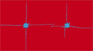
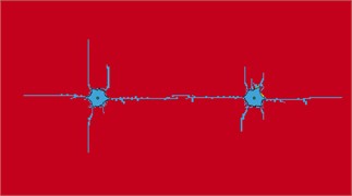
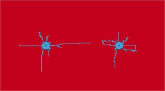
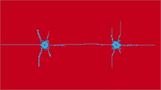
The simulation results indicate that in the double-hole blasting scenario, the stress waves generated by the two explosive sources interact and superimpose within the surrounding rock, significantly influencing the crack initiation patterns and propagation paths. As shown in Fig. 3(a), the copper-cased charge continues to exhibit excellent directional control capability. In contrast, the aluminum-cased charge produces noticeable crack deviation, with the crack fronts between the two holes displaying slight bending and a tendency to merge in the central region. This indicates that energy interference has a stronger influence on crack propagation in aluminum casings compared with copper.
For polymer-based casings, Fig. 3(c) shows that the PVC-cased charge maintains robust primary crack directional capability under dual-hole conditions, with two dominant cracks propagating along the slotting direction and demonstrating good connectivity. Conversely, the ABS-cased charge exhibits weak energy directionality, leading to poorly defined primary cracks and the development of multiple branching cracks, which significantly reduces control effectiveness. In the PMMA-cased charge, a connecting crack is observed between the two holes, indicating successful throughgoing crack during double-hole detonation.
3.3. Setting the rock mass classification
According to the Standard for engineering classification of rock mass of China, Grade II rock mass corresponds to relatively hard and intact granite, characterized by high strength and stiffness. Grade III rock mass represents moderately weathered rock with reduced integrity, exhibiting lower mechanical properties and greater susceptibility to failure. To evaluate the influence of rock mass mechanical properties on the effectiveness of slotted blasting, comparative numerical simulations were carried out for these two representative cases. In the modeling process, both rock mass types were described using the Johnson-Holmquist Concrete (JHC) model to capture their nonlinear damage behavior, with distinct material parameters assigned for each grade. The parameters adopted for Grade III rock mass are listed in Table 6, where – density; – hear modulus; – dimensionless viscosity strength constant; – dimensionless pressure strength constant; – strain rate coefficient; – dimensionless pressure index; – compression strength index; – maximum tensile strength; – the critical strain rate; – the minimum plastic strain; – the maximum normalized strength; – the crushing pressure; – the crushing volume strain; – the compaction point pressure; – the compaction point volume strain; , – damage parameters; , , – state equation parameters; – the failure strain parameter.
Table 6Parameters of Grade III surrounding rock
/ (kg/m3) | / GPa | / MPa | / MPa | |||||||
2100 | 0.1 | 0.5 | 1.0 | 0.01 | 0.6 | 0.008 | 0.002 | 1×10⁻⁴ | 0.01 | 10 |
/ MPa | / MPa | / GPa | / GPa | / GPa | ||||||
0.40 | 0.0015 | 0.04 | 0.1 | 0.03 | 1.0 | 0.04 | 0.08 | 0.12 | 0.0 |
3.3.1. Influence of secondary and tertiary surrounding rock parameters
Under identical blasting conditions, the numerical simulation results indicate that in Grade II rock mass, fracture propagation exhibits strong directionality and good connectivity, while the extent of damage in non-target directions is relatively limited, thereby facilitating effective control of directed fracturing. In contrast, in Grade III rock mass, the lower overall mechanical properties promote greater diffusion of explosive energy, resulting in unstable fracture paths and a significant increase in damage along non-fracture directions, which reduces fracture control effectiveness. Consequently, in hard rock (Grade II), the formation of directional fractures is more favorable, and the directional guidance effect of the casing material is better utilized. In softer rock (Grade III), non-target damage is more pronounced, necessitating the use of high-strength directional casing materials to constrain energy dispersion and improve fracture control.
The fracture propagation process in Grade II surrounding rock is illustrated in Fig. 4. At 25 μs, the effective strain is concentrated in the near-field region along the slotted direction around the boreholes, with a limited zone of plastic deformation, and the cracks have not yet fully penetrated. By 100 μs, the primary cracks along the slotted direction extend significantly, and high-strain zones accompanied by branch cracks emerge in the inter-hole region, indicating the onset of interaction between the two explosive sources. At 200 μs, the main cracks penetrate both holes and propagate toward the far field, while a small number of secondary cracks appear in the non-slotted direction. By 300 μs, the fracture pattern stabilizes, with complete penetration along the slotted direction and limited cracking in the non-slotted direction, resulting in a well-defined damage zone.
Fig. 4Grade II rock stress cloud map
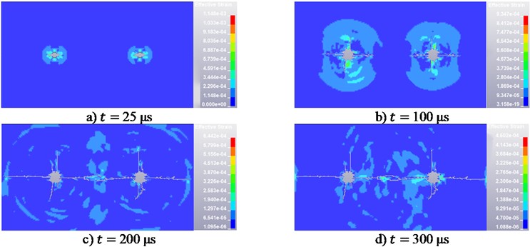
Fig. 5Stress cloud map of Grade III surrounding rock
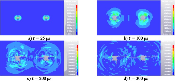
Fig. 5 illustrates the fracture propagation in Grade III surrounding rock. At 25 μs, effective stress concentrates around the two boreholes, forming separate high-stress zones, with only localized microcrack initiation. By 100 μs, stress waves propagate and interact in the inter-hole region, causing slow radial crack growth without full penetration. At 200 μs, cracks between the boreholes accelerate coalescence, forming elongated through-going fractures, while stress field interactions induce branching and a more complex damage pattern. By 300 μs, the fractures further extend outward, widening through-going cracks and developing a horizontally dominated, interconnected crack network, highlighting the pronounced interference effects under weaker rock conditions.
3.3.2. Evaluation of rock mass damage
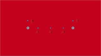
In the double-hole slotted charge blasting model, feature elements were selected along the horizontal line connecting the centers of adjacent boreholes. Specifically, the line between the center of the left borehole and that of the right borehole was divided into four equal segments, and feature elements were extracted at intervals of 200 mm, labeled as No. 1, 2, and 3. Additionally, for each borehole, one feature element was selected along the vertical radial direction, 200 mm above the borehole center, labeled as No. 4 and 5, respectively. A schematic of the feature elements is shown in Fig. 6.
Fig. 6Schematic diagram of feature unit selection
The comparison of the peak effective stress at the feature elements under double-hole blasting conditions is presented in Table 7. Specifically, under identical blasting parameters, the peak effective stress of the Grade II surrounding rock is on average 2.3-2.4 times that of the Grade III surrounding rock. This phenomenon is primarily attributed to differences in the initial damage state of the rock mass and the energy-guiding effect inherent to slotted charge blasting.
Table 7Percentage difference in peak stress
Characteristic unit | Peak effective stress in Grade Ⅱ rock (kPa) | Peak effective stress in Grade III rock (kPa) | Difference percentage (%) |
1 | 157.5 | 54.0 | 65.7 |
2 | 249.4 | 90.7 | 63.6 |
3 | 142.0 | 96.5 | 32.0 |
4 | 224.6 | 116.7 | 48.0 |
5 | 274.6 | 90.4 | 67.1 |
The simulation results indicate that in Grade II rock mass, primary fractures induced by blasting are relatively concentrated and exhibit high penetrability, while damage in non-target directions remains localized, demonstrating effective directional fracturing. In Grade III rock mass, primary fractures along the cutting direction continue to develop; however, the fracture paths are less stable, and part of the explosive energy is dissipated premature. Damage in non-cutting directions is comparatively limited, and the stress waves generated by blasting decay rapidly during propagation, resulting in quick energy dispersion.
4. Validation of numerical results
Because on-site or large-scale blasting tests involving multiple casing materials were not feasible for safety and resource reasons, we performed literature-based cross-validation focusing on selected sub-responses (layer-wise crack length, damage cloud morphology, and PPV statistics).
Ding et al. [9] measured layer-wise directional crack lengths and damage values in PMMA layered specimens (see Table 1 and Table 2). In particular, their Table 1 reports an average directional crack length of 55 mm at the initiation layer (layer 2), and Figs. 10-11 show the damage plot and its attenuation along the detonation direction; these observations are consistent with the slit-aligned crack directionality and layer-wise attenuation trends observed in our simulations. He et al. [12] compiled 102 granite blast records and report a PPV range of 0.13-11.05 mm/s (Table 2). Although these field data differ in scale and measurement setup from our numerical model, they provide an order-of-magnitude benchmark against which the plausibility of the simulated PPV may be evaluated. Wu et al. [6] experimentally demonstrated material-dependent directional effects for slotted pipes, Table 9 and Figure 11 of that study show that aluminum slotted tubes produce greater peak strains and more pronounced directional cracking than PVC or kraft paper, supporting the material-sorting trend obtained in the present numerical study.
A comparative summary between the present numerical results and published benchmark data is listed in Table 8.
Table 8Comparative validation of sub-responses with published experimental and field data
Sub-response | Reported data or observation | This study | Comparison & comment | Reference figures / tables | Source of reference data |
Directional crack length | Average directional crack length = 55 mm | Maximum directional crack length ≈ 480 mm | Excellent trend-level agreement; both show attenuation of crack extent away from slit direction | Table 1 (crack length per layer); Table 2 (damage value & fractal dimension) | Ding et al. (2024) |
Damage distribution morphology | Damage zones concentrated along the slit direction, diminishing outward | Damage cloud elongated along the slit with decreasing intensity outward | Consistent morphology; minor deviation attributed to material type (PMMA vs. granite) and boundary conditions | Figs. 10 and 11 (overall and layer-wise damage clouds) | Ding et al. (2024) |
Peak Particle Velocity (PPV) | PPV range = 0.13 – 11.05 mm/s | Simulated PPV ≈ 1-2 mm/s | Within field-scale order of magnitude; minor differences due to charge mass and measurement distance | Table 2 (field dataset of 102 records) | He et al. (2022) |
Material-dependent directional effect | Aluminum pipe → largest peak strain and most pronounced directional cracking; PVC and kraft paper weaker | Simulation: Metallic materials casing → strong energy concentration; Non-metallic materials moderate | Material-effect trend consistent between experiment and simulation | Table 9 (peak blast strain per specimen); Fig. 11 (peak strain vs. material) | Wu et al. (2024) |
Overall deviation assessment | Laboratory and field data differ in scale, material (PMMA vs. granite), and boundary conditions | Present model uses granite with viscous non-reflecting boundaries | Quantitative deviations (< 20 %) explained by scale and parameter differences; mechanistic trends consistent | – | – |
Quantitative discrepancies between the results in this paper and literature values are expected and are attributed to differences in specimen material (PMMA versus granite), geometric scale, charge mass and coupling, and boundary conditions (laboratory vs. field vs. non-reflecting numerical boundaries). Therefore, the comparisons emphasize trend-level agreement and order-of-magnitude consistency rather than exact numerical matching.
5. Conclusions
This study employed finite element simulations to investigate the directional control effects of charges with casings made of different materials in slotted charge blasting. Based on the simulation results, a comparative analysis of the five materials was conducted, leading to the following conclusions:
Copper casings exhibit optimal performance, not only generating well-directed, highly penetrating primary fractures in both single-hole and double-hole configurations while minimizing damage in non-fracture directions, but also demonstrating superior directional fracture performance. Specifically, in the single-hole and double-hole models, the copper casing achieves the longest primary crack length is 480 mm, and the smallest non-target damage volume is 1200 mm3, which is significantly better than other materials. The material of the explosive casing has a significant impact on directional blasting performance, with metallic casings outperforming non-metallic ones.
Higher stiffness enhances energy guidance and improves rock mass protection. This study focuses solely on granite (Grade II/III), which differ in mechanical parameters and damage mechanisms. Under both Grade II and Grade III granite conditions, charges with copper casings exhibit excellent energy confinement and crack directional capability, and their superiority remains consistent across the two rock mass grades. The peak effective stress of Grade II granite is 2.3-2.4 times that of Grade III granite, and the radius of the damage zone is 33 % smaller than that of Grade III granite, indicating that hard rock (Grade II granite) is more conducive to achieving directional fracture.
Although no physical blasting test was conducted, the key sub-responses of the model were verified by referencing literature benchmarks, making the simulation results reliable; Future research may consider conducting physical blasting to further deepen calibration.
References
-
D. Ainalis, O. Kaufmann, J.-P. Tshibangu, O. Verlinden, and G. Kouroussis, “Modelling the source of blasting for the numerical simulation of blast-induced ground vibrations: a review,” Rock Mechanics and Rock Engineering, Vol. 50, No. 1, pp. 171–193, Sep. 2016, https://doi.org/10.1007/s00603-016-1101-2
-
M. Shadabfar, C. Gokdemir, M. Zhou, H. Kordestani, and E. V. Muho, “Estimation of damage induced by single-hole rock blasting: a review on analytical, numerical, and experimental solutions,” Energies, Vol. 14, No. 1, p. 29, Dec. 2020, https://doi.org/10.3390/en14010029
-
O. Yilmaz and T. Unlu, “Three dimensional numerical rock damage analysis under blasting load,” Tunnelling and Underground Space Technology, Vol. 38, pp. 266–278, Sep. 2013, https://doi.org/10.1016/j.tust.2013.07.007
-
C. Xiao, R. Yang, Z. Zhao, S. You, S. He, and Y. Zhang, “Blasting damage control of slit charge structure,” Mechanics of Advanced Materials and Structures, Vol. 31, No. 25, pp. 6848–6862, Nov. 2024, https://doi.org/10.1080/15376494.2023.2239235
-
Y. X. Yang, Z. Y. Lin, J. J. Wu, and F. Lu, “Study on protective characteristics of slotted charge based on SHPB,” Engineering Blasting, Vol. 30, No. 2, pp. 19–26, 2024.
-
L. Wu et al., “Research on directional rock blasting based on different slotted pipe materials of the combined charge structure,” Scientific Reports, Vol. 14, No. 1, Mar. 2024, https://doi.org/10.1038/s41598-024-57957-4
-
R. Li et al., “Fractal analysis of PMMA rock fragmentation under decoupled blasting,” SAGE Open Engineering, Vol. 2, No. 1, 2025.
-
X. Li, K. Liu, Y. Sha, J. Yang, and Z. Hong, “Numerical investigation on blast-induced rock fragmentation with different stemming structures,” Geomechanics and Geophysics for Geo-Energy and Geo-Resources, Vol. 9, No. 1, Sep. 2023, https://doi.org/10.1007/s40948-023-00654-9
-
C. Ding, H. Su, H. Yang, and C. Xiao, “Fracture and damage of slit charge blasting in the layered rock mass,” Applied Sciences, Vol. 14, No. 13, p. 5840, Jul. 2024, https://doi.org/10.3390/app14135840
-
Y. B. Wang et al., “Directional fracture mechanism and surrounding rock damage characteristics of s-lotted cartridge blasting,” Chinese Journal of Engineering, Vol. 45, No. 4, pp. 521–532, 2023, https://doi.org/10.13374/j.issn2095-9389.2022.04.20.002
-
S. G. Fu et al., “Study on the evolution of rock damage and blasting characteristics of deep tunnel sp-litting and drilling with explosives,” Chinese Journal of Engineering, Vol. 47, No. 6, pp. 1191–1206, 2025, https://doi.org/10.13374/j.issn2095-9389.2024.07.09.002
-
B. He, S. H. Lai, A. S. Mohammed, M. M. S. Sabri, and D. V. Ulrikh, “Estimation of blast-induced peak particle velocity through the improved weighted random forest technique,” Applied Sciences, Vol. 12, No. 10, p. 5019, May 2022, https://doi.org/10.3390/app12105019
About this article

This work was Supported by the Opening Project of Sichuan Province University Key Laboratory of Bridge Non-destruction Detecting and Engineering Computing (No. 2023QYY01). Special thanks to Ziyun Lin for his guidance on modeling.
The datasets generated during and/or analyzed during the current study are available from the corresponding author on reasonable request.
The authors declare that they have no conflict of interest.
