Abstract
The construction of main pipelines is now predominantly carried out using high-strength steels. This makes it possible to increase pipeline capacity while maintaining the existing pipe geometry. However, the issue of ensuring the strength of such pipelines in the presence of surface defects is still relevant. This is especially true for pipeline segments that are located in hard-to-reach places, and therefore, it is difficult to repair and restore. At the same time, the introduction of high-strength steels involves a complex system of material alloying and special thermo-mechanical strengthening technologies. As a result, special structures of increased strength can be produced, but they are sensitive to reheating, in particular when welding technologies are used. This is due to the formation of a special zone of thermal deformation influence in the vicinity of the weld. Material properties of the pipes differ from their original characteristics. The stress-strain state is formed, which also affects the strength of the welded pipeline. The nature of the stress-strain state of welded joints of pipes made of high-strength materials differs from the well-studied stress distributions in pipelines built in the past sixty-eighty years of the past century. In particular, several localized maxima of stresses can be located not only on the weld axis but also in the zone of thermal deformation influence. Therefore, it is important to evaluate the effect of weld stresses in welded joints of high-strength steel pipes on the strength of the pipeline in the presence of surface defects. Since the defect may be located at an arbitrary distance from the weld axis, the predicted strength of the welded pipeline segment can vary significantly.
Highlights
- The study introduces an extended analytical model for plastic deformation that accurately describes residual stress distributions with peak values shifted from the weld axis into the heat-affected zone.
- A generalized two-parameter fracture assessment evaluates safety factors for surface defects at arbitrary distances from the weld axis, bridging operational loads and technological welding stresses.
- Tensile residual stresses in the heat-affected zone significantly reduce safety margins; axial defects in this region can reach critical levels (nr = 0.89) requiring repair or pressure reduction.
- Defects on the inner pipe surface are found to be more dangerous than those on the outer surface, consistently yielding lower safety factors due to the specific stress-strain state distribution.
1. Introduction
The use of high-strength steels for pipelines creates conditions for increasing amounts of transported hydrocarbons due to an increase in operating pressures. It is known [1, 2] that it is now possible to obtain significant pressures of transported products, which can range from 12 to 20 MPa. This also makes it possible to increase the distance between individual pumping stations. Such approaches are especially relevant nowadays when pipelines are laid across sea areas. In recent decades, the scope of developed offshore fields and, accordingly, pipelines has increased by more than 25 % [3]. However, such pipelines are constantly exposed to aggressive media. Therefore, it is important to continuously diagnose the technical state of repair of the main pipelines in order to identify defects and determine their operational strength. The existing results of diagnosing main pipelines by non-destructive methods show that the most typical are surface defects on the outside or inside of the pipe [4, 5]. The size of such defects can range from 20 % to 70 % of the nominal pipe wall thickness. At the same time, defects in the vicinity of welds are additionally affected by technological stresses because of the welding cycle [6]. Ring welds are particularly dangerous, as they are often made immediately at the construction site. This causes the risk of unpredictable external influences and increases the likelihood of surface defects in welded pipe joints. The latter factor is so important that work [1] points out the need to take into account the conditions of pipeline welding when developing new high-strength pipe steel grades. Such steels are characterized by an increased content of alloying elements that ensures a fine-grained structure and high strength of structural components [7]. In such a case, special new methods of controlled thermomechanical treatment are used, in particular the so-called TMCP process of material hardening followed by rapid cooling [1, 2, 8]. However, the homogeneity of such a material is disturbed by the thermal cycle of welding. This is due to local heating of the material to the melting point with the simultaneous occurrence of significant thermal deformations and recrystallization of the welded areas. The so-called zone of thermal deformation influence is formed, which differs in its characteristics from the weld metal and the base material [9, 10]. At the same time, recrystallization of the base material is often accompanied by low-temperature transformations. The latter are often diffusionless due to the rapidity of the welding process, which leads to the formation of microstructural (structural) stresses.
These structural stresses, in combination with temperature stresses, lead to the formation of a complicated stress-strain state in the welded joint. Such a stress-strain state is characterized by the emergence of maximal values in the most weakened part of the welded pipe joint – the zone of influence of thermal deformation, and slightly lower stress values are observed on the weld axis [6]. These factors are additional but permanent in welded pipeline structures. Various calculation and experimental methods are used to study such stresses. However, the experience of diagnosing structures of long-term operation shows that a combination of experimental and computational methods is advisable. In particular, papers [6, 11, 12] reveal the essence of such a method based on solving the inverse problem of a welded pipeline joint with its intrinsic residual deformations determined on the basis of experimental data. At the same time, the presence of surface defects in the vicinity of welds weakens the strength of the pipeline and affects its operational reliability. The issue of the influence of axial welding stresses on the strength of a welded joint of a pipeline that is made of high-strength steel was partially disclosed in [6]. In particular, the effect of compressive stresses on the outer surface of the welded joint, which contributes to the inhibition of defect opening, was studied. However, the paper does not show the effect of the defect location relative to the weld axis. It is also advisable to consider the effect of annular stresses, which are higher than axial stresses. These stresses are tensile on both the inner and outer surfaces of the pipe. In this case, setting the strength depending on the pipe surface would also have an impact on the static strength of the pipeline.
2. Literature review
To study the static strength of pipelines containing pipe material defects, the brittle-ductile fracture criterion is widely used, which is denoted in the special literature as the two-parameter criterion R6 [13, 14]. This approach makes it possible to take into account the size of the defect under consideration, operational loads on the pipeline, characteristics of the base material, geometric dimensions of the pipeline, etc. At the same time, papers [12, 15, 16] developed the aforesaid methodology and showed an approach for the complex consideration of operational and technological (welding) stresses in the vicinity of the defect. However, given the characteristics of low-alloy pipe steels discussed in [15, 16], the main focus is on the strength of the pipeline when the defect is located on the weld axis. There, the welding stresses reached their maximum and were the most dangerous. Similarly, papers [17, 18] show the operating conditions of a main pipeline in the presence of global bending stresses in the above-ground segments of main pipelines. There, defects on the weld axis were also considered, where the total effect of all components of the stress state was maximum.
The analysis of literature data [6, 19-21] shows that under certain conditions, the maximum stress values can be shifted by a certain distance relative to the weld axis into the zone of thermal influence of the welded pipe joint. This is most often due to the use of materials that are subject to low-temperature transformations when the welded joint is being cooled. The physical essence of this process is as follows. It is known [9, 21] that during arc welding, elastic and plastic deformations occur due to the counteraction of temperature deformations of less heated areas of the welded joint relative to more heated areas. As a result, when the welded joint cools down completely, residual intrinsic stresses, which are also called welding stresses, occur [11, 12, 15, 16]. However, in the case of welding high-strength steels, rapid transformations of austenite into martensite-type hardening structures are possible. This leads to an abrupt increase in the specific volume of the material, but adjacent areas without structural changes prevent this from happening. As a result, compressive stresses emerge in areas with quenching structures, and tensile stresses arise in adjacent parts of the base metal, which intensify the growth of plastic deformations. As a result, the unevenness of elastic-plastic deformations leads to a similar pattern of residual welding stresses. In this case, the peak stress values are shifted relative to the weld axis, and the stress gradient increases. Similar effects can be observed when using welding materials that differ significantly in their structural and phase composition from the base material of high-strength steel. In particular, such steels are characterized by austenitic and bainitic welds. However, in the fusion zone, defects such as metal grain boundary tears can be formed, as shown in [19, 20, 22].
Consequently, in the vicinity of the weld, over a relatively small interval, there is a complicated stress state that is redistributed both in magnitude and direction. Computational approaches, including the finite element method, are widely used to model such stresses [23-26]. In this case, it is important to have information about the physical and mechanical characteristics of the material in a temperature range from room temperature to the melting point. However, for the case of circular welding seams, such estimates are approximate and difficult to predict due to the welding process being completed directly at the construction site. Experimental methods for determining welding stresses are quite approximate and time-consuming due to the complexity of implementation and are more applicable in laboratory conditions [11, 16, 24, 26]. At the same time, the unevenness in the magnitude and direction of stresses in the vicinity of the welded joint makes it difficult to identify them over the whole region of their distribution. Therefore, approximate experimental and computational approaches based on the consideration of predefined characteristics of residual stresses, plastic deformations, etc., are more widely used [6, 12, 16]. By minimizing the sum of squares of the differences between theoretical and experimental data, it is possible to obtain numerical values of functions to describe residual plastic deformations in the vicinity of the weld [11, 12, 15, 16, 27]. As a result, it is possible to construct the distribution of residual stresses in an arbitrary cross-section of a welded pipe joint. That is, it is possible to take into account the technological stresses that occurred at all stages, from transportation, construction, to commissioning of the pipeline. This application of complex diagnostic approaches makes it possible to obtain reliable data on pipe damage. At the same time, for the case of high-strength steels, the complexity of the experimental studies used is important [6, 10, 19, 20, 28], since welding stresses here have a significant redistribution over small intervals. In [6], a functional relationship was proposed to describe the elastic-plastic behaviour of high-strength steels in welding. However, the mathematical expressions for their implementation in the calculation of residual welding stresses are not sufficiently disclosed.
Then, for the known distribution of residual stresses of welded joints made of high-strength steels, we apply the known approaches of fracture mechanics [11, 12, 15, 16, 27] to solve the problem of residual strength of a pipeline with surface defects in the vicinity of the circular welding seams. This is especially important for establishing the acceptability of defects and the possibility of operating pipeline segments under specified operating loads. This approach is also necessary to determine the order of repair and restoration work.
Compared with previous studies on welded joints of main pipelines [6, 11, 12, 15, 16, 27], the present work provides several novel contributions. First, the analytical description of the plastic deformation field is extended by introducing additional parameters , and in Eq. (3), which makes it possible to reproduce residual stress distributions with maxima shifted from the weld axis into the heat-affected zone (HAZ) of high-strength steels. Second, the two-parameter fracture-assessment procedure is generalized to surface annular and axial defects located at arbitrary distances from the weld axis on both the inner and outer pipe surfaces. Third, the calculated safety factors are discussed in the context of a fitness-for-service assessment consistent with the API 579-1/ASME FFS-1 approach, providing guidance on the acceptability of defects in welded joints of high-strength steel pipelines.
3. Research methods
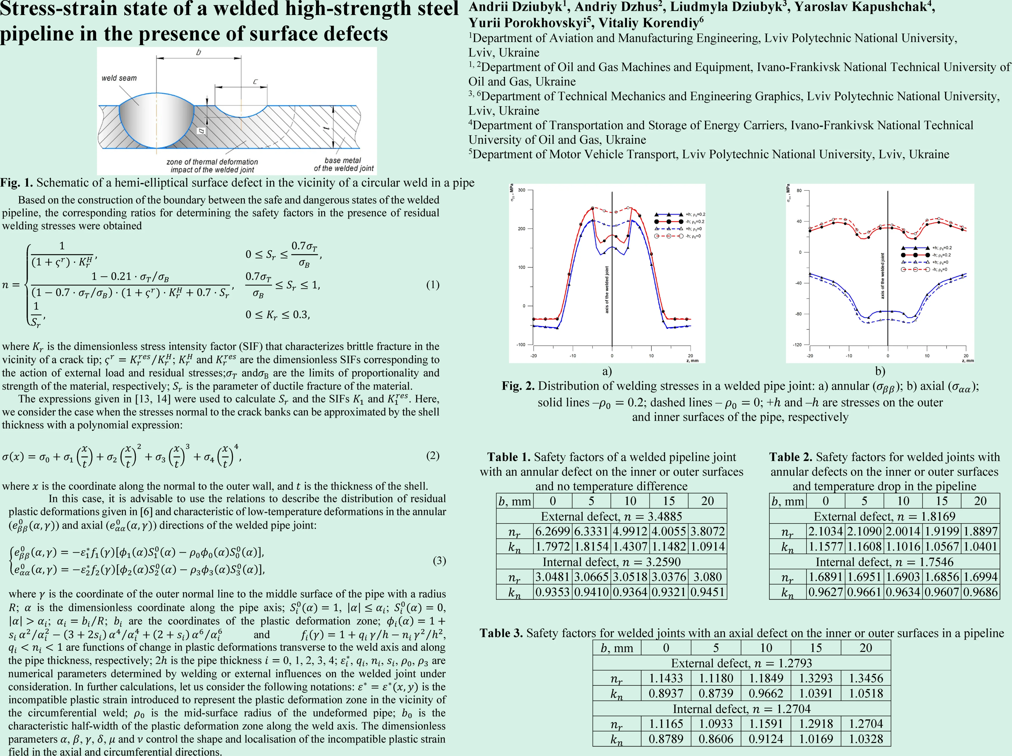
The static strength of a welded joint of high-strength steel pipes in the presence of a surface defect was studied using the two-parameter criterion of brittle-viscous material fracture. The analytical solution is presented in detail in [11, 16, 26, 27] and allows us to take into account the mechanical characteristics of the material and the available residual welding stresses. However, it should be noted that the approaches used in this work and the implemented software make it possible to study the strength of the pipeline at an arbitrary position of the defect relative to the weld axis. A schematic of a surface defect on the outside of a pipe modeled by a hemi-elliptical crack with semi-axes and , with a pipe thickness and a distance from the weld axis is shown in Fig. 1. Similar notations are used for the defect located on the inside of the pipe. This approach to modeling defects by a crack is more conservative, but is justified for the critical structure under consideration – the main pipeline.
Fig. 1Schematic of a hemi-elliptical surface defect in the vicinity of a circular weld in a pipe
Depending on the distance taken from the defect center to the weld axis (), the defect can be located both on the weld axis and in the zone of thermal deformation of the welded joint and thus be subject to different effects of residual welding stresses. It should be noted that as the defect moves away from the weld axis into the base metal by a considerable distance, the defect will be subjected only to the operational loads caused by internal pressure.
Based on the construction of the boundary between the safe and dangerous states of the welded pipeline, the corresponding ratios for determining the safety factors in the presence of residual welding stresses were obtained [11, 16, 26, 27]:
where is the dimensionless stress intensity factor (SIF) that characterizes brittle fracture in the vicinity of a crack tip; ; and are the dimensionless SIFs corresponding to the action of external load and residual stresses; and are the limits of proportionality and strength of the material, respectively; is the parameter of ductile fracture of the material.
Then, using the relevant regulatory documents [11, 16, 26, 27], it is possible to establish the level of danger of the defect and the possibility of continuing the operation of the pipeline. It is also possible to make managerial decisions on the scope of repair work, the characteristics of the work, and the repair methods used, the reduction of transportation operating pressures before the start of repairs, etc.
The expressions given in [13, 14] were used to calculate and the SIFs and . Here, we consider the case when the stresses normal to the crack banks can be approximated by the shell thickness with a polynomial expression:
where is the coordinate along the normal to the outer wall, and is the thickness of the shell.
At the same time, appropriate software has been developed to calculate the influence coefficients included in the expressions for calculating the SIFs and given in the special literature [11, 13, 14, 16] in the form of tables. It makes it possible to calculate these coefficients for a wide range of pipe geometric characteristics and crack sizes. This takes into account the relevant limitations given in [11, 16, 13, 14]: , , , where is the radius of the pipe’s center surface. Also, the average value of the acting residual stresses in the vicinity of a hemi-elliptical defect of certain geometric dimensions was determined.
To evaluate and take into account the effect of residual welding stresses on the static strength of the pipeline, we use a special influence factor , which is given in [6]. It determines the ratio between the calculated values of the safety factors of the pipeline in the zone of residual stresses () and outside this zone ().
To use Eqs. (1) and (2), it is necessary to have information on the stress distribution in an arbitrary cross-section of a welded pipe joint. Therefore, in this case, it is most appropriate to apply the experimental and computational method analyzed above. The essence and features of solving the inverse problems, based on the use of available data, are presented in [11, 12, 15, 16, 27, 28]. In this case, it is advisable to use the relations to describe the distribution of residual plastic deformations given in [6] and characteristic of low-temperature deformations in the annular () and axial () directions of the welded pipe joint:
where is the coordinate of the outer normal line to the middle surface of the pipe with a radius ; is the dimensionless coordinate along the pipe axis; , ; , ; ; are the coordinates of the plastic deformation zone; and , are functions of change in plastic deformations transverse to the weld axis and along the pipe thickness, respectively; 2 is the pipe thickness 0, 1, 2, 3, 4; , , , , , are numerical parameters determined by welding or external influences on the welded joint under consideration. In further calculations, let us consider the following notations: is the incompatible plastic strain introduced to represent the plastic deformation zone in the vicinity of the circumferential weld; is the mid-surface radius of the undeformed pipe; is the characteristic half-width of the plastic deformation zone along the weld axis. The dimensionless parameters , , , , and control the shape and localisation of the incompatible plastic strain field in the axial and circumferential directions.
Based on the method proposed in [11, 12, 15, 16, 27, 28] for solving the problem of residual stresses caused by an incompatible field of plastic deformations, a solution was obtained for the case of pipe welding, taking into account Eq. (3). This made it possible to formulate expressions for calculating axial and annular stresses in a welded pipe joint:
where ; 1, 2; 1, 2, 3; is the deflection of the shell; .
Eqs. (4) and (5) include arbitrary numerical parameters , , , , , , characterizing the distribution of residual deformations . These parameters depend not only on the welding method and modes. Their value is also affected by the welding process technique, spatial position, presence of external disturbing factors, etc. Therefore, for specific welded joints, these parameters are determined based on solving the inverse problem of the theory of shells [11, 12, 15, 16, 27, 28] using available experimental data.
In this work, the numerical parameters , , , , and describing the incompatible plastic deformation field in Eq. (3) were obtained using an experimental-computational identification procedure. Residual stress fields were first measured for full-scale welded joints of main-pipeline pipes by the optical speckle-interferometry method, as described in detail in [15, 16]. On the basis of these experimental data, the inverse problem of the shell theory with intrinsic strains was solved by minimizing a discrepancy functional between calculated and measured displacements and strains, following the methodology outlined in [11, 12, 27, 28]. For the present analysis, we use the set of parameters calibrated and validated in [6, 27] for high-strength steel pipes of similar diameter, wall thickness and welding procedure, which ensures that the reconstructed axial and annular residual stresses reproduce the measured profiles with sufficient accuracy.
4. Research results
The static strength of the welded joint was calculated for the case of a high-strength steel pipeline with a diameter of 1020 mm and a wall thickness of 12 mm. The mechanical characteristics of the steel, the value of the internal pressure, and the numerical parameters of the plastic deformation field were taken similarly to the data given in [6, 27]: 2.1×10⁵ MPa; ; MPa; MPa; MPa; ; ; ; ; ; ; 0.6. The values of were taken equal to 0.25.
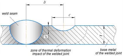
When calculating residual stresses, the influence of the numerical parameters , , on the nature of stress changes was studied. In particular, Fig. 2 shows the distribution of annular stresses, which are larger in magnitude compared to axial stresses and are predominantly tensile. The calculations were performed for zero values of the studied numerical parameters (; ; 0), similar to those established in [6] (dashed lines), and also for the following accepted values of numerical parameters: 5, 3 (solid lines). For convenience, the calculation results are denoted as 0 and 0.2, respectively.
The analysis of the results shows that the use of numerical parameters , , makes it possible to obtain a local minimum stress on the weld axis with a shift of the maximum values to the zone of thermo-deformation influence. Such a characteristic stress state is typical for welds with low-temperature structural transformations such as austenite or bainite [6, 19, 20]. With the distance from the weld axis, the distribution curves of the annular stresses (Fig. 2(a)) coincide, and the axial stresses (Fig. 2(b)) are similar in nature. That is, the proposed relations Eqs. (3)-(5) provide an extension of the scope of the mathematical model of the considered experimental and computational method.
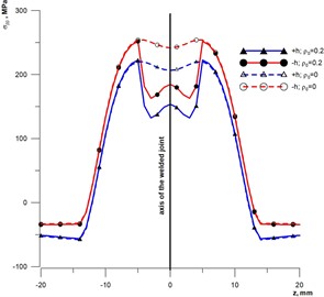
Fig. 2Distribution of welding stresses in a welded pipe joint: a) annular (σββ); b) axial (σαα); solid lines –ρ0= 0.2; dashed lines – ρ0= 0; +h and –h are stresses on the outer and inner surfaces of the pipe, respectively
a)
b)
The parameters of the surface defect under consideration (Fig. 1) were taken as follows: 3 mm; 3 mm; . The location of the defect was considered for the following cases: outside and inside the pipe. The distance from the weld axis (, mm) varied from 0 mm to 20 mm in 5 mm increments. The calculation of the safety factors in the zone of residual stresses () and outside this zone () and the influence factor () was performed for the stress distribution shown in Fig. 2 at the accepted values of the numerical parameters: ; ; . In this case, it is assumed that the temperature difference (), which causes the occurrence of axial force in the pipeline, is absent.
The results of calculations for an annular defect in a welded joint on the inner or outer surfaces at different distances from the weld axis are given in Table 1.
The results show that in the absence of residual stresses, the safety factors remain constant at different distances from the weld axis. However, the presence of axial residual stresses from the welding cycle introduces changes in the value of the safety factor. This influence is not unambiguous, in particular, in the case of compressive stresses on the outer surface of the pipeline (Fig. 2(b)), the safety factor () will increase significantly compared to the values of the factor outside the weld (). At the same time, tensile stresses on the inner surface of the pipeline (Fig. 2(b)), on the contrary, reduce the value of this coefficient () compared to the value of the coefficient () outside the weld. With the distance from the weld axis, the stress value decreases, which brings the values of the considered strength factors () and () closer to each other. This tendency can be clearly observed in the values of the residual stress influence factor. The results obtained correlate well with those reported in the specialized literature [6].
If the temperature difference () in the pipe body is taken into account, which is typical for open sections of pipelines, in particular beam crossings over obstacles [17, 18], an additional axial tensile force arises. Therefore, this axial force will reduce the value of the pipeline safety factor. The calculation results for the case of a temperature difference of +30 °C are shown in Table 2.
Therefore, when examining above-ground pipeline sections, it is important to establish the temperature of the structure (the so-called welded joint closure temperature) and compare it with the observed temperature conditions. In this case, it should be noted that the effect of compressive stresses from welding is less on the investigated value of the safety factor (). However, in terms of absolute value, these safety factors () still exceed similar values outside the weld ().
Table 1Safety factors of a welded pipeline joint with an annular defect on the inner or outer surfaces and no temperature difference
, mm | 0 | 5 | 10 | 15 | 20 |
External defect, 3.4885 | |||||
6.2699 | 6.3331 | 4.9912 | 4.0055 | 3.8072 | |
1.7972 | 1.8154 | 1.4307 | 1.1482 | 1.0914 | |
Internal defect, 3.2590 | |||||
3.0481 | 3.0665 | 3.0518 | 3.0376 | 3.080 | |
0.9353 | 0.9410 | 0.9364 | 0.9321 | 0.9451 | |
Table 2Safety factors for welded joints with annular defects on the inner or outer surfaces and temperature drop in the pipeline
, mm | 0 | 5 | 10 | 15 | 20 |
External defect, 1.8169 | |||||
2.1034 | 2.1090 | 2.0014 | 1.9199 | 1.8897 | |
1.1577 | 1.1608 | 1.1016 | 1.0567 | 1.0401 | |
Internal defect, 1.7546 | |||||
1.6891 | 1.6951 | 1.6903 | 1.6856 | 1.6994 | |
0.9627 | 0.9661 | 0.9634 | 0.9607 | 0.9686 | |
In both cases under consideration (Table 1 and Table 2), the absolute values of axial stresses () and their change with distance from the weld axis (Fig. 2(b)) were not significant, and therefore the effect on the value of the safety factor of these stresses was proportional. However, the study of annular stresses () shows that their magnitude can reach significant absolute values. The gradient of these stresses is also characterized by a significant difference (Fig. 2(a)). To study the effect of annular stresses, we consider the static strength of a pipeline with axial defects. The temperature difference for this type of defect does not affect the static strength of the pipeline, since it causes axial, not annular, stress. Table 3 shows the values of the safety factors and the impact of the pipeline section with surface axial defects in the vicinity of the welded joint.
Table 3Safety factors for welded joints with an axial defect on the inner or outer surfaces in a pipeline
, mm | 0 | 5 | 10 | 15 | 20 |
External defect, 1.2793 | |||||
1.1433 | 1.1180 | 1.1849 | 1.3293 | 1.3456 | |
0.8937 | 0.8739 | 0.9662 | 1.0391 | 1.0518 | |
Internal defect, 1.2704 | |||||
1.1165 | 1.0933 | 1.1591 | 1.2918 | 1.2704 | |
0.8789 | 0.8606 | 0.9124 | 1.0169 | 1.0328 | |
Analysis of the data in Table 3 shows that an increase in the absolute values of tensile ring stresses significantly reduces the safety factor (). At the same time, the minimum values of () are observed outside the central section of the weld in the area of the zone of thermal deformation. Further, there is a gradual increase in the coefficient (), which is probably due to a rapid decrease in tensile stresses with the transition to compressive stresses (Fig. 2(a)). For the inner side of the pipe, the safety factor () is lower compared to the outer side. However, the pattern of change in the absolute values of the coefficients () is similar for both sides.
From the viewpoint of the adopted two-parameter fracture criterion, the safety factor nr defines the ratio between the critical load (or stress intensity) and the applied load for a given defect size. Thus, 1.0 corresponds to the boundary of admissibility, whereas 1.0 indicates that the assessment point lies inside the safe region of the failure assessment diagram, and 1.0 indicates that the defect is not acceptable at the considered load level. This interpretation is consistent with fitness-for-service methodologies such as API 579-1/ASME FFS-1, where acceptability is formulated in terms of remaining strength or safety factors and failure assessment diagrams for crack-like flaws [13]. In practice, values of nr slightly below 1.0 (for example, the minimum 0.8937 in Table 3) indicate that, at the assumed internal pressure, an axial defect located in the HAZ does not satisfy the fitness-for-service acceptance criteria and would require mitigation measures. Such measures typically include a reduction of the allowable operating pressure (re-rating) to obtain , followed by repair or replacement during the next maintenance interval. For long-term safe operation, industrial practice often requires additional margins (for example 1.1…1.2) depending on the reliability class of the pipeline and the consequences of failure.
5. Conclusions
The use of high-strength steels for the manufacture of main pipelines requires the use of methods for diagnosing residual welding stresses that take into account the presence of low-temperature transformations in the zone of thermal deformation. In this case, the nature of the stresses is characterized by the presence of several local extremes with a shift of the largest values to the areas of the base metal of the welded joint adjacent to the weld.
Establishing the static strength of welded joints of high-strength steels in the presence of surface defects requires determining not only the operating loads, but also the residual stresses and geometric position of the defect. This is due to the ambiguous effect of welding stresses on the value of the safety factor. In particular, in the presence of compressive stresses, the safety factor will increase, and in the presence of tensile stresses, it will decrease. In the case of high-strength steels, the lowest values of safety factors are found in the zone of thermal deformation in the presence of tensile residual stresses. Given the same geometric dimensions of defects, defects located on the inner surface of the pipe are more dangerous, since the safety factors are smaller.
The obtained minimum values of the safety factor nr for axial defects in the HAZ (down to 0.89) indicate that such defect configurations are not acceptable at the considered internal pressure and require either pressure reduction or repair according to a fitness-for-service assessment consistent with API 579-1/ASME FFS-1.
In summary, the introduction of the parameters , and into the residual-stress model enables a realistic description of stress maxima shifted into the HAZ of high-strength steels, and the analysis of defects at different locations relative to the weld axis quantifies their influence on safety factors within a fitness-for-service framework.
References
-
D. Belato Rosado, W. de Waele, D. Vanderschueren, and S. Hertelé, “Latest developments in mechanical properties and metallurgical features of high strength line pipe steels,” International Journal Sustainable Construction and Design, Vol. 4, No. 1, Mar. 2013, https://doi.org/10.21825/scad.v4i1.742
-
Z. Chuanguo, Z. Lei, H. Ping, Z. Bei, W. Kougen, and H. Weifeng, “Research and development of ultra-high strength X100 welded pipe,” in Energy Materials 2014, pp. 613–621, Jan. 2014, https://doi.org/10.1007/978-3-319-48765-6_74
-
D. Yu. Petryna and L. G. Petryna, “Influence of a corrosive environment on modern steel main pipelines,” Prospecting and Development of Oil and Gas Fields, Vol. 2, No. 83, pp. 95–104, Jun. 2022, https://doi.org/10.31471/1993-9973-2022-2(83)-95-104
-
V. Vira et al., “Peculiarities of fatigue crack growth in steel 17H1S after long-term operations on a gas pipeline,” Materials, Vol. 16, No. 8, p. 2964, Apr. 2023, https://doi.org/10.3390/ma16082964
-
L. I. Nyrkova, S. O. Osadchuk, L. V. Goncharenko, A. O. Rybakov, and Y. O. Kharchenko, “Influence of long-term operation on the properties of main gas pipeline steels. A review,” Physics and Chemistry of Solid State, Vol. 25, No. 1, pp. 191–202, Feb. 2024, https://doi.org/10.15330/pcss.25.1.191-202
-
A. Dzyubyk, L. Dzyubyk, and O. Soloviov, “Effect of welding axial stresses on the strength of a welded pipe joint with a defect,” Vibroengineering Procedia, Vol. 55, No. 55, pp. 187–193, Sep. 2024, https://doi.org/10.21595/vp.2024.24371
-
N. Murao, N. Hisamune, H. Osako, and K. Kondo, “High strength seamless steel pipe excellent in hydrogen-induced cracking resistance and its production method,” European Patent EP 1 546 417 B1, 2012.
-
R. D. Vieira, G. N. N. Idarilho, and F. Arroyo, “Line pipe manufacturing processes,” in Handbook of Pipeline Engineering, Cham: Springer International Publishing, 2024, pp. 311–365, https://doi.org/10.1007/978-3-031-33328-6_10
-
A. Służalec, Theory of Thermomechanical Processes in Welding. Dordrecht: Springer Netherlands, 2005, https://doi.org/10.1007/1-4020-2991-8
-
A. Dzyubyk, L. Lisovska, A. Voitovich, I. Khomych, O. Soloviov, and L. Dzyubyk, “Investigation in structure of fusion zone of welded joint of high-strength steel with austenite weld,” in Lecture Notes in Networks and Systems, Cham: Springer Nature Switzerland, 2024, pp. 346–355, https://doi.org/10.1007/978-3-031-66268-3_34
-
V. A. Osadchuk, Y. V. Banakhevych, and O. O. Ivanchuk, “Determination of the stressed state of main pipelines in the zones of circular welds,” Materials Science, Vol. 42, No. 2, pp. 256–262, Mar. 2006, https://doi.org/10.1007/s11003-006-0078-5
-
V. A. Osadchuk and T. M. Nykolyshyn, “Limiting equilibrium of a welded joint of gas main,” Materials Science, Vol. 36, No. 2, pp. 285–291, Mar. 2000, https://doi.org/10.1007/bf02767550
-
“Recommended practice for fitness-for-service,” American Petroleum Institute, Washington, DC, USA, 1990.
-
A. Zahoor, Ductile Fracture Handbook. Novotech: Cop & EPRI, 1990.
-
V. A. Osadchuk and Y. V. Banakhevych, “Estimation of the admissibility of circular-crack-type defects in the zone of welded field joints of main pipelines,” Journal of Mathematical Sciences, Vol. 178, No. 4, pp. 409–420, Oct. 2011, https://doi.org/10.1007/s10958-011-0558-5
-
Y. V. Banakhevych, A. V. Dragilev, and A. O. Kychma, “Diagnostics of the stress-strain state of multilayer annular welded joints of pipelines,” Materials Science, Vol. 50, No. 2, pp. 217–223, Dec. 2014, https://doi.org/10.1007/s11003-014-9711-x
-
A. R. Dzyubyk, L. V. Dzyubyk, G. V. Pokhmurs’ka, and I. A. Prokopyshyn, “Residual strength of the overhead section of a main pipeline with annular cracks,” Materials Science, Vol. 54, No. 6, pp. 855–865, Nov. 2019, https://doi.org/10.1007/s11003-019-00273-4
-
M. Dutkiewicz, A. Andrusyak, A. Kychma, V. Vytvytskyi, and A. Velychkovych, “Numerical model of interaction of a mobile lift chain with a main gas pipeline pipe in the process of repair work,” Eksploatacja i Niezawodność – Maintenance and Reliability, Vol. 26, No. 3, Apr. 2024, https://doi.org/10.17531/ein/187159
-
A. R. Dzyubyk, A. A. Voitovych, L. V. Dzyubyk, and L. O. Babii, “Specific features of the fatigue fracture of welded joints of 34KhN2MA steel formed by electrodes with different phase compositions,” Materials Science, Vol. 54, No. 2, pp. 215–222, Nov. 2018, https://doi.org/10.1007/s11003-018-0176-1
-
A. R. Dzyubyk, “Impact toughness of welded joints on 34KhN2MA steel produced from electrodes with various phase compositions,” Materials Science, Vol. 56, No. 2, pp. 203–209, Nov. 2020, https://doi.org/10.1007/s11003-020-00416-y
-
O. I. Balyts’Kyi, “The International Conference “Welded Structures”,” in Materials Science, Vol. 36, No. 6, pp. 941–942, Nov. 2000, https://doi.org/10.1023/a:1011367628423
-
O. M. Berdnikova, “Physico-mechanical properties of welded joints of high-strength steel with the yield strength of 690-1300 MPa,” The Paton Welding Journal, Vol. 2021, No. 4, pp. 2–8, Apr. 2021, https://doi.org/10.37434/tpwj2021.04.01
-
O. V. Makhnenko, A. S. Milenin, E. A. Velikoivanenko, N. I. Pivtorak, and D. V. Kovalchuk, “Modelling of temperature fields and stress-strain state of small 3D sample in its layer-by-layer forming,” The Paton Welding Journal, Vol. 2017, No. 3, pp. 7–14, Mar. 2017, https://doi.org/10.15407/tpwj2017.03.02
-
O. V. Makhnenko, A. S. Milenin, and G. Y. Saprykina, “Evaluation of operability of WWR-M reactor primary circuit piping with welded joint defects,” The Paton Welding Journal, Vol. 2015, No. 1, pp. 49–54, Jan. 2015, https://doi.org/10.15407/tpwj2015.01.08
-
W. Kong, W. Huang, and Y. Wei, “Numerical study on welding residual stress by double-sided submerged arc welding for orthotropic steel deck,” Engineering Structures, Vol. 302, p. 117445, Mar. 2024, https://doi.org/10.1016/j.engstruct.2024.117445
-
A. Kychma and R. Predko, “Estimation of residual stresses for multi-layer circumferential welds of oil and gas pipelines,” Diagnostyka, Vol. 20, No. 4, pp. 11–18, Sep. 2019, https://doi.org/10.29354/diag/112396
-
V. A. Osadchuk, L. I. Tsymbalyuk, and A. R. Dzyubyk, “Determination of the triaxial distribution of residual stresses in welded joints of structural elements with rectilinear seams and estimation of their influence on joint strength in the presence of crack-type defects,” Journal of Mathematical Sciences, Vol. 183, No. 2, pp. 150–161, Apr. 2012, https://doi.org/10.1007/s10958-012-0803-6
-
A. Dzyubyk, Y. Kusyi, L. Dzyubyk, I. Nazar, and V. Ivanov, “Influence of the welding cycle on the parameters of material damageability of the high-strength steel connection with an austenitic seam,” Vibroengineering Procedia, Vol. 55, No. 55, pp. 201–207, Sep. 2024, https://doi.org/10.21595/vp.2024.24483
About this article

The authors have not disclosed any funding.
The datasets generated during and/or analyzed during the current study are available from the corresponding author on reasonable request.
The authors declare that they have no conflict of interest.
