Abstract
The object of the study is multiple-unit rolling stock with a pneumatic suspension system. To evaluate the dynamic safety indicators of train operation, namely ride smoothness, full-scale experimental dynamic tests of the multiple-unit rolling stock were conducted under actual operating conditions. The tests involved attaching analog acceleration sensors to the upper mounting plate of the pneumatic spring. Using modern ADXL-335 analog accelerometers combined with an ESP-32 microcontroller, acceleration records of the car body in vertical and horizontal directions were obtained. It was established that the root mean square acceleration in the vertical direction is 0.278-0.312 m/s2, in the horizontal direction – 0.206-0.251 m/s2, while the ride smoothness index W lies within the following ranges: for the vertical direction – 2.96-3.06; for the horizontal – 2.91-3.09. The obtained results can further be used to verify the adequacy of the outcomes derived from theoretical mathematical models.
Highlights
- Developed a full-scale experimental methodology using ADXL-335 sensors and ESP-32 microcontrollers to evaluate railway ride smoothness under actual operating conditions.
- Vertical root mean square accelerations reached 0.278-0.312 m/s^2, with a ride smoothness index W of 2.96-3.06, ensuring passenger comfort in modern rolling stock.
- Horizontal accelerations measured 0.206-0.251 m/s^2, resulting in a W index of 2.91-3.09, which falls within the regulatory limit of 3.25 for passenger transport.
- Experimental results validate the effectiveness of pneumatic suspension systems and provide a reliable basis for verifying the adequacy of theoretical mathematical models.
1. Introduction
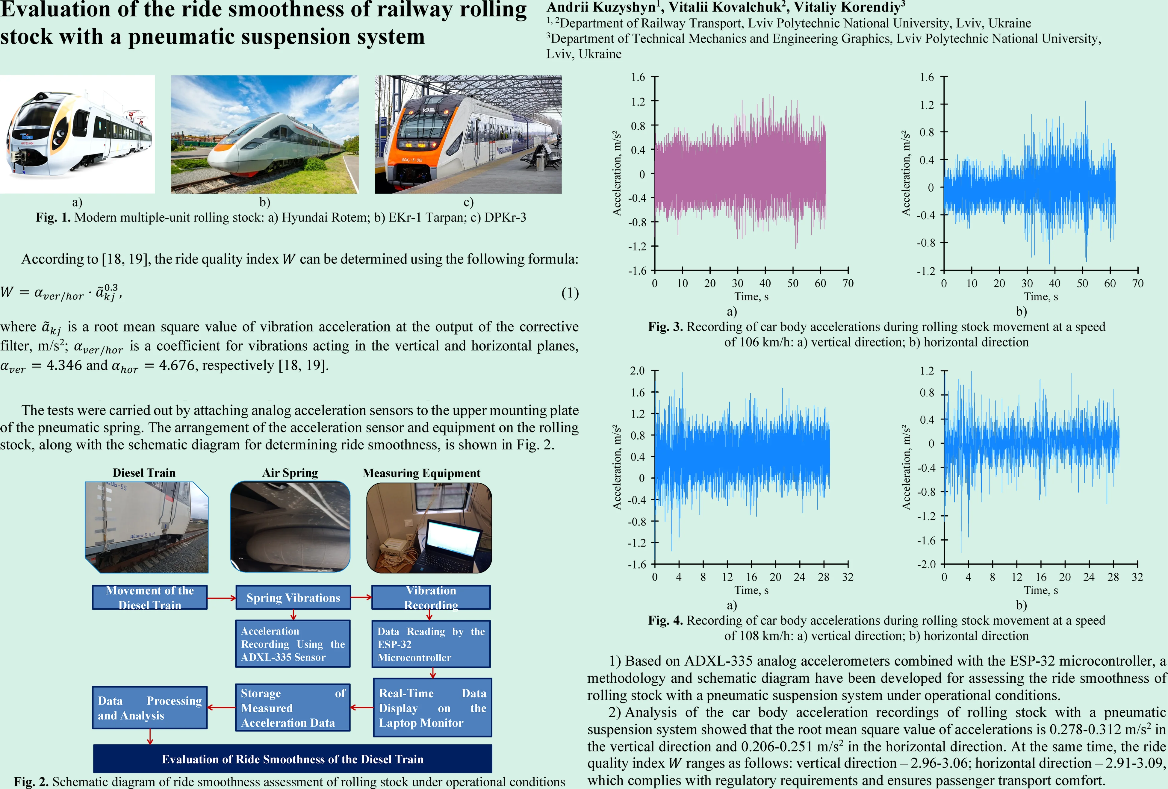
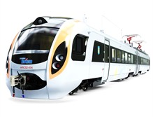
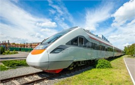
One of the ways to develop railway transport is to increase the line’s throughput and carrying capacity. Ensuring such an increase primarily involves raising the operating speeds of rolling stock, which is possible through the use of modern railway vehicles. Modern rolling stock that provides passenger transportation in interregional service includes Hyundai Rotem and EKr-1 Tarpan electric trains, as well as DPKr-2 and DPKr-3 diesel trains (Fig. 1).
Fig. 1Modern multiple-unit rolling stock: a) Hyundai Rotem; b) EKr-1 Tarpan; c) DPKr-3
а)
b)
c)
A key common structural component of these trains is the use of a pneumatic suspension system in the secondary suspension stage. This system includes a pneumatic spring, an additional reservoir, a connecting pipeline, height control valves, and other components. Such a system primarily improves the elastic and damping properties in the connections between the structural elements of the rolling stock and determines the overall level of forces and accelerations that arise during motion [1-3]. Car body accelerations serve as the main factor in evaluating ride smoothness, which is assessed separately for vertical and horizontal (lateral) vibration directions. Therefore, the study of the ride smoothness index of rolling stock with a pneumatic suspension system is a relevant task, as it allows for the assessment of passenger comfort and the quality of transport services.
2. Literature review and problem statement
Evaluation of the ride smoothness of rolling stock during its interaction with the railway track can be carried out both theoretically and experimentally. Significant progress in the implementation of theoretical methods for studying ride smoothness has been achieved through computer modeling, which involves two steps. The first step is the development of a mathematical model using a selected type of mathematical description: algebraic, differential, or integral equations; the second step is the choice of a method for solving these models. However, verification of the adequacy of the obtained theoretical results is only possible through experimental studies.
Experimental methods of investigating the object are conducted under conditions corresponding to its actual operational use, thereby ensuring the acquisition of the most reliable results that take real service conditions into account.
Considering this, we will analyze scientific works in which the main task was to evaluate the ride smoothness of rolling stock with a pneumatic suspension system.
In [4], the influence of the pneumatic suspension system on the ride comfort of rolling stock is investigated. The study was carried out on a test bench, and the obtained results were compared with theoretical models for correlation. It was proposed to improve comfort by applying a valve with a variable orifice diameter in the connecting pipeline between the pneumatic spring and the additional reservoir. Ride comfort was assessed by evaluating accelerations at two locations on the car body, which mainly highlighted the difficulty of selecting the optimal damping coefficient for the pneumatic suspension system.
In [5], the authors describe the modeling of several types of pneumatic spring models, namely a simple spring-damper model, as well as the Nishimura [6], Vampire [7], Simpack [8], and Gensys [9] models. Later, the pneumatic spring model was implemented in a multi-mass model of a railway vehicle, and the dynamic behavior of the car body, bogie, and wheelset of the rolling stock was studied during its interaction with a railway track featuring a sinusoidal irregularity with an amplitude of 0.1 m.
In [10-11], the authors proposed a thermodynamic model to study the operation of the pneumatic suspension system. To verify the adequacy of the theoretical results, full-scale tests were carried out on an IRICo DMU train consisting of four cars: two motor cars and two trailers. It was found that at a speed of 80 km/h, the power spectral density of vertical car body accelerations shows maximum values in the frequency range of 1.5 Hz to 3 Hz. However, it was shown that the pneumatic suspension system is most effective in damping vertical vibrations at frequencies of around 6 Hz. Thus, by using a new set of suspension parameters, passenger comfort improves, and the ride comfort index decreases by approximately 10 %.
In [12], the authors developed two different approaches to modeling the operation of the pneumatic suspension system: quasi-static and dynamic. The results of dynamic tests carried out on the pneumatic suspension showed that the suspension behavior depends on the frequency in the range of 0-20 Hz, which may be of significant importance for assessing ride quality. It was found that with the “short pipe” configuration, a considerable amplification of car body accelerations is observed in the frequency range of 5-10 Hz. In the case of the “long pipe” configuration, pneumatic resonance occurs at a lower frequency compared to the “short pipe” configuration, and from 3 Hz an amplification of the dynamic response can be observed, causing significant dynamic amplification effects at 3 Hz and 5 Hz. It was demonstrated that a dynamic model of the pneumatic spring is necessary for proper assessment of ride comfort, especially when the pneumatic suspension scheme includes a long pipe between the pneumatic spring and the reservoir.
In [13], the operation of the pneumatic system was analyzed considering the nonlinear action of leveling valves and the pressure difference between pneumatic springs. Particular attention was given to the influence of the flow characteristics through the leveling valve on the occurrence of wheel load imbalance when the rolling stock passes curved track sections. The importance of this modeling approach was established for evaluating the level of running safety at low speeds, especially on curved track sections. In [14], the authors examined how changing the angle of the leveling valve lever affects the distribution of loads between wheels when running on curved sections with a small radius.
In [15], the authors carried out mathematical modeling of the pneumatic spring both in the vertical and horizontal directions. In the vertical direction, the reaction force of the pneumatic spring was obtained through the derivation of pneumatic equations, while in the horizontal direction it was determined using the finite element method. It was found that when simulating the movement of rolling stock along a straight section of track, vertical ride comfort improves significantly, as the stiffness and damping of the spring can adapt to external disturbances. When simulating motion in curves, the transverse and longitudinal stiffness of the pneumatic spring increased due to the lateral displacement of the car body relative to the bogie, which in turn reduced the vehicle’s ability to negotiate curves.
In [16], the authors investigated the lateral characteristics of the pneumatic spring system. The lateral model consists of three parallel elements: the stiffness of the rubber diaphragm, the stiffness of the emergency spring, and the damping coefficient. Considering that the magnitude of car body acceleration is closely related to vibrations, the standard ENV 12299 [17] was used to evaluate the ride comfort index. It was established that increasing the vertical sprung load can reduce lateral acceleration and improve the ride comfort of rolling stock.
Analyzing the research studies [4-17], it can be concluded that there is a considerable amount of work devoted to passenger comfort in high-speed rolling stock equipped with pneumatic suspension systems. It was also determined that a significant portion of the studies are based on theoretical methods, whereas the verification of their adequacy requires full-scale testing. Therefore, conducting full-scale studies of the dynamic behavior of rolling stock with pneumatic suspension systems during interaction with the track is a relevant task, as it allows for the evaluation of its dynamic performance and determination of the level of passenger comfort.
3. Purpose and objectives of the study
The aim of this study is to experimentally determine the ride smoothness index of modern multiple-unit rolling stock with a pneumatic suspension system. To achieve this aim, the following tasks must be carried out: develop a full-scale method for evaluating the ride smoothness of rolling stock with a pneumatic suspension system; obtain records of vertical and horizontal car body accelerations during the movement of rolling stock on continuous welded rail sections and, based on their root mean square values, determine the ride smoothness indices.
4. Methodology for field determination of ride smoothness of rolling stock with a pneumatic suspension system
During the operation of passenger rolling stock, particular attention is paid to ensuring a high level of passenger comfort. Compliance with established requirements is assessed through running and acceptance tests. Ride smoothness is evaluated in conventional units of the ride quality index , which characterizes the running qualities of a railcar and is determined by the intensity and spectral composition of its vibrations. The evaluation of the railcar’s ride smoothness is carried out separately for the vertical and horizontal (lateral) directions of vibrations. During testing, the technical condition of the track must meet the “good” criteria according to the current control methods applied in railway transport and must allow the tested rolling stock to operate at the design speed.
According to [18, 19], the ride quality index can be determined using the following formula:
where is a root mean square value of vibration acceleration at the output of the corrective filter, m/s2; is a coefficient for vibrations acting in the vertical and horizontal planes, and , respectively [18, 19].
The limiting value of the ride quality coefficient is accepted as 3.25 [18, 19].
Therefore, to study ride smoothness, field experimental dynamic tests were conducted on motorized rolling stock with a pneumatic suspension system under its operational conditions.
The tests were carried out by attaching analog acceleration sensors to the upper mounting plate of the pneumatic spring. The arrangement of the acceleration sensor and equipment on the rolling stock, along with the schematic diagram for determining ride smoothness, is shown in Fig. 2.
Fig. 2Schematic diagram of ride smoothness assessment of rolling stock under operational conditions
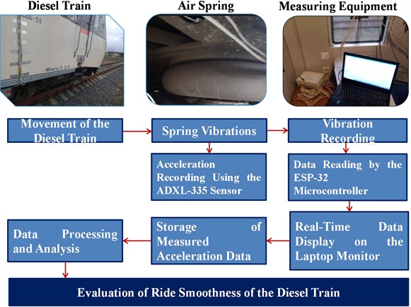
The tests were carried out using modern analog accelerometers ADXL-335 in combination with an ESP-32 microcontroller. The signals from the accelerometer are read by the microcontroller and transmitted to a laptop via a USB 3.0 interface. The acquired data are stored in the computer’s memory and subsequently processed and analyzed in laboratory conditions.
The spring testing methodology involved measuring accelerations as the rolling stock passed along straight sections of the track. For the analysis, only sections of continuous welded rail (CWR) in technically sound condition were considered. This allows for a more accurate determination of the car body’s dynamic parameters, as additional disturbance factors from the track do not affect the vibrations.
5. Results obtained
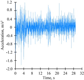
The results of acceleration recordings during the movement of rolling stock along sections of continuous welded rail at speeds of 106-108 km/h are shown in Figs. 3, 4.
Based on the results of the dynamic tests, the ride quality index of the motorized rolling stock is evaluated in the vertical and horizontal directions.
As a result of signal processing in the Matlab software environment, it was determined that the root mean square value of accelerations in the vertical direction ranges from 0.278 to 0.312 m/s2, and in the horizontal direction from 0.206 to 0.251 m/s2.
Using Eq. (1), it was established that the ride quality index falls within the following ranges: for the vertical direction – 2.96-3.06; for the horizontal direction – 2.91-3.09.
Thus, the obtained values of the ride quality index allow us to conclude that the comfort of passenger transportation is ensured for modern motorized rolling stock. Moreover, the use of this method makes it possible to verify the adequacy of results obtained using theoretical mathematical models.
Fig. 3Recording of car body accelerations during rolling stock movement at a speed of 106 km/h: a) vertical direction; b) horizontal direction
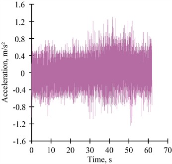
а)
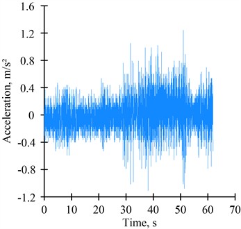
b)
Fig. 4Recording of car body accelerations during rolling stock movement at a speed of 108 km/h: a) vertical direction; b) horizontal direction
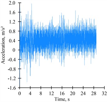
а)
b)
6. Conclusions
1) Based on ADXL-335 analog accelerometers combined with the ESP-32 microcontroller, a methodology and schematic diagram have been developed for assessing the ride smoothness of rolling stock with a pneumatic suspension system under operational conditions.
2) Analysis of the car body acceleration recordings of rolling stock with a pneumatic suspension system showed that the root mean square value of accelerations is 0.278-0.312 m/s2 in the vertical direction and 0.206-0.251 m/s2 in the horizontal direction. At the same time, the ride quality index ranges as follows: vertical direction – 2.96-3.06; horizontal direction – 2.91-3.09, which complies with regulatory requirements and ensures passenger transport comfort.
References
-
A. Kuzyshyn, V. Kovalchuk, V. Stankevych, and V. Hilevych, “Determining patterns in the influence of the geometrical parameters of the connecting pipeline on the dynamic parameters of the pneumatic spring of railroad rolling stock,” Eastern-European Journal of Enterprise Technologies, Vol. 1, No. 7 (121), pp. 57–65, Feb. 2023, https://doi.org/10.15587/1729-4061.2023.274180
-
A. Kuzyshyn, I. Khotsyanovych, I. Royko, V. Kirpita, and O. Turovets, “Determining the effect of additional tank volume and air pressure in the spring on the dynamic indicators of a pneumatic system of spring suspension in high-speed railroad rolling stock,” Eastern-European Journal of Enterprise Technologies, Vol. 3, No. 7(129), pp. 47–62, 2024.
-
A. Kuzyshyn, J. Sobolevska, S. Kostritsa, A. Batig, and V. Boiarko, “Mathematical modeling of the second stage of spring suspension of high-speed rolling stock,” in AIP Conference Proceedings, Vol. 2684, No. 1, p. 02000, 2023, https://doi.org/10.1063/5.0127705
-
A. Alonso, J. G. Giménez, J. Nieto, and J. Vinolas, “Air suspension characterisation and effectiveness of a variable area orifice,” Vehicle System Dynamics, Vol. 48, No. sup1, pp. 271–286, Dec. 2010, https://doi.org/10.1080/00423111003731258
-
M. Bayraktar, A. Zengin, M. Kellegöz, and A. Saltan, “Modelling of air springs in a rail vehicle,” in Proceedings of the 13th International Research/Expert Conference “Trends in the Development of Machinery and Associated Technology (TMT 2009)”, pp. 829–832, Oct. 2009.
-
N. Oda and S. Nishimura, “Vibration of air suspension bogies and their design,” Bulletin of JSME, Vol. 13, No. 55, pp. 43–50, Jan. 1970, https://doi.org/10.1299/jsme1958.13.43
-
M. Aizpun, J. Vinolas, and A. Alonso, “Using the stationary tests of the acceptance process of a rail vehicle to identify the vehicle model parameters,” Proceedings of the Institution of Mechanical Engineers, Part F: Journal of Rail and Rapid Transit, Vol. 228, No. 4, pp. 408–421, Feb. 2013, https://doi.org/10.1177/0954409713478592
-
C. Pellegrini, F. Gherardi, D. Spinelli, G. Saporito, and M. Romani, “Wheel-rail dynamic of DMU IC4 car for DSB: modeling of the secondary air springs and effects on calculation results,” Vehicle System Dynamics, Vol. 44, No. sup1, pp. 433–442, Jan. 2006, https://doi.org/10.1080/00423110600872960
-
M. Berg, “A three-dimensional airspring model with friction and orifice damping,” Vehicle System Dynamics, Vol. 33, pp. 528–539, 1999, https://doi.org/10.1080/00423119908969578
-
H. Sayyaadi and N. Shokouhi, “Improvement of passengers ride comfort in rail vehicles equipped with air springs,” Zenodo, Vol. 3, No. 5, pp. 592–598, May 2009, https://doi.org/10.5281/zenodo.1071388
-
H. Sayyaadi and N. Shokouhi, “New dynamics model for rail vehicles and optimizing air suspension parameters using GA,” Scientia Iranica, Transaction B: Mechanical Engineering, Vol. 16, No. 6, pp. 496–512, 2009.
-
A. Facchinetti, L. Mazzola, S. Alfi, S. Bruni, and P. Maggi, “Mathematical modelling of the secondary airspring suspension in railway vehicles and its effect on safety and ride comfort,” Vehicle System Dynamics, Vol. 48, pp. 429–449, 2010.
-
T. Nakajima, Y. Shimokawa, M. Mizuno, and H. Sugiyama, “Air suspension system model coupled with leveling and differential pressure valves for railroad vehicle dynamics simulation,” Journal of Computational and Nonlinear Dynamics, Vol. 9, No. 3, Jul. 2014, https://doi.org/10.1115/1.4026275
-
T. Tanaka and H. Sugiyama, “Prediction of railway wheel load unbalance induced by air suspension leveling valves using quasi-steady curve negotiation analysis procedure,” Proceedings of the Institution of Mechanical Engineers, Part K: Journal of Multi-body Dynamics, Vol. 234, No. 1, pp. 19–37, Aug. 2019, https://doi.org/10.1177/1464419319867179
-
Z. Qi, F. Li, and D. Yu, “A three-dimensional coupled dynamics model of the air spring of a high-speed electric multiple unit train,” Proceedings of the Institution of Mechanical Engineers, Part F: Journal of Rail and Rapid Transit, Vol. 231, No. 1, pp. 3–18, Aug. 2016, https://doi.org/10.1177/0954409715620534
-
L. Xu, “Research on nonlinear modeling and dynamic characteristics of lateral stiffness of vehicle air spring system,” Advances in Mechanical Engineering, Vol. 12, No. 6, pp. 1–15, Jun. 2014, https://doi.org/10.1177/1687814020930457
-
“Railway applications. Ride comfort for passengers. Measurement and evaluation,” EN 12299:2024, 2022.
-
“Passenger Coaches. Ride Comfort. Methods of Determination,” (in Ukrainian), Ministry of Industrial Policy of Ukraine, Kyiv, Ukraine, SOU MPP 45.060-204:2007, 2007.
-
“Mainline Passenger Coaches. Guidelines for Evaluating Passenger Comfort in Relation to Vibration (UIC 513:1994, IDT),” (in Ukrainian), Kyiv, Ukraine, DSTU UIC 513:2004, 2004.
About this article

The authors have not disclosed any funding.
The datasets generated during and/or analyzed during the current study are available from the corresponding author on reasonable request.
The authors declare that they have no conflict of interest.
