Abstract
Shaft vibration and bearing vibration are key indicators for measuring the dynamic characteristics of the rotor and support bearing system, which play crucial role in reflecting the operation performance of the equipment. However, collecting shaft vibration and bearing vibration signals simultaneously often encounters multiple challenges in practical applications, mainly due to limitations in measurement technology, interference from faults, and variability in operating environments. Conducting in-depth research to explore the interrelationship between shaft vibration and bearing vibration is of great significance, which not only could achieve data complementarity and enhance information integrity, but also provide more accurate references for fault analysis and status monitoring. Therefore, this study proposes a method to investigate the relationship between the two under support loose fault state based on integrating homologous information. The study first constructs a dynamic model under support loose fault condition. Then the homologous information is integrated using full vector spectrum technology, which could enhance the accuracy in reflecting the relationship between the shaft vibration and bearing vibration at different speeds. The simulation results reveal that by mastering this complementary relationship, the operating health status of equipment can be inferred based on the trend of some other key parameters even if in the absence of a certain measured signal, and corresponding maintenance and management measures can be formulated accordingly.
1. Introduction
Slight looseness of rotor support will cause significant vibration for large rotating machinery or high-speed rotating machinery, which will affect the operating status of the whole equipment. Extensive researches have been conducted on rotor support loosening faults both domestically and internationally. An et al. [1] applied the variational mode decomposition method on diagnosing the base loosening fault of rotor system. Considering the differences in response of rotor systems under different looseness clearances, Jiang et al. [2-5] proposed a method for evaluating the base looseness state of rotor system based on nonlinear scales of dynamic behavior. Chen and Qu et al. [6-9] established a coupled fault dynamics model for rotor system imbalance, rubbing, and base loosening. Yang et al. [10] proposed a coupled fault model for unbalance, rubbing, and base loosening in geometrically nonlinear rotor systems. Li et al. [11] studied the nonlinear behavior of rotor system under the fault status of crack, abrasion, and support loosening. In summary, although fruitful achievements have been made in the mechanism of rotor support loosening faults, there is a lack of specific mapping relationship research on shaft vibration and bearing vibration information under the loose state of the support system.
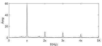
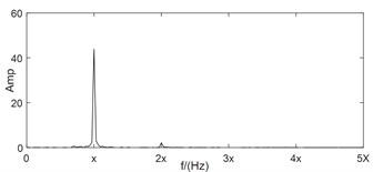
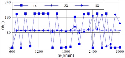
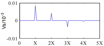
For large rotating machinery, two mutually perpendicular homologous vibration sensors are often arranged at the same section to monitor the operating status of the rotor more comprehensively. However, all of the above studies are based on the analysis of single channel vibration characteristic information. Firstly, the single channel vibration characteristic cannot fully reflect the true operating state of the rotor. Secondly, traditional single channel analysis methods ignore the internal connection between the two channels. Thirdly, the same source information in the two different channels often has significant differences in frequency structure and vibration amplitude. As shown in Fig. 1, the signals of two monitoring channels on the same section of a rotor in misaligned state are shown. In addition to obvious 1X, the -direction spectral characteristics also include 2X, 3X, etc., which complies with the characteristics of misaligned fault. But the -direction spectral characteristics only have obvious 1X features, which are consistent with the characteristics of unbalanced fault.
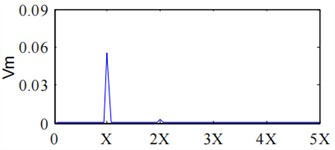
Fig. 1Case analysis of misalignment fault diagnosis based on full vector spectrum
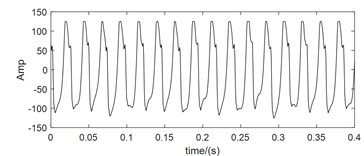
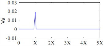
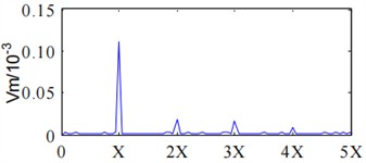
a)-direction time-domain waveform
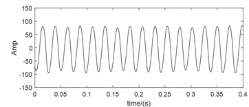
b)-direction time domain waveform
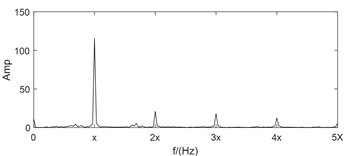
c)-direction frequency-domain waveform
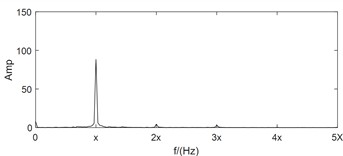
d)-direction frequency-domain waveform
e) Principle vibration vector
f) Auxiliary vibration vector
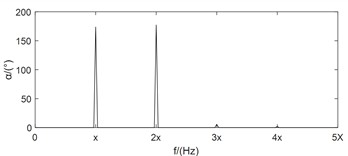
g) Vibration vector angle
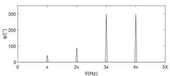
h) Vector phase
Compared with the feature layer information fusion method or the decision layer information fusion method, the same source information fusion method based on data layer not only solves the above mentioned drawbacks of the single channel analysis method, but also preserves the fault features in the original information to the greatest extent. Bently corporation in the United States proposed the full spectrum analysis method based on bidirectional information fusion of rotors with the same cross-section [12]. Academician Qu Liangsheng from Xi’an Jiaotong University proposed the holographic spectrum method for information analysis of rotating machinery [13]. The vibration research institute of Zhengzhou University proposed the full vector spectrum technology for homologous information fusion of rotating machinery [14]. The full vector spectrum technology inherits the idea of integrating full spectrum and holographic spectrum information, and improves the shortcomings of both. It has the advantages of simple numerical calculation, high resolution, comprehensive and intuitive reflection of information, feasibility of three-dimensional analysis, and good scalability [15]. Amounts of researches have been achieved based on full vector spectrum. The full vector spectrum was combined with empirical wavelet transform to improve the adaptability and accuracy of full vector spectrum, and the effectiveness of the proposed method was validated through two experimental cases [16]. A prediction model of vibration feature for equipment maintenance based on full vector spectrum was proposed, which provided a technical foundation for the fault prognostic research [17]. The traditional HHT was combined with full vector spectrum, and a new full vector HHT time domain marginal spectrum was proposed and used in fault diagnosis of crack of sliding bearing rotor system [18]. A fault diagnosis algorithm of rolling bearing based on full vector spectrum and frequency band entropy was proposed [19]. The traditional intelligent fault diagnosis system usually required a large amount of prior knowledge, and had the shortcomings of information loss caused by the incompleteness of single-channel signal. To solve these issues, a full-vector deep convolutional neural network diagnosis model for rolling bearing was proposed [20]. Here, taking the dual channel signals in Fig. 1 as example and after using the full vector spectrum technique to fuse them, the occurrence of the above misjudgment phenomenon is completely overcome, and the expressed feature information is more comprehensive and clear as following: the principle vibration vector spectrum is presented in Fig. 1(e), which reflects the characteristics of misalignment fault clearly such as typical 1X, 2X and 3X. Based on the auxiliary vector spectrum as shown in Fig. 1(f), it can be seen that there is a positive value at the power frequency, indicating that the rotor precesses in a positive direction at the power frequency, which further confirms the occuring of misalignment fault. The specific position of the rotor trajectory ellipse can be determined by the vibration vector angle as shown in Fig. 1(g), while the vector phase presented in Fig. 1(h) determines the initial phase of the rotor vortex. Therefore, the using of full vector spectrum technology not only provides clearer characteristic frequencies than traditional spectral analysis, but also reflects the vortex trajectory information of the rotor at various harmonic frequencies comprehensively and realistically, improving the reliability and accuracy of state monitoring and fault diagnosis greatly. The calculation process of the full vector spectrum technique is detailed in references [14-15], and it will not be repeated in the paper due to spatial limitations. Based on the above simulation analysis results, it can be seen that compared to the one sidedness of single channel information feature extraction method, which leads to inconsistent diagnostic conclusions, rotor fault feature extraction based on dual channel homologous information fusion technology can compensate for the shortcomings effectively.
In all, based on the current lack of specific mapping relationships between shaft vibration and bearing vibration information under the loose state of rotor support systems, as well as the advantages of dual channel homologous information fusion technology in rotor fault feature extraction, this paper conducts research on the mapping relationship between shaft vibration and bearing vibration under the loose state of rotor support based on full vector spectrum technology. The specific innovations are as follows:
1) A dynamic model of the rotor bearing foundation system under support loose state is established, which provides a model support for conducting related research.
2) The relationship between shaft vibration and bearing vibration at different speeds using full vector spectrum technology is analyzed, and the similarities and differences in the fault characteristics expressed by shaft vibration signals and bearing vibration signals under loose support fault are revealed systematically.
3) By mastering the revealed complementary relationship between shaft vibration and bearing vibration, the operating health status of equipment can be inferred based on the trend of some other key parameters even if in the absence of a certain measured signal, and corresponding maintenance and management measures can be formulated accordingly.
The remains of the paper are organized as following: section 2 is dedicated to the construction details of rotor dynamics model under support loose condition. Section 3 presents the simulation analysis of the relationship between shaft vibration and bearing vibration based on the constructed dynamic model. Discussion is given in Section 4 and conclusion is obtained in section 5 at last.
2. Construction of rotor dynamics model under loose support
Fig. 2 illustrates the construction of a dynamic model under support loose fault condition. In this model, denotes the center of the disk with a mass of 2. The shaft's stiffness and damping coefficients are represented by and , respectively. indicates the center of the shaft neck, which has a simplified mass of . The oil film forces acting on the journal center in the and directions are and . The center of bearing seat is at , and its equivalent mass is . The stator's stiffness coefficient is . The horizontal and vertical directions between the bearing seat and the base have stiffness and damping, and the corresponding coefficients are represented by , ,and , , respectively. The right end is the end where the support system is loose, and its stiffness coefficient and damping coefficient in the horizontal direction are and respectively, and the stiffness coefficient and damping coefficient in the vertical direction are and .
Fig. 2Dynamic model under support loose fault state
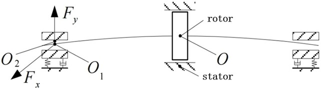
Assuming the displacements of the center of the disk in horizontal (-direction) and vertical (-direction) directions are represented by and respectively. The displacements of the center of the non-loosened end journal in the and directions are and . The displacement of the center of the non-loosened end bearing seat in the and directions are and . The displacements of the center of the loosened end journal in the and directions are and . The displacement of the center of the loosened end bearing seat in the and directions are and . The eccentricity of the disc is . The angular velocity of rotation is . If Capone’s short bearing oil film force model is used to describe the dynamic oil film force, the dynamic model of the rubbing rotor system, i.e. the system’s motion differential equations, can be expressed as following:
Convert Eq. (1) to one single dimension, i.e. let , , , , , , , , , , , , , , , , . Among themis eccentricity, is the bearing radius, is the viscosity of lubricating oil, is the length of the bearing, is the gravitational acceleration. is the normalized gravitational load.
Then, the Eq. (1) could be rewritten as following after normalization:
Due to the actual looseness fault of the support system, the looseness end has relatively small changes in the horizontal support stiffness and damping, mainly manifested in the vertical stiffness and damping changes. Therefore, assuming the stiffness and damping remain constant in the horizontal direction, only the changes in stiffness and damping in the vertical direction are considered. Due to the segmented changes in support stiffness and damping with the variation of clearance, the expressions for stiffness coefficient and damping coefficient in the vertical direction can be obtained as follows:
where is the clearance between the shaft vibration seat and the foundation.
3. Simulation analysis of the relationship between shaft vibration and bearing vibration under support loose fault
Simulate and analyze the rotor bearing system using Runge Kutta method between speeds of 600 r/min and 3000 r/min, and set the parameters as follows: = 30 kg, = 3.8 kg, = 60 kg, = 14 mm, = 48 mm, = 012 mm, = 2.6×10⁷N/m, = 2.4×10⁹N/m, = 6.5×10⁷N/m, = 3.0×10⁹N/m, = 2.7×10⁹N/m, = 950 N s/m, = 560 N s/m, = 360 N s/m, = 460 N s/m, = 500 N s/m, = 0.018 Pas, 9.811 N/kg.
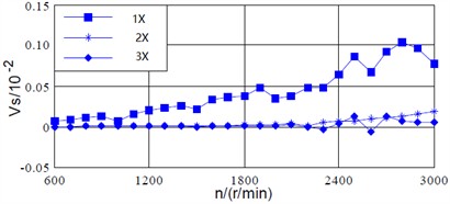
The variation curves of the principle vibration vector of the shaft vibration signal and the bearing vibration signal with respect to the rotational speed are shown in Fig. 3(a) and (b) respectively. As for the power frequency (1X), the principle vibration vectors of the shaft vibration signal and the bearing vibration signal both increase with the increasing of the speed, and the trend of their changes is also basically the same: the principle vibration vectors of the two kinds of signals are approximately linearly related to the speed. For the 2X, the principle vibration vector of the shaft vibration signal increases slowly with the increasing of speed, while the principle vibration vector of the bearing vibration signal changes approximately linearly with the increasing of speed until reaching 1800 r/min. There is a noticeable abrupt change between 1800 r/min and 2200 r/min, and the principle vibration vector increases with the increasing of speed above 2200 r/min. For the 3X, the trend of the principle vibration vector of the shaft vibration signal with respect to speed is similar to that of its 2X principle vibration vector, while the trend of the principle vibration vector of the bearing vibration signal is similar to that of its 2X principle vibration vector. Therefore, for the loosening fault of support system, the principle vibration vectors of the shaft vibration signal and the bearing vibration signal have a similar trend with the changing of speed. However, the principle vibration vector of the bearing vibration signal at 2X and 3X has a more obvious trend with the changing of speed, that is, the fault characteristics expressed by the bearing vibration signal are much clearer.
Fig. 3Principle vibration vectors of shaft and bearing signals with respect to varying speed
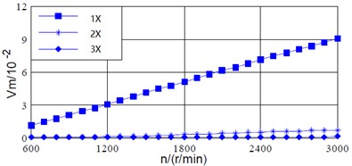
a) Principal vibration vector of shaft signal
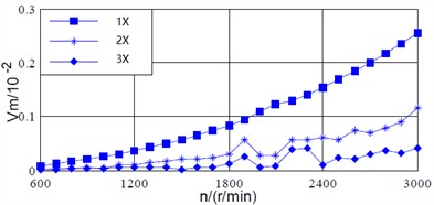
b) Principal vibration vector of bearing signal
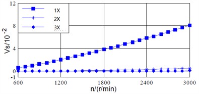
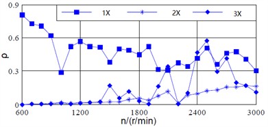
Fig. 4(a) and (b) show the variation curves of the auxiliary vibration vectors of the shaft vibration signal and the bearing signal with respect to the rotational speed. As for the power frequency (1X), the auxiliary vibration vector of the shaft vibration signal increases approximately linearly with the increasing of speed. Besides, its value is positive, indicating that the rotor’ precession direction is positive. However, the bearing vibration signal exhibits certain fluctuations, but the coaxial vibration signal can also reflect the precession direction of the rotor accurately. For the 2X, the values of the auxiliary vibration vectors for shaft vibration and bearing vibration are approximately 0 below 1500 r/min, indicating that the positive and negative precession components are equivalent. Although the values of both are positive above 1500 r/min, their changing trends differ significantly. For the 3X, the values of the shaft vibration signal is relatively small, while the values of the bearing vibration signal exhibits significant fluctuations with the increasing of speed above 2000 r/min, which is significantly different from the shaft vibration signal.
Fig. 5(a) and (b) show the variation curves of the vibration vector ratio between the two kinds of signals with respect to the rotational speed. As for the power frequency (1X), the vibration vector ratio of shaft vibration signal increases slowly with the increasing of speed, and it approximately changes linearly above 1800 r/min. However, the vibration vector ratio of bearing vibration signal generally decreases with the increasing of speed, which has a significant abrupt change phenomenon. Besides, the vibration vector ratio of shaft vibration signal is greater than that of bearing vibration signal above 900 r/min. For the 2X, the variation trend of the shaft vibration signal is similar to its power frequency, while the vibration vector ratio of the bearing vibration signal increases slowly with the increasing of speed. For the 3X, the values of shaft vibration signal is approximately 0 below 1200 r/min, and increases with the increasing of speed above 1200 r/min. The sudden change phenomenon of the bearing vibration signal is more obvious with the increasing of speed.
Fig. 4Auxiliary vibration vectors of shaft and bearing signals with respect to varying speed
a) Auxiliary vibration vector of shaft signal
b) Auxiliary vibration vector of bearing signal
Fig. 5Vibration vector ratio of shaft and bearing signals with respect to varying speed
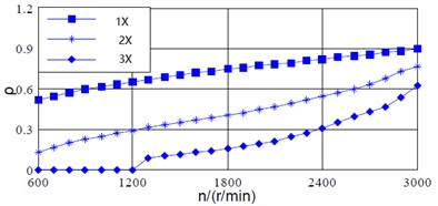
a) Vibration vector ratio of shaft signal
b) Vibration vector ratio of bearing signal
Fig. 6Vibration vector angel of shaft and bearing signals with respect to varying speed
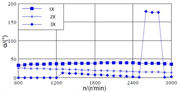
a) Vibration vector angle of the shaft vibration
b) Vibration vector angle of the bearing vibration
Fig. 6(a) and (b) show the variation curves of the vibration vector angle of the two kinds of signals with respect to the rotational speed. As for the power frequency (1X), the vibration vector angle of shaft signal changes slowly within the range of 33.5° to 38.9° with the increasing of speed, while there is a significant abrupt value change in the bearing vibration signal. For the 2X, the vibration vector angle of shaft vibration decreases slowly with the increasing of rotational speed, and it approximately changes linearly. The vibration vector angle of bearing vibration signal approximately changes linearly above 700 r/min, and varies between 90.2° and 94.4°. For the 3X, the vibration vector angle of shaft vibration signal varies approximately linearly between 600 r/min and 1200 r/min, 1300 r/min and 2500 r/min, while there is a sudden change phenomenon at other speeds. The bearing vibration signal varies approximately linearly between 700 r/min and 1900 r/min.
4. Discussion
At the speed of 1500 r/min, the full vector spectrum technique is used to discuss the fault characteristics of shaft vibration and bearing vibration under the support system loosening fault condition, as well as the similarities and differences in the fault characteristics expressed by the two kinds of signals.
From the spectrum of the shaft vibration signal presented in Fig. 7, it can be seen that both the principle and auxiliary vibration vectors of the shaft vibration signal are dominated by power frequency components, with a slight appearance at the second harmonic, but the amplitude is very small, indicating that the expressed fault characteristics are not very clear. From Fig. 8, it can be seen that fractional harmonics such as half harmonic and quarter harmonic, as well as higher harmonics such as two-thirds harmonic and second harmonic, are clearly expressed in the principle vibration vector spectrum, while the precession direction of the rotor at each harmonic frequency can be determined through the auxiliary vibration vector.
Fig. 7Full vector spectrum analysis results of shaft signal under 1500r/min
a) Principal vibration vector of shaft signal under 1500 r/min
b) Auxiliary vibration vector of shaft signal under 1500 r/min
Fig. 8Full vector spectrum analysis results of bearing signal under 1500 r/min
a) Principal vibration vector of bearing signal under 1500 r/min
b) Auxiliary vibration vector of bearing signal under 1500 r/min
Through comparative analysis, it can be seen that although the shaft vibration signal also exhibits certain fault characteristics such as second harmonic and other high-order harmonics, the fault characteristics of the bearing vibration signal are more obvious compared to others, especially when the full vector spectrum technology is used to fuse the dual channel information, the fused fault characteristics expressed are more comprehensive and clear.
5. Conclusions
This article proposes a simulation study on the relationship between shaft vibration and bearing vibration under support loose fault condition based on homologous information fusion. More accurate references can be provided for fault analysis and status monitoring by studying the relationship between them. The following conclusion could be obtained through systematic study:
1) As for the two kinds of signals, the fault characteristics expressed by the full vector spectrum are more real and reliable than single channel analysis results.
2) Under the loose fault of the support system, the principle vibration vectors of the shaft vibration signal and the bearing vibration signal have similar trends with the change of speed.
3) The fault characteristics of the bearing vibration signal are more obvious than those of the shaft vibration signal.
Although this study has achieved certain results, the established rotor system model is based on a rigid support system. However, the actual rotor bearing foundation system often has flexible supports due to its own structure and operational needs. Therefore, further research is needed on the relationship between shaft vibration and bearing vibration under different support properties.
In addition, there are many types of faults that occur in the rotor bearing foundation system, such as rotor misalignment, oil film oscillation, rotor cracks, etc. However, this article only analyzes and studies the common loosening fault occuring in the support system, which is obviously insufficient. Therefore, further in-depth research is needed on the relationship between shaft vibration and bearing vibration of the rotor bearing foundation system under other types of faults.
References
-
X. An and F. Zhang, “Pedestal looseness fault diagnosis in a rotating machine based on variational mode decomposition,” Proceedings of the Institution of Mechanical Engineers, Part C: Journal of Mechanical Engineering Science, Vol. 231, No. 13, pp. 2493–2502, Mar. 2016, https://doi.org/10.1177/0954406216637378
-
M. Jiang, J. Wu, X. Peng, and X. Li, “Nonlinearity measure based assessment method for pedestal looseness of bearing-rotor systems,” Journal of Sound and Vibration, Vol. 411, pp. 232–246, Dec. 2017, https://doi.org/10.1016/j.jsv.2017.09.002
-
M. Jiang, J. Wu, and S. Liu, “The influence of slowly varying mass on severity of dynamics nonlinearity of bearing‐rotor systems with pedestal looseness,” Shock and Vibration, Vol. 2018, No. 1, p. 37958, Feb. 2018, https://doi.org/10.1155/2018/3795848
-
M. Jiang, Y. Kuang, J. Wu, and X. Li, “Rub‐impact detection in rotor systems with pedestal looseness using a nonlinearity evaluation,” Shock and Vibration, Vol. 2018, No. 1, p. 79281, Nov. 2018, https://doi.org/10.1155/2018/7928164
-
M. Jiang et al., “Dynamic behaviors and assessment of loose-rubbing faults in rotor-sliding bearing system,” (in Chinese), Journal of Dynamics and Control, Vol. 15, No. 6, pp. 550–557, Nov. 2018, https://doi.org/10.6052/1672-6553-2017-38
-
G. Chen, “Nonlinear dynamic response analysis of rotor-ball bearing system including unbalance-rubbing-looseness coupled faults,” (in Chinese), Journal of Vibration and Shock, Vol. 27, No. 9, pp. 100–104, Oct. 2008, https://doi.org/10.13465/j.cnki.jvs.2008.09.007
-
G. Chen, “Rotor-ball bearing-stator coupling dynamic model including rubbing coupling faults,” Journal of Vibration Engineering, Vol. 20, No. 4, pp. 361–368, 2007.
-
G. Chen, “Nonlinear dynamics of unbalance-looseness coupling faults of rotor-ball bearing-stator coupling system,” Chinese Journal of Mechanical Engineering, Vol. 44, No. 3, p. 82, Jan. 2008, https://doi.org/10.3901/jme.2008.03.082
-
X. X. Qu, G. Chen, and B. D. Qiao, “Signal separation technology for dynamic model of rotor with unbalance-rubbing-looseness coupled faults,” (in Chinese), Journal of Vibration and Shock, Vol. 30, No. 6, pp. 74–77, Jul. 2011, https://doi.org/10.13465/j.cnki.jvs.2011.06.020
-
Y. Yang, Y. Yang, D. Cao, G. Chen, and Y. Jin, “Response evaluation of imbalance-rub-pedestal looseness coupling fault on a geometrically nonlinear rotor system,” Mechanical Systems and Signal Processing, Vol. 118, pp. 423–442, Mar. 2019, https://doi.org/10.1016/j.ymssp.2018.08.063
-
H. Li, M. Li, C. Li, F. Li, and G. Meng, “Multi-faults decoupling on turbo-expander using differential-based ensemble empirical mode decomposition,” Mechanical Systems and Signal Processing, Vol. 93, pp. 267–280, Sep. 2017, https://doi.org/10.1016/j.ymssp.2017.02.015
-
J. Y. Cao et al., “Diagnostic analysis of oil film induced rotor instability based on full spectrum plot technology,” (in Chinese), Journal of Jimei University, Vol. 25, No. 3, pp. 202–207, May 2020, https://doi.org/10.19715/j.jmuzr.2020.03.06
-
S. Liu and L. S. Qu, “Fault diagnosis prior the field balancing based on holospectrm,” (in Chinese), Journal of Vibration, Measurement and Diagnosis, Vol. 24, No. 4, pp. 270–274, May 2005, https://doi.org/10.16450/j.cnki.issn.1004-6801.2004.04.004
-
J. S. Qi and J. Han, “Research on sort of rotor misalignment based on coupled sections’ information fusion,” (in Chinese), Machinery Design and Manufacture, Vol. 9, p. 197, Oct. 2008, https://doi.org/10.3969/j.issn.1001-3997.2008.09.082
-
J. S. Qi, J. Han, and X. M. Dong, “Research on the same source information fusion of rotor’s multi-sections based on full vector spectrum analysis and fault diagnosis,” (in Chinese), Machinery Tool and Hydraulics, Vol. 36, No. 9, pp. 145–147, Sep. 2008, https://doi.org/10.3969/j.issn.1001-3881.2008.09.047
-
H. Yu, H. Li, Y. Li, and Y. Li, “A novel improved full vector spectrum algorithm and its application in multi-sensor data fusion for hydraulic pumps,” Measurement, Vol. 133, pp. 145–161, Feb. 2019, https://doi.org/10.1016/j.measurement.2018.10.011
-
L. Chen, J. Han, W. Lei, Z. Guan, and Y. Gao, “Prediction model of vibration feature for equipment maintenance based on full vector spectrum,” Shock and Vibration, Vol. 2017, pp. 1–8, Jan. 2017, https://doi.org/10.1155/2017/6103947
-
Y. P. Zhou et al., “Application of global vector spectrum in crack of sliding bearing rotor system,” (in Chinese), Machinery design and manufacture, Vol. 12, pp. 15–18, Dec. 2020, https://doi.org/10.19356/j.cnki.1001-3997.2020.12.004
-
W. P. Lei et al., “Fault diagnosis of rolling bearing based on FV-FBE,” (in Chinese), Journal of Zhengzhou University (Engineering Science), Vol. 41, No. 5, pp. 82–86, Sep. 2020, https://doi.org/10.13705/j.issn.1671-6833.2020.03.020
-
W. S. Hao et al., “Bearing fault diagnosis based on full vector-CNN,” (in Chinese), Journal of Zhengzhou University, Vol. 41, No. 5, pp. 92–96, Sep. 2020, https://doi.org/10.13705/j.issn.1671-6833.2020.03.004
About this article

This work was supported in part by the Key science and technology research project of the Henan province (Grant No. 252102221044), in part by the Youth Science and Technology Fund Project of China Minmetals Corporation (Grant No. 2024QNJJB15), in part by the Major R&D Project of the “181 Program” by China Metallurgical Group Corporation (Grant No. 2022ZY181A07), and in part by the Special Project Fund for Doctoral Innovation by China Fifth Metallurgical Group Co., Ltd (Grant No. WY2023C007).
The datasets generated during and/or analyzed during the current study are available from the corresponding author on reasonable request.
Dongliang Zou: conceptualization, funding acquisition, investigation, methodology, supervision, visualization, writing-review and editing. Hongchao Wang: data curation, formal analysis, project administration, resources, software, validation, writing-original draft preparation.
The authors declare that they have no conflict of interest.
