Abstract
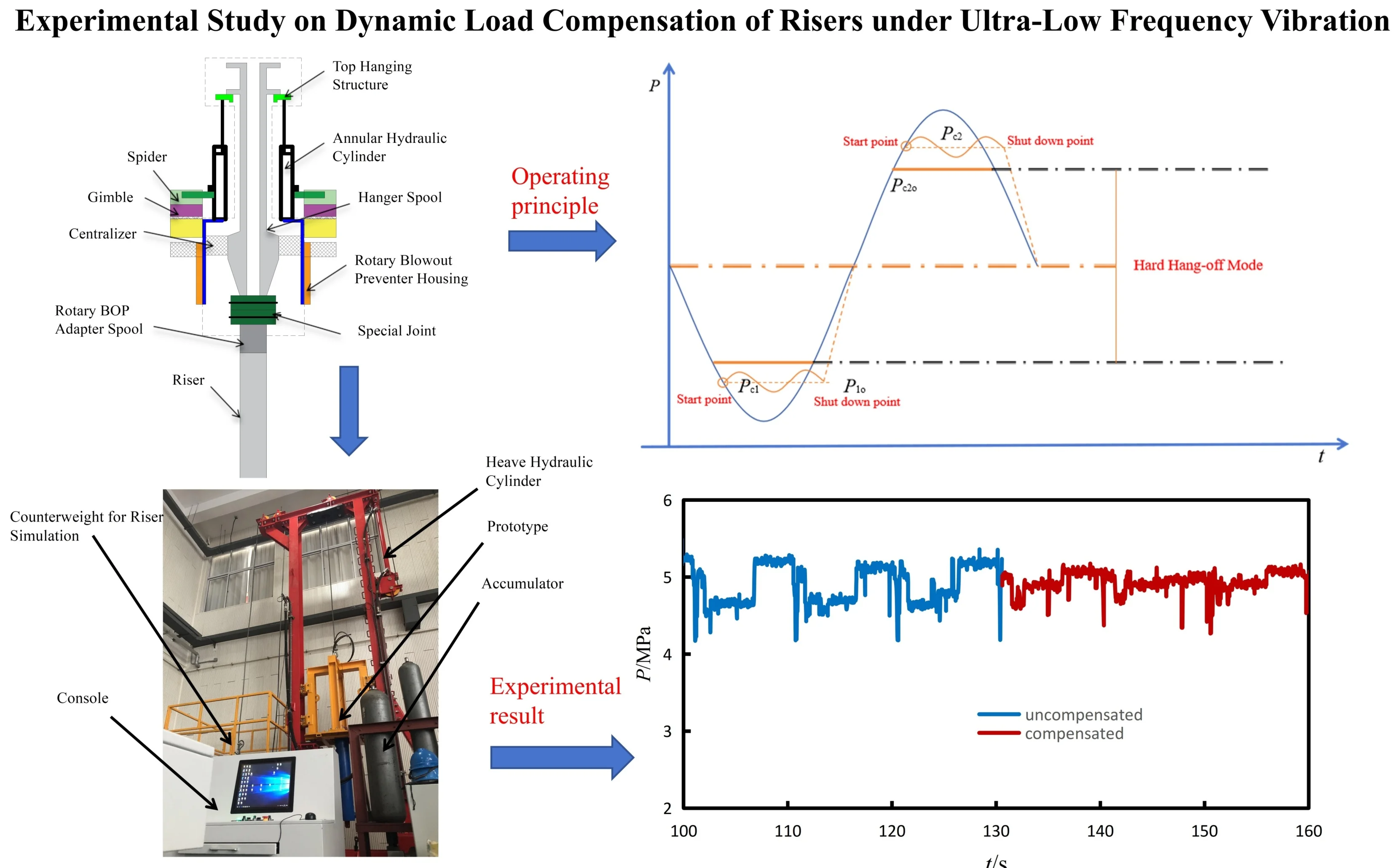
In the event that a floating drilling platform is struck suddenly by a typhoon, preventing the complete retrieval of the riser, a compensation system is required to alleviate the considerable dynamic loads on the riser resulting from platform movement, thus keeping the riser tension within safe limits. Evaluation of the mathematical model for the conventional vibration isolation system indicated unsatisfactory performance under conditions of large displacement and ultra-low-frequency vibration. To address this, a new dynamic load compensation system for the riser has been developed, along with a dedicated experimental platform. In this setup, platform heave is simulated via the extension and retraction of a hydraulic cylinder, while the riser load is represented using multiple mass blocks. The experimental platform supports both manual and automatic control modes. Utilizing Visual Basic (VB) programming integrated with an Access database, the monitoring and control software provides capabilities for parameter configuration, data monitoring, and data archiving. Experiments performed on this platform, including heavy simulation and dynamic load compensation, demonstrated a compensation effect of 27.4 %. The successful mitigation of dynamic loads on the riser presents a novel approach for drilling platforms to cope with typhoon emergencies and suggests valuable applications for vibration isolation technology in other domains.
Highlights
- A new type of dynamic load compensation system for riser is proposed and the corresponding structure and control principle are described.This system can also provide a certain level of vibration isolation for ultra-low frequency and large amplitude vibrations.
- A new experimental device for dynamic load compensation of riser has been designed, and it has been verified through experiments to have a good simulation function for heave motion.
- Through the load compensation experiment, it is shown that the load compensation system can effectively reduce the load of riser, so as to reduce the tension range of riser during the platform operation, and the load compensation effect can reach 27.4%.
1. Introduction
When an offshore floating drilling platform is threatened by a typhoon, limitations in typhoon forecasting and the rapid onset of such storms often make it impossible to fully retrieve the entire riser string before evacuation. In such scenarios, a portion of the riser must be left suspended in the water column for emergency shelter [1-2]. Currently, two primary methods are used for hanging the riser. One involves a rigid connection between the riser and the platform, utilizing a chuck and universal joints; this configuration results in the riser moving integrally with the platform, fully subjected to wave-induced motions. The other method employs a tensioner, which utilizes its long compensation stroke to maintain the tension within the riser.
In view of the dynamic response of risers, considerable research has been conducted by scholars worldwide. Akorede et al. [5] investigated the viability of reusing a drilling riser in disconnected mode when drilling resumes after a typhoon. Rizwan et al. [6] analyzed the vibration of suspended risers under random ocean current loads and assessed the resulting fatigue damage. Orest et al. [7] developed an improved mathematical model for the axial and lateral vibrations of risers, enabling the study of stress-strain states and top tension under sea surface conditions. Mao et al. [8-9] performed a dynamic analysis of drilling risers under both normal drilling and hang-off conditions, examining the influence of current velocity, platform motion trajectory, and suspended riser length on the top bending moment and deformation during platform evacuation. Liu et al. [10-11] established a coupled model of a divider system and a tensioner, analyzing the dynamic characteristics of the divider under different operational states. Their results indicated that the tensioner’s inhibitory effect can reduce the dynamic displacement of the divider; they also developed an experimental platform for dynamic control of marine drilling riser suspension. Xu et al. [12] designed a novel specialized soft suspension system to improve the adaptability of drilling riser systems during suspended or transit operations. Song et al. [13] employed finite element simulations to analyze the mechanical properties of suspended risers and proposed a new optimization method for platform navigation between adjacent wells.
In the broader field of vibration isolation, Layinde et al. [14] explored vibrational resonance in a Duffing-type isolation system using analytical and numerical approaches, demonstrating that the response amplitude under low-frequency excitation can be enhanced by modulating system parameters, particularly under dual-frequency excitation and with nonlinear stiffness. Zheng et al. [15] proposed a six-degree-of-freedom quasi-zero-stiffness isolation platform comprising six modules based on compressed-spring structures, explaining the underlying quasi-zero-stiffness principles in both translational and torsional directions. Jurevicius et al. [16] developed a passive mechanical vibration isolation system with quasi-zero-stiffness properties, which effectively isolates low-frequency vibrations through a specially designed elastic structure and damping mechanism. Rashed et al. [17] evaluated the seismic response of high-speed railway bridges equipped with tuned mass dampers (TMDs) by analyzing their fragility curves. Zhu et al. [18] presented an active meta-plate consisting of a host plate and a periodic array of local resonators that can be collectively and actively tuned using stepping motors; this configuration achieves real-time active vibration suppression with only a small number of active components.
At present, most studies on riser dynamics focus on their behavior under conventional suspended conditions. The primary strategy involves modifying the riser configuration and the platform’s navigation methods to avoid typhoon impacts. Additionally, variable damping shock isolators commonly used in vehicle vibration reduction or building seismic isolation are mainly designed for medium- to high-frequency, small-amplitude vibrations. These devices are not yet fully suitable for the ultra-low-frequency, large-amplitude vibrations typical of drilling platform conditions. Consequently, this study introduces an improved suspension scheme for the riser. To address the characteristic large-amplitude, ultra-low frequency motions of the platform, a dynamic load compensation method was proposed. A corresponding experimental platform was also designed to validate the feasibility of the proposed scheme.
2. Introduction to the principle of dynamic load compensation for risers
2.1. Analysis of traditional vibration isolator
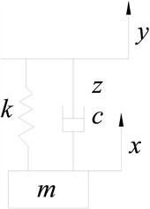
The motion of the riser coupled with the platform can be characterized as an ultra-low-frequency vibration. Consequently, dynamic load compensation methods for the riser can be effectively analyzed from a vibration reduction perspective. To facilitate theoretical analysis, the riser is modeled as an equivalent mass block to assess the feasibility of these compensation methods. The traditional vibration isolation is represented by a spring-mass-damper system, as illustrated in Fig. 1. The displacement of the riser is set to , the platform displacement is , the isolator displacement is , the isolator stiffness is , and the isolator damping is .
Based on the aforementioned model, the differential equation of motion is derived as Eq. (1). Assuming the platform undergoes sinusoidal motion, its kinematic equation is given by Eq. (2):
where the is the amplitude of platform displacement, the is the angular velocity of platform motion.
Fig. 1Vibration isolation mechanical model
The displacement response of the riser, formulated in Eq. (3), is derived by solving the system of equations after substituting Eq. (2) into Eq. (1):
where is amplitude of the displacement of the riser, is steady-state phase difference of the displacement of the riser, is frequency ratio, is damping ratio.
The relationship between the displacement amplitude ratio of the riser relative to the platform and the system frequency ratio, under different damping ratios calculated from Eq. (3), is presented in Fig. 2. As shown in Fig. 2, the variation of the amplitude ratio with the damping ratio is characterized by an initial increase followed by a decrease, asymptotically approaching zero, with all curves intersecting at 1.414 and an amplitude ratio of 1. Only by reducing the intensity of the displacement vibration of the riser can a certain degree of compensation for the dynamic load of the riser be achieved. Therefore, it is required that the amplitude ratio of the displacement between the riser and the platform be less than 1. It can be seen from the Fig. 2 that when the damping ratio is within the range of 0 to 1, the system can only meet the above requirements when 1.414.
The displacement of the riser () is the superposition of the vibration isolator’s displacement () and the platform’s displacement (), i.e., . Substituting this kinematic relation into Eq. (3) and solving yields the steady-state response of the vibration isolator, as given in Eq. (4):
where is vibration response of the isolator, is amplitude of the isolator displacement.
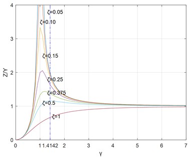
The relationship between the displacement amplitude ratio of the isolator relative to the platform and the system frequency ratio, as determined from Eq. (4) for different damping ratios, is presented in Fig. 3. As shown in Fig. 3, the amplitude ratio increases first and then decreases as the damping ratio increases, ultimately tending toward 1. A key observation is that the amplitude ratio exceeds 1 for all damping ratios when 1.414. This condition necessitates an isolator stroke greater than the platform’s heave displacement.
Due to the limitations of the platform space and installation requirements, the maximum compensation stroke is 2.4 meters, that is, the vibration amplitude of the vibration isolator is 1.2 meters. According to the above analysis results, the flexible suspension can only play a dynamic load compensation role when the platform’s heave amplitude must be less than 1.2 meters. However, the uplift amplitude of the platform is 4.55 m, so the traditional vibration isolators cannot meet the requirements.
Fig. 2X/Y relative to the frequency ratio for different damping ratios
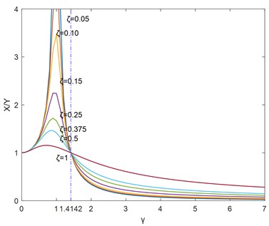
Fig. 3Z/Y relative to the frequency ratio for different damping ratios
2.2. The new type of dynamic load compensation system for riser
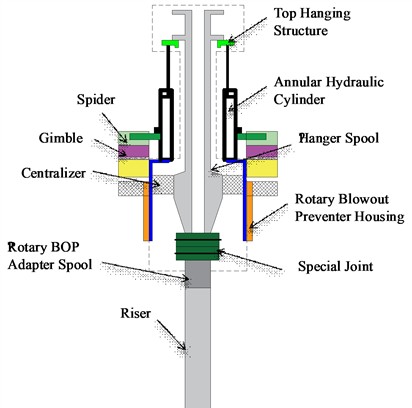
The configuration of the dynamic load compensation device for the riser is illustrated in Fig. 4. The annular hydraulic cylinder is integrated with the riser joint and seated on the spider. The riser joint is connected to the riser string via a rotary table transition adapter. A centralizer housed inside the rotary table assembly counteracts lateral forces, ensuring the riser joint maintains strictly vertical movement.
The annular hydraulic cylinder acts as the primary actuator for dynamic load compensation. Through its precisely controlled motion, it partially offsets the dynamic loads transmitted through the riser system induced by platform motion.
Fig. 4Riser dynamic load compensation device
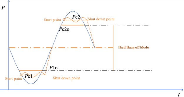
The principle of dynamic load compensation control of the riser is shown in Fig. 5. Start of the principle prototype of the dynamic load compensation system of the riser: the analog signal provided by the pressure sensor and the displacement sensor is obtained by the central control system, The compensated cylinder pressure and piston displacement, And derive deviation by comparison with the given pressure and displacement signals, And then passed to the controller according to the magnitude of the difference, Thus to complete the control of the flexible suspension, The device on when the detected pressure exceeds the set control pressure range, Start the compensation movement. Pressure signal comparison is shown in Eq. (5) and Eq. (6). The dynamic load compensation system stops: when the detected pressure is within the set control pressure range, If the piston rod relative speed is 0, stop the moving load compensation (piston rod lock).
Up stroke:
Down stroke:
where and compensate the ideal control pressure for the upper and down strokes of the hydraulic cylinder respectively, and and are the actual control pressure for the up and down strokes respectively.
Fig. 5Compensated hydraulic cylinder pressure control curve
Set as the opening of the throttle valve, for the dead area when the piston travels up, and for the dead area of the hydraulic system when the piston travels down. The throttle valve base opening degree is Eq. (7):
where the is the proportional gain, the is the integral time constant, the is the differential time constant, and the is the quality of the water divider system.
The deviation is given by Eq. (8):
Therefore, the throttle opening calculation formula is given by Eq. (9):
To limit the maximum opening and saturation phenomenon of the throttle valve during the control process, the restriction mode is given by Eq. (10):
where is the maximum opening of the throttle on the piston rod, and is the maximum opening of the throttle under the piston rod.
In order to improve the stability of the system control and avoid the compensation cylinder, the pressure can correct the desired pressure with the position of the piston in the hydraulic cylinder, adjust the pressure expectation by using the controller, and the desired pressure correction formula is Eq. (11) and Eq. (12), respectively:
where is the position of the piston in the cylinder, is the lower piston control position, and is the upper piston control position.
3. Experimental platform design
3.1. Mechanical structure design
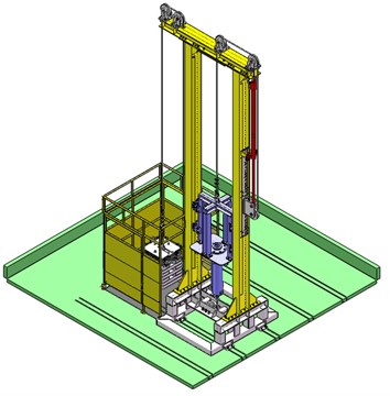
The structure of the experimental platform for the riser dynamic load compensation system is illustrated in Fig. 6. The apparatus is primarily composed of four subsystems: a load (riser) simulation system, a heave simulation system, a prototype compensation mechanism, and auxiliary components (e.g., wire ropes, support frames, and various safety protection devices).
Considering the height constraints of the laboratory site, the load simulation system employs a stacked configuration of multiple mass blocks. The heave simulation system is driven by the vertical motion of a hydraulic cylinder combined with a pulley mechanism mounted on the platform. The prototype compensation mechanism comprises a compensating hydraulic cylinder, an annular cylinder, a suspended short segment, and a lifting hanger, which collectively realize the function of dynamic load compensation.
The load is wound to the bottom end of the annular cylinder via the two pulleys mounted on the base of the support frame. The annular cylinder is fixed to the bottom of the hanger by a front flange. The top of the hanger is connected to a wire rope, which is wound to the bottom end of the lifting cylinder through two pulleys and an additional pulley attached to the front end of the lifting cylinder’s piston. To ensure stable lifting and heave motion of the annular cylinder, two sets of V-shaped guide wheels are installed on both sides of the annular cylinder hanger to prevent shaking during movement. The experimental platform has a load capacity of 2.3 t, a total height of 7.5 m, and occupies a floor area of 3.8 m×2 m.
Fig. 6Structure diagram of experimental platform
3.2. Hydraulic system design
The hydraulic system primarily comprises a simulated hydraulic system and a principle prototype hydraulic system. The schematic of the hydraulic system is illustrated in Fig. 7. As shown on the right side of Fig. 7, the heave simulation hydraulic system includes the following main hydraulic components: a heave hydraulic cylinder, an electromagnetic proportional directional control valve, a plunger pump, an electric motor, a quick-closing valve, a relief valve, and a hydraulic oil tank. The heave hydraulic cylinder is equipped with both a pressure sensor and a displacement sensor. This heave simulation system operates under active control.
Fig. 7Experimental platform hydraulic system schematic diagram: 1 – oil tank, 2 – plunger pump, 3 – motor, 4 – relief valve, 5 – quick closing valve, 6, 11 – pressure sensor, 7 – temperature sensor, 8 – accumulator, 9 – throttle valve, 10 – control unit, 12 – displacement sensor, 13 – load(riser), 14 – annular cylinder, 15 – heave cylinder, 16 – electromagnetic proportional directional control valve
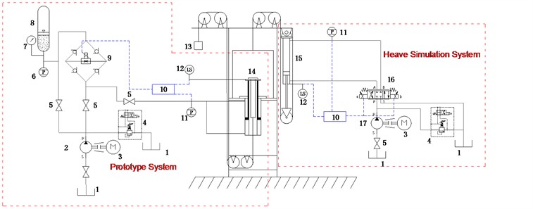
The plunger pump serves as the sole power source for the experimental platform. The control unit drives the heave hydraulic cylinder by regulating the direction and opening of the proportional directional valve. Based on closed-loop feedback from the displacement sensor, the heave hydraulic cylinder moves up and down according to a predefined motion profile, thereby simulating the heave motion and driving the principle prototype system accordingly.
The hydraulic system of the principle prototype primarily consists of an annular cylinder, a proportional throttle valve block, an accumulator, and pressure and temperature sensors, as illustrated in the left section of Fig. 7. The annular cylinder is configured in a fully differential connection mode, meaning that both the upward and downward compensation strokes operate under differential conditions. The throttle valve employs a bridge-circuit structure, enabling bidirectional flow control with a single valve unit. Furthermore, the system incorporates a segmented variable damping control strategy to enhance regulation performance.
During the upward stroke of the compensating hydraulic cylinder, the riser is subjected to a dynamic load oriented opposite to the direction of gravity. As a result, the load borne by the hydraulic cylinder reaches its minimum value. In this phase, the accumulator operates in an energy-release state: hydraulic oil flows from the accumulator through the throttle valve, driving the riser upward. The control unit adjusts the opening of the throttle valve to maintain a constant pressure in the hydraulic cylinder, thereby stabilizing the dynamic load on the riser throughout the upward stroke. Conversely, during the downward stroke, the dynamic load on the riser acts in the same direction as gravity. Consequently, the load exerted on the hydraulic cylinder attains its maximum value. Here, the accumulator functions in an energy-storage state, as the riser motion forces oil from the hydraulic cylinder back to the accumulator via the throttle valve. Similarly, the throttle valve opening is regulated to maintain a consistent pressure in the compensating hydraulic cylinder, ensuring a stable dynamic load during the downward stroke. This control strategy achieves the objective of reducing the peak dynamic load on the riser, enhancing the safety and stability of the system under varying operational conditions.
The prototype hydraulic system is connected to the power source of the heave simulation hydraulic system. By switching the operational state of the valves, the prototype system can be powered or replenished when the heave simulation system is inactive.
3.3. Control system design
3.3.1. Overall structure of the electrical system
The control system of the main dynamic load compensation system adopts a Distributed Control System (DCS) architecture, with an Industrial Personal Computer (IPC) serving as the monitoring and control center. The system incorporates components such as acquisition cards, amplification circuit boards, and a power management module. Communication between the IPC and the acquisition cards is implemented via a PCI bus, enabling parameter monitoring and real-time control functions. The overall structure of the electronic control system is illustrated in Fig. 8.
Fig. 8Overall structure of electric control system
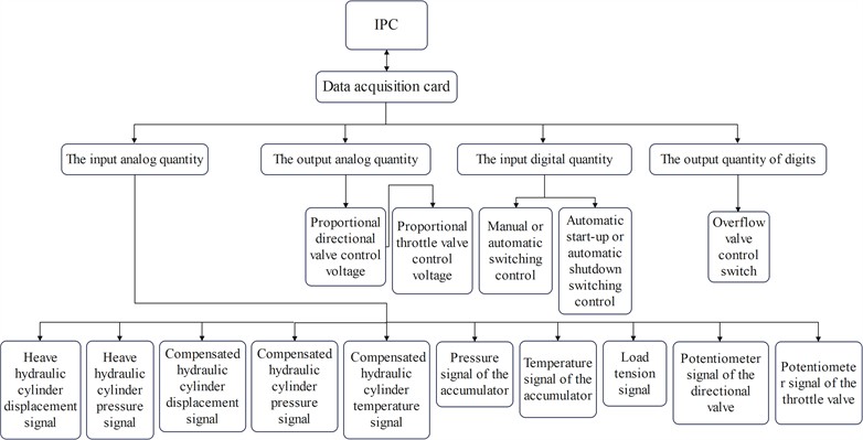
The Industrial Personal Computer (IPC) converts analog signals from various sensors, which are acquired via the data acquisition card, into actual data in real time. This process enables continuous monitoring of the motion states of both the heave simulation system and the prototype system. Simultaneously, operators can send control commands to the control module by adjusting relevant parameters within the control software. Key controlled components include the heave hydraulic cylinder, compensation hydraulic cylinder, electromagnetic proportional directional valve, electromagnetic proportional throttle valve, and electromagnetic relief valve, among others.
The electrical control system is primarily composed of three functional modules: the drive module, detection module, and control module. The drive module mainly consists of the drive motor. The detection module incorporates multiple sensors, such as a magnetostrictive linear displacement sensor for measuring riser and heave displacement, a laser displacement sensor for compensation displacement detection, as well as pressure sensors for the heave cylinder, compensating cylinder, and accumulator, in addition to a temperature sensor. The control module includes an industrial control computer (IPC), a multi-function data acquisition card, a hydraulic valve drive amplifier, and an AC-DC power supply module.
3.3.2. Monitoring system design
The control software for the experimental platform was developed using Visual Basic 6.0 in combination with Access. Visual Basic is an object-based visual programming language known for its powerful functionality and ease of learning [19]. Access is a database system commonly employed in software development and related fields, and it can be effectively integrated with Visual Basic [20]. The interface of the experimental control software is shown in Fig. 9.
Fig. 9Control software interface
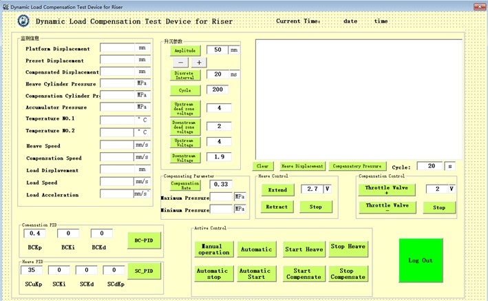
The software enables the monitoring, parameter setting, graphical display, and data storage for the experimental platform of the riser load compensation system. Monitoring information includes motion parameters such as riser displacement, heave displacement, and compensated displacement, as well as pressure data from the heave hydraulic cylinder, compensating hydraulic cylinder, and accumulator. Configurable parameters encompass displacement amplitude, period, controller selection, PID gain, quantization factor, and proportional factor. The curve display function visualizes heave displacement and compensation pressure. All monitored data and parameters can be stored for subsequent experimental analysis.
4. Experimental platform design
The sedimentation simulation experiment and dynamic load compensation experiment were completed on the experimental platform, which is shown in Fig. 10. The experimental platform parameters were set based on similarity principles, scaled at a 1:3 ratio relative to the engineering prototype parameters. PID parameters were configured according to system simulation results. Experimental platform parameters are listed in Table 1.
Fig. 10Riser dynamic load compensation experimental platform. Photo by Zhikun Wang, June 15, 2023, in Qingdao, P. R. China
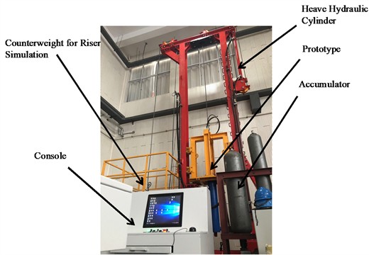
Table 1Experimental platform parameters
Keyword Parameter | Value |
Heave amplitude / m | 1.52 |
Period / s | 8 |
Compensate hydraulic cylinder’s stroke / mm | 800 |
Load mass / t | 2.3 |
Accumulator volume / L | 71 |
Heave system PID parameters | = 20, = 0.1, = 0.05 |
Compensation system PID parameters | = 35, = 0.1, = 0.03 |
4.1. Seaboard simulation experiments
The period was set to 8s, and the simulation experiment with the ascending and ascending amplitude gradually increased, and the experimental results are shown in Fig. 11.
Fig. 11Heave simulation experiment
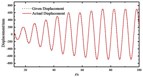
It can be seen from the figure that the actual detected displacement curve after setting the PID parameter basically coincides with the given displacement curve, which proves that it has good heave simulation function in the experimental platform.
4.2. Dynamic load compensation experiment
4.2.1. Single-trip dynamic load compensation experiment
To ensure experimental safety, a single-trip dynamic load compensation test was conducted. The method involves setting the lower and upper pressure limits for the compensated hydraulic cylinder, with the accumulator pressure configured to be higher and lower than that of the cylinder, respectively.
During the upward trip dynamic load compensation experiment, the throttle valve was closed, and the accumulator was charged to a pressure exceeding the static equilibrium pressure of the compensated hydraulic cylinder. If the pressure in the hydraulic cylinder dropped below the set minimum limit, hydraulic oil flowed from the accumulator into the cylinder to maintain the pressure at the predefined minimum level.
Similarly, during the downward trip dynamic load compensation experiment, the accumulator pressure was released to a value below the static equilibrium pressure of the compensated hydraulic cylinder. When the pressure in the cylinder exceeded the set maximum limit, the prototype system was activated: the control throttle valve opened, allowing hydraulic oil to flow into the accumulator, thereby reducing the cylinder pressure and maintaining it at the prescribed maximum value.
Fig. 12Dynamic load compensation experiment
a) Upstroke dynamic load compensation experiment
b) Downstroke dynamic load compensation experiment
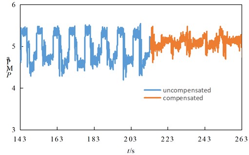
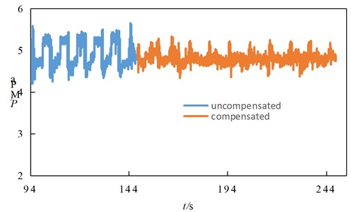
The upward-stroke dynamic load compensation was tested first, and the measured pressure of the compensated hydraulic cylinder is shown in Fig. 12(a). As can be observed, the minimum pressure of the compensated hydraulic cylinder increased from 4.73 MPa before compensation to approximately 4.93 MPa after compensation was activated, corresponding to a pressure increase of 0.20 MPa. Similarly, the compensation of the upper pressure limit was tested, and the resulting pressure of the compensated hydraulic cylinder is presented in Fig. 12(b). The results show that the maximum pressure decreased from 5.35 MPa before compensation to about 5.16 MPa after compensation, representing a pressure reduction of roughly 0.19 MPa. These unilateral stroke compensation experiments verify the effectiveness of the prototype system. Subsequent tests will be conducted over the full stroke using different control algorithms for further evaluation.
4.2.2. Full-trip dynamic load compensation experiment
The PID control for the dynamic load compensation prototype of the riser is implemented in discrete form and executed directly by the host computer control software. Based on the preceding experimental study, the uncompensated pressure fluctuation range of the compensated hydraulic cylinder was found to be between 4.73 MPa and 5.35 MPa. To maintain a roughly consistent pressure differential across the throttle valve, the accumulator was initialized to 5 MPa with a pre-charge pressure of 3.5 MPa, and the preset pressure limits were set to 4.63 MPa (lower) and 5.13 MPa (upper), respectively. The experimental results are presented in Fig. 13.
Fig. 13Full range dynamic load compensation experiment
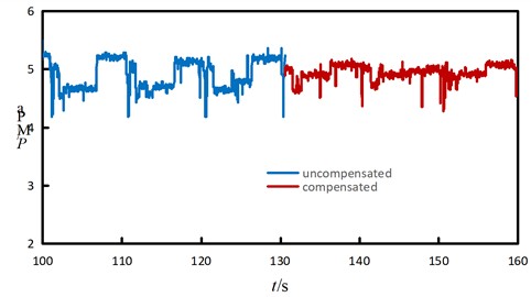
As shown in Fig. 13, during PID-controlled compensation, the maximum cylinder pressure decreased from 5.35 MPa to 5.14 MPa, while the minimum pressure increased from 4.18 MPa to 4.27 MPa. Consequently, the pressure fluctuation range of the compensated cylinder was reduced from 1.17 MPa to 0.85 MPa, corresponding to a 27.4 % reduction in dynamic load.
5. Conclusions
Analysis of the conventional vibration isolation model shows that a sufficient compensation stroke is essential for achieving effective vibration isolation. To address the limitation of insufficient actual compensation travel, a novel method for compensating the dynamic load of the riser is proposed, and a corresponding experimental apparatus is designed for validation. The following conclusions are drawn:
1) An experimental platform for dynamic load compensation was developed, incorporating the complete design of the mechanical, hydraulic, and control systems. Experimental investigations into the dynamic load compensation performance were carried out.
2) Heave simulation experiments demonstrate that the actual displacement curve closely aligns with the predefined displacement curve, indicating that the platform exhibits excellent heave simulation capability.
3) Load compensation experiments confirm that the proposed system effectively reduces the dynamic load on the riser, thereby decreasing the tension range during platform operations, with a compensation effectiveness of 27.4 %. These findings offer valuable insights for vibration isolation applications in other fields.
References
-
X. L. Dong, “Research progress and prospect for serious accident prevention and control technology of deep water drilling,” (in Chinese), China Offshore Oil and Gas, Vol. 30, No. 2, pp. 112–119, Apr. 2018, https://doi.org/10.11935/j.issn.1673-1506.2018.02.016
-
X. Liu et al., “Analyses and countermeasures of deepwater drilling riser grounding accidents under typhoon conditions,” (in Chinese), Petroleum Exploration and Development Online, Vol. 40, No. 6, pp. 791–795, Dec. 2013, https://doi.org/10.11698/ped.2013.06.14
-
L. X. Sheng et al., “Safety analysis of the hang-off of deepwater drilling risers during a typhoon emergency period,” (in Chinese), Petroleum Drilling Techniques, Vol. 43, No. 4, pp. 25–29, Jul. 2015, https://doi.org/10.11911/syztjs.201504005
-
L. B. Xu et al., “Analysis of deep water drilling platform evacuation from imminent typhoons with riser hanging-off in the South China Sea,” (in Chinese), China Offshore Oil and Gas, Vol. 27, No. 3, pp. 101–107, Jun. 2015, https://doi.org/10.11935/j.issn.1673-1506.2015.03.016
-
F. A. Abimbola, J. Yang, S. Liu, and T. Sun, “Survivability study of deepwater drilling riser in freestanding mode,” Ocean Engineering, Vol. 222, No. 1, p. 108634, Feb. 2021, https://doi.org/10.1016/j.oceaneng.2021.108634
-
R. A. Khan and S. Ahmad, “Dynamic response and fatigue reliability analysis of marine riser under random loads,” in 26th International Conference on Offshore Mechanics and Arctic Engineering, pp. 183–191, Jan. 2007, https://doi.org/10.1115/omae2007-29235
-
O. Slabyi, “Studying the coupled axial and lateral oscillations of the drilling riser under conditions of irregular seaways,” Eastern-European Journal of Enterprise Technologies, Vol. 3, No. 7 (93), pp. 27–33, May 2018, https://doi.org/10.15587/1729-4061.2018.132661
-
L. Mao, S. Zeng, and Q. Liu, “Dynamic mechanical behavior analysis of deep water drilling riser under hard hang-off evacuation conditions,” Ocean Engineering, Vol. 183, pp. 318–331, Jul. 2019, https://doi.org/10.1016/j.oceaneng.2019.05.014
-
L. Mao, S. Zeng, Q. Liu, G. Wang, and Y. He, “Dynamical mechanics behavior and safety analysis of deep water riser considering the normal drilling condition and hang-off condition,” Ocean Engineering, Vol. 199, No. 2, p. 106996, Mar. 2020, https://doi.org/10.1016/j.oceaneng.2020.106996
-
X.-Q. Liu et al., “Mechanical analysis of deepwater drilling riser system based on multibody system dynamics,” Petroleum Science, Vol. 18, No. 2, pp. 603–617, Oct. 2020, https://doi.org/10.1007/s12182-020-00506-1
-
X. Q. Liu, Y. W. Li, and X. L. Wang, “Development of experimental platform for hang-off dynamics control of offshore drilling risers,” (in English), Experimental Technology and Management, Vol. 40, No. 6, pp. 168–186, Jun. 2023, https://doi.org/https://doi.org/
-
L. Xu et al., “Development and sea trial investigation for deepwater drilling riser specialized soft hang-off system during transit,” Ocean Engineering, Vol. 243, p. 110310, Jan. 2022, https://doi.org/10.1016/j.oceaneng.2021.110310
-
Y. Song, J. Yang, and B. Zhou, “Optimal route design of adjacent wells and mechanical properties of hang-off drilling riser in ocean environment,” International Journal of Environmental Science and Technology, Vol. 16, No. 9, pp. 5073–5078, Sep. 2018, https://doi.org/10.1007/s13762-018-2006-2
-
T. O. Roy-Layinde, K. A. Omoteso, J. A. Laoye, and U. H. Diala, “Vibrational resonance in nonlinear vibration isolation systems,” Mechanics Research Communications, Vol. 148, p. 104470, Sep. 2025, https://doi.org/10.1016/j.mechrescom.2025.104470
-
Y. Zheng, X. Zhang, Y. Luo, S. Xie, and Y. Zhang, “Harnessing the compressed-spring mechanism for a six-degrees-of-freedom quasi-zero-stiffness vibration isolation platform,” Journal of Vibration and Control, Vol. 27, No. 15-16, pp. 1793–1805, Aug. 2020, https://doi.org/10.1177/1077546320948399
-
M. Jurevicius, V. Vekteris, G. Viselga, V. Turla, A. Kilikevicius, and I. Iljin, “Dynamic research on a low-frequency vibration isolation system of quasi-zero stiffness,” Journal of Low Frequency Noise, Vibration and Active Control, Vol. 38, No. 2, pp. 684–691, Feb. 2019, https://doi.org/10.1177/1461348419830295
-
P. Rashed, I. Nayel, V. Broujerdian, and E. Zafarkhah, “Probabilistic seismic performance assessment of high-speed railway bridge with tuned mass dampers,” Advances in Bridge Engineering, Vol. 6, No. 1, pp. 26–26, Jul. 2025, https://doi.org/10.1186/s43251-025-00173-5
-
Z. Zhu et al., “Auto-adaptive metastructure for active tunable ultra-low frequency vibration suppression,” International Journal of Mechanical Sciences, Vol. 271, p. 109131, Jun. 2024, https://doi.org/10.1016/j.ijmecsci.2024.109131
-
X. Li and L. Z. Wang, “Design of hydraulic cylinder integrated property automatic detection system based on VB,” (in Chinese), MACHINE TOOL and HYDRAULICS, Vol. 41, No. 14, pp. 100–102, Jul. 2013, https://doi.org/10.3969/j.issn.1001-3881.2013.14.035
-
X. F. Cheng and P. B. Lin, “Construction of adaptable design platform for bridge crane based on VB/CAE/Access interfaces,” (in Chinese), Journal of Machine Design, Vol. 34, No. 9, pp. 54–58, Sep. 2017, https://doi.org/10.13841/j.cnki.jxsj.2017.09.011
About this article

The authors gratefully acknowledge the financial support of Doctoral Research Initiation Fund Project of Qingdao Huanghai University (Project No. 2023boshi01), Key R&D Program of Shandong Province, China (Project No. 2022CXGC020402), the Fundamental Research Funds for the Central Universities (Project No. 25CX02017A), the Independent R&D Fund of National Engineering Research Center of Marine Geophysical Prospecting and Exploration and Development Equipment (Project No. 25CX02017A).
The datasets generated during and/or analyzed during the current study are available from the corresponding author on reasonable request.
Zhikun Wang: investigation, software, methodology, validation, supervision, funding acquisition and writing-original draft. Fengmei Zhang: investigation, methodology, writing-review and editing. Lumeng Huang: conceptualization, software, methodology, validation, project administration, writing-original draft, writing-review and editing.
The authors declare that they have no conflict of interest.
