Abstract
The production and distribution of electrical energy remain among the most pressing challenges in modern power supply systems. To address this issue, the integration of renewable energy sources and the use of asynchronous generators in mini- and micro-hydroelectric power plants are being actively developed. Asynchronous generators possess several advantages over synchronous machines, including structural simplicity, operational reliability, and low manufacturing cost. From this perspective, the present research demonstrates that the application of asynchronous generators can significantly reduce operational costs while maintaining a stable and uncomplicated process of electricity generation. This approach will facilitate the broader implementation of micro-hydropower plants and contribute to the sustainable development of the national energy sector.
1. Introduction
A comprehensive mathematical model of the draft-tube hydraulic turbine used in micro-hydropower plants (MicroHPPs) was developed in this study based on analytical expressions that define the turbine’s control range. The system’s frequency response function (FRF) was employed to evaluate the dynamic impact of water flow on the turbine walls. Using the derived mathematical expressions, a detailed model was formulated to analyze the operational characteristics of the hydraulic turbine under various load conditions. Furthermore, the dependence of turbine performance on torque variation was investigated, and the relationship between the mechanical energy transmitted to the shaft and the electrical energy generated by the asynchronous generator in MicroHPPs was established.
2. Materials and methods
Modeling based on differential equations employs mathematical formulations to describe the dynamic behavior of a hydraulic turbine. This approach involves constructing a system of differential equations that represent the key physical parameters of the turbine and their variations over time. Using these equations, it becomes possible to analyze transient processes, assess system stability, and predict the turbine’s performance under different operating conditions. The fundamental principles of this modeling method are discussed below [1]
2.1. Fundamental principles
Differential equations define the relationship between the input and output parameters of the hydraulic turbine as they evolve over time. These equations form the basis for analyzing the dynamic response of the system. For instance, the fundamental differential equations describe both the rotational motion of the turbine and the hydraulic forces acting upon it.
2.2. Energy balance equation
This equation represents the transfer of energy from the incoming water flow to the turbine and its subsequent conversion into mechanical energy.
Typically, this relationship can be expressed in the following form:
where – hydraulic torque, – moment of inertia of the turbine, – angular velocity, – mechanical load torque, – damping torque (associated with losses).
2.3. Flow and pressure relationship
The relationship between the water flow through the turbine and the corresponding pressure variation is defined by a differential equation that characterizes the dynamic interaction between hydraulic parameters [2].
For example, the relationship between the water flow and the pressure is:
where – flow coefficient, – water flow area, – acceleration due to gravity, – pressure (or water level).
3. Modeling process
3.1. Parameter identification
All essential physical parameters of the hydraulic turbine are determined, including the pressure head, water flow rate, turbine moment of inertia, and hydrodynamic characteristics of the fluid. These parameters serve as the foundational elements for constructing the mathematical model and ensuring accurate dynamic analysis of the system.
3.2. Formulating the equations
Key differential equations – such as the energy balance and water flow equations – are formulated to describe the dynamic interactions within the hydraulic turbine system. These equations define the relationship between the system’s input parameters (water flow rate and pressure head) and output parameters (mechanical power and rotational speed).
A comprehensive mathematical model of the hydraulic turbine is essential for developing the control algorithm of a micro-hydropower station, as it enables detailed analysis of all operating modes. The mathematical model of the hydraulic turbine is developed using the following assumptions:
– The system’s frequency response function (FRF) is considered constant ( const) for the entire control range.
– The walls of the water conduit are assumed to be perfectly rigid.
– The water is treated as an incompressible fluid.
Based on these assumptions and using the standard theoretical formulations of hydroelectric power plants, the mathematical model of turbine dynamics is constructed. The resulting expression provides the fundamental relationship necessary for accurately describing the hydraulic turbine’s performance characteristics [2]:
As shown in Eq. (2), the output power of the hydraulic turbine primarily depends on the hydraulic head 𝐻 and the water flow rate 𝑄. These two parameters determine the amount of mechanical energy transmitted to the turbine shaft and, consequently, the efficiency of the overall hydroelectric conversion process.
The total hydraulic head of the hydroaggregate is composed of several components, which can be expressed as follows:
where, represents the nominal pressure of the micro-hydropower station, and is the pressure loss in the water conduit [5, 20]:
where, represents the resistance for steel pipes, and is the correction coefficient for the values of steel pipes.
The water flow rate through the hydraulic turbine is directly influenced by the opening angle of the guide vanes (or the regulating apparatus). This determines the degree of energy conversion and overall turbine efficiency. The relative hydraulic resistance of the turbine, denoted by 𝜇, characterizes the relationship between the flow conditions and hydraulic losses within the system and is defined by the following expression:
where, represents the hydraulic resistance due to the opening of the directing apparatus, and represents the hydraulic resistance caused by the centrifugal force effect:
where, represents the flow coefficient.
Additionally, the power of the hydraulic turbine can be expressed through the mechanical component:
In the specified operating modes, the condition is observed, where the expression is written in the following form:
The movement of the hydraulic turbine rotor is expressed in the form of an equation:
Hydromechanical transient processes can be represented as trajectory patterns describing the instantaneous operating states of the coupled turbine-hydroaggregate system. Each point along the trajectory corresponds to a specific moment in time and is defined by two dimensionless (reduced) coordinates: the opening angle of the guide apparatus and the reduced rotational speed .
The temporal variation of characterizes the adjustment mode of the hydroaggregate, reflecting how the system responds to changes in control inputs or load disturbances. The reduced speed coordinate is associated with both the dynamic pressure head and the actual rotational speed of the turbine, expressed as [2]-[3].
Both of these parameters are determined as a result of transient process simulations and cannot be predefined analytically. Their values depend on the dynamic interaction between the hydraulic and mechanical components of the system, which evolve over time under varying operating conditions.
The function represents the calculated variation of the pressure head over time, reflecting the influence of transient hydraulic phenomena. Similarly, denotes the corresponding change in the turbine’s rotational speed. In the analysis, specific values of the reduced rotational speed are initially assumed, and the dynamic pressure is determined according to the established adjustment mode of the hydroaggregate. Subsequently, the time-dependent change in rotational speed is computed. Based on the results of these calculations, the trajectory of the transient operating mode is constructed, illustrating the dynamic behavior of the turbine–generator system under non-stationary conditions.
The relationships derived earlier for calculating the water pressure pulse have been presented above. In this section, we focus on the equations that describe the variation in rotational speed of the hydraulic turbine during transient processes. The dynamic behavior of hydroelectric energy systems has been studied under the assumption that all hydraulic turbines are equipped with a single regulating mechanism. This simplification allows for the analysis of system stability, response time, and control characteristics under unified operating conditions [3].
The variation in the hydraulic turbine’s power output is regulated by the guide vane (directing) apparatus, which controls and measures the water flow rate passing through the turbine. This mechanism ensures the appropriate adjustment of the hydraulic energy input, enabling stable operation and efficient power conversion under varying load conditions.
For the mathematical representation of a hydraulic turbine equipped with a single regulating mechanism, a model has been developed to solve the dynamic problem of adjusting the active power of the hydroaggregate. This model considers both autonomous operation (no-load condition) and parallel operation with the power system under load, taking into account the stability of the regulation process [3]. The model incorporates the transient phenomena occurring within the water conduit, including the hydraulic shock effect (water hammer).
At the initial stage of guide vane movement, an increase in the water flow rate causes a temporary rise in conduit pressure, leading to an initial decrease in turbine power, followed by a gradual increase. Conversely, a reduction in water flow initially results in a short-term rise in turbine power before it subsequently decreases. This dynamic interaction highlights the nonlinear nature of transient processes in hydraulic turbines and their impact on the overall stability and performance of micro-hydropower systems.
The dynamic behavior of the hydraulic turbine can be represented by the following system of differential equations, which describe the interdependence between hydraulic, mechanical, and electromechanical processes within the hydroaggregate:
The influence of water flow inertia and pressure oscillations within the water conduit on the dynamic characteristics of the hydraulic turbine is taken into account through the rigid water hammer (hydraulic shock) equation. This equation captures the transient hydraulic effects that arise due to sudden changes in flow velocity, providing a more accurate representation of the turbine’s dynamic response during regulation and load disturbances:
The parameters of the elastic water hammer (hydraulic shock) are generally unknown and require dedicated experimental or computational studies for accurate determination. Under such conditions, the simplified expression for the rigid water hammer is applied in practical calculations. In this formulation, a single parameter is introduced, representing the hydraulic time constant, which is either known or corresponds to the physical and geometric characteristics of the water conduit. This simplification allows for effective modeling of transient processes while maintaining sufficient accuracy for engineering and control analyses.
In the scientific literature, the mathematical description of the coupling between hydraulic turbines and asynchronous generator-based hydro units under the condition (constant angular velocity) has been extensively studied [6]. Under this assumption, the transfer function of the hydraulic turbine is defined with respect to the control action of the guide vane mechanism, which is implemented by varying the opening angle of the regulating apparatus. This relationship enables the characterization of the turbine’s dynamic response to control inputs and forms the basis for analyzing stability and efficiency in micro-hydropower systems:
For the development of a new mathematical model, Eqs. (5-7) are utilized. These expressions were originally derived for a hydraulic turbine operating prior to achieving the steady-state condition of const within the hydro unit. Consequently, as observed from Eq. (5) in the system of Eqs. (5-7), variations in the rotational speed of the hydro unit were not considered.
However, this form of mathematical representation is not applicable to micro-hydropower plants employing asynchronous generators, since such systems operate under variable rotational speed conditions (). Therefore, it is proposed to develop an improved mathematical model of the hydraulic turbine that incorporates the influence of rotational speed variations, ensuring a more accurate description of dynamic behavior and control characteristics in asynchronous generator-based micro-hydropower systems:
where is the control action representing the hydraulic resistance of the turbine, which is adjusted accordingly (its nominal opening value is 1. is a variable that accounts for the effect of the centrifugal force, which obstructs the water flow through the guide apparatus:
is a variable determined by an expression that accounts for the effect of the centrifugal force:
where, () is the tangent of the inclination angle of the characteristic for a mixed-flow hydro turbine at the linearization point:
4. Figures
Based on the derived expressions, a structural model of the mixed-flow hydraulic turbine was developed, as illustrated in the corresponding figure. Numerical modeling was conducted by applying a stepwise variation in the control action of the excitation system (ME).
Fig. 1Mathematical model of a hollow hydraulic turbine block diagram
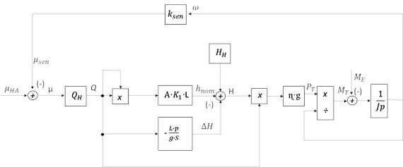
Fig. 2Block diagram of a mathematical model of a reciprocating hydraulic turbine taking into account the kinetic energy of water in the water supply
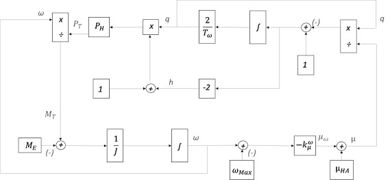
This mathematical model serves as a fundamental tool for validating the calculated parameters and for refining or tuning the system parameters required for the implementation of an effective control algorithm. According to the formulated equations, the configuration of the mixed-flow hydraulic turbine model was established. Utilizing the previously defined mathematical relationships, a comprehensive structural block diagram of the mixed-flow turbine was constructed to represent the dynamic and control interactions within the system.
The structural diagram was developed by incorporating the key operational parameters of the hydraulic turbine, including the turbine torque, hydraulic power output, angular velocity coefficient, and the effective water head level. These parameters collectively define the dynamic characteristics of the turbine and ensure that the model accurately reflects the real-time behavior of the hydro-mechanical system under varying operating conditions.
5. Results
Using the above mathematical expressions, a mathematical model was developed, and based on this model, the following results were obtained. The results are presented in Table 1:
Table 1Water consumption and results of the turbine rotation frequency to achieve the nominal rotation frequency of a micro-hydropower plant using a hydro turbine
Q | 1.34 | 2.68 | 4.03 | 5.36 | 6.7 | 8.04 | 9.4 |
n | 78 | 156 | 234 | 312 | 390 | 468 | 546 |
6. Conclusions
Based on the analysis of the physical processes occurring within the hydraulic system of the hydro unit employed in micro-hydropower plants, the mathematical model of the mixed-flow hydraulic turbine has been further refined. The study identified the feasibility of evaluating the rotational speed in a conventional hydro unit operating with an asynchronous generator, where the rotational speed is determined by the constant network frequency. As a result, new analytical outcomes were obtained.
The developed mathematical description of the mixed-flow hydraulic turbine was validated by comparing the parameters derived from the model with those obtained from computational analysis and parameter refinement for the desired control algorithm. This verification confirmed the accuracy of the model and established a foundation for developing an advanced mathematical model of the asynchronous generator integrated into micro-hydropower plants.
References
-
N. Pirmatov, S. Mahamadjonov, M. Matqosimov, and H. Haydarov, “Characteristics of the static and dynamic operating modes of the asynchronous generator in renewable energy sources and the production of electric energy control through a frequency converter,” (in Tajikistan), in E3S Web of Conferences, Vol. 480, p. 01007, Jan. 2024, https://doi.org/10.1051/e3sconf/202448001007
-
N. Pirmatov, M. Matqosimov, S. Mahamadjonov, and E. Xolmatov, “Investigation of transients in asynchronous generators used in microhydroelectric power plants,” (in Ukraine), in E3S Web of Conferences, Vol. 508, p. 02007, Apr. 2024, https://doi.org/10.1051/e3sconf/202450802007
-
N. Pirmatov, M. Matqosimov, S. Mahamadjonov, and S. Sayitov, “Analysis of various operating modes of the microhpp asynchronous generator using the matlab simulink program,” (in Ukraine), in E3S Web of Conferences, Vol. 508, p. 02012, Apr. 2024, https://doi.org/10.1051/e3sconf/202450802012
-
B. Shodiyev et al., “Electrical energy saving analysis based on solar power collector’s thermal system,” (in Uzbekistan), in E3S Web of Conferences, Vol. 497, p. 01004, Mar. 2024, https://doi.org/10.1051/e3sconf/202449701004
-
U. Berdiyev and M. Matqosimov, “Prospects for the use of renewable energy sources,” Bulletin news in New Science Society International Scientific Journal, Vol. 1, No. 3, pp. 215–221, 2024.
-
A.-Z. R. Djendubayev, “Autonomous Asynchronous Generator with Two Stator Windings and Capacitor Self-Excitation,” (in Russian), Moscow, 2005.
-
Y. A. Ilchenko, “An asynchronous generator with enhanced performance characteristics for electrotechnological systems used in pond fish farming,” (in Russian), Krasnodar, 2012.
-
D. B. Kodirov, “The potential of operating small hydroelectric power plants in the republic,” (in Uzbekistan), Problems of Informatics and Energy, No. 6, pp. 54–59, 2015.
-
I. P. Kopilov, Electric Machines. (in Russian), Moscow: Visshaya shkola, 2006.
-
U. Berdiyev, F. Xasanov, and L. Jiyanqulov, “Auxiliary electric drive with asynchronous engines based on composite materials,” (in Uzbekistan), in AIP Conference Proceedings, Vol. 3152, No. 1, p. 040014, 2024.
About this article

The authors have not disclosed any funding.
The datasets generated during and/or analyzed during the current study are available from the corresponding author on reasonable request.
The authors declare that they have no conflict of interest.
