Abstract
The development of non-destructive testing methods for aircrafts, in particular vibration diagnostics, nowadays makes it possible to make a transition to predictive maintenance. To ensure such maintenance, the hidden faults of structures at an early stage of development to be diagnosed. Vibration diagnostic techniques are already used for helicopters and considered as promising but most helicopters do not have on-board systems. An approach that does not require specialized onboard equipment is needed. To be effective such an approach should provide diagnostics in field conditions using a one-time inspection. Application of the system’s prototype, which meet these requirements is suggested and discussed in this paper. Workability of the methods used has been demonstrated in testing of healthy and aged sets of main rotor blades. The method of blades state assessing using modal diagnostic parameters are briefly described and comparison of diagnostic parameters between healthy and aged blades are discussed.
Highlights
- Vibration diagnostic technique for inspecting the helicopter blades condition in field
- The portable set of equipment transportable to any destination for blades inspection
- Trial application of the technique and equipment for separating the aged and healthy helicopter blades
1. Introduction
Different non-destructive techniques are used for inspecting the helicopter blades, depending on whether the methods are used as a part of on-board system or a ground-based system. On-board health and usage monitoring systems may consider many methods to avoid the possibility of rotor failure, including real-time vibration and ultrasound signal analysis, acoustic emission, temperature deviation and thermography as well as other operational parameters [1]. An approach to structural health monitoring of helicopter rotors based on strain measurement of blades was offered in [2]. The method uses analysis of the discrepancies between the strains on damaged and undamaged blades applying a multibody dynamic solver for comprehensive aero-elastic analysis of rotorcraft in both steady-flight and soft maneuvers. An example of such approach experimental application to wind turbine rotor blades is given in [3]. Most helicopters do not yet have an onboard system capable of monitoring the condition of the blades, so the main emphasis is on inspecting the blades on the ground. In [4] authors in addition to on-board methods consider the non-destructive techniques for on-ground inspection of blades including modal methods, acoustic emission, ultrasonic and eddy current methods, and computed tomography. Other modern techniques for example, digital shearography and infrared thermography techniques were studied for quantification of faults seeded into helicopter rotor blade [5]. As more promising the modal analysis techniques may be considered, as they allow assessing both changes in material characteristics due to either wear or aging, and local defects caused by foreign objects. In recent work [6] authors presented the Modal Passport (MP) approach to on-ground inspection of helicopter blades. The modal properties of a blade estimated using vibration signals and Operational Modal Analysis (OMA) techniques are the core data for diagnosing. Condition of the blade is assessed by comparing the modal properties determined in the test with the reference properties. For diagnosing the blade by single inspection, as the reference the modal properties of serviceable blades are considered. For blade excitation the impulse actuator is used and vibrations along 48 Degree of Freedoms (DOFs) are measured using the portable system.
The parameters of modal distance (MD) estimated in modal space are used in [7] as the measures of the blade structural change. To determine the blade’s modal properties in field conditions, the MP considers using the set of testing and computational techniques [6]. The prototype system has been created for assessing the condition of both the helicopter's rotating units and blades in field conditions. The portable equipment set for testing blades can be transported to the helicopter's location as a typical luggage. The in-field validation of MP techniques were conducted, in which the tested blade was suspended to the helicopter tail beam. The trial application of the technique presented in [6] involved 5 serviceable and two unserviceable (exceeded service life) blades. Parameters of MD were estimated for each blade and the difference of diagnostic parameters between the “healthy” and unserviceable blades was found. Although the results of above mentioned tests were positive, some issues need to be addressed before MP can be used in practice for the diagnosis of blades. More samples of blades are required for confident recognizing the blade’s condition using the MD parameter. It must also be taken into account the helicopter blades are delivered and installed on a helicopter as a rotor set. Practical application of MP also needs alternative test method, in case if helicopter could not be used as the test basis.
The objective of the study is to verify applicability of MP techniques for detecting defective rotor blades using data of single in-field inspection. Aiming to address above mentioned issues, three blade sets, including two serviceable and one faulty were included in the test sample. The ability of MP techniques to detect faulty blades should be demonstrated by minimal MD between healthy blades compared to significantly larger MD for faulty blades. Another objective is to verify the possibility of testing blades without helicopter, using the special equipment set. Methodology of the study and equipment used is described in Section 2, while the research results are discussed in Section 3, and conclusions in Section 4.
2. Modal testing of the blades
2.1. Test and measurement set-up
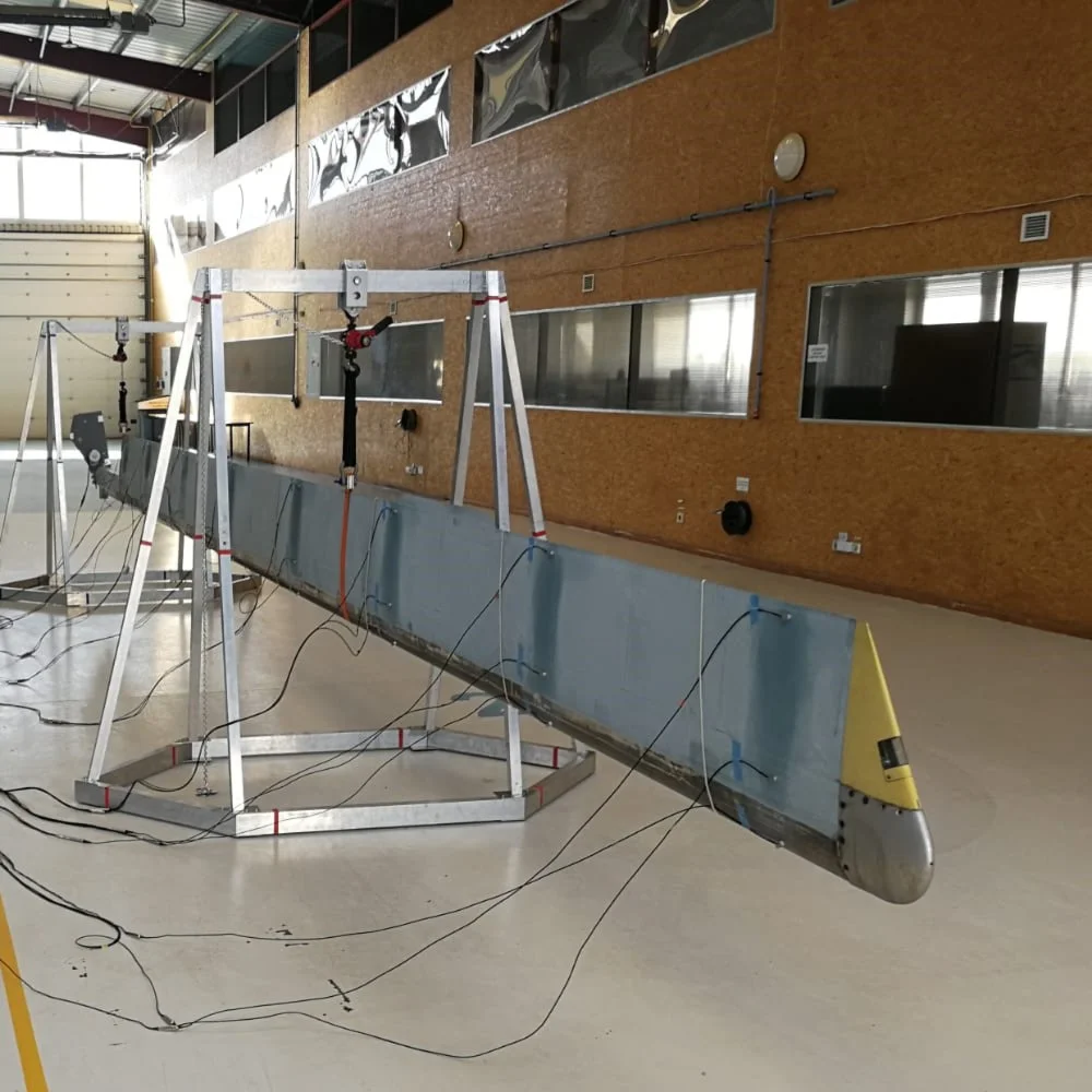
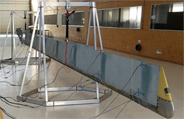
The blade type of medium-heavy class helicopter similar to the blades used in [6] was used for testing. One set of brand new blades and second set of repaired ones had airworthiness status. Five “aged” blades of the third set had ran out service life and some of them had damages. For testing, the blade is suspended on two detachable tetrahedron-shaped supports for more rigidity (Fig. 1(a)). The easy-to-assemble supports allow fitting the units in one bag and transporting as a luggage.
Fig. 1Test set-up and portable test rig. The photo was made by one of authors – Aleksejs Safonovs 17.09.2025 at Kaunas Lithuania
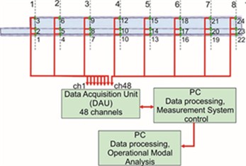
The actuator, fixed on the blade’s root, like in [6], excites the natural oscillations of the blade repeating pulse strikes with a period twenty time less than period of lowest mode 5,2 Hz of the blade known from [6]. As the OMA techniques were used for modal properties identification the process of vibration measurement and recording was permanent. Testing of each blade included three repeated tests that allows reducing uncertainty of the modal parameters by enhancing the initial estimates. Three-axial accelerometers are installed at 24 points on the blade surface (Fig. 1(b)) and distributed in 8 sections evenly spaced from root to tip. In each section the transducers are glued next to leading and tail edges and at the maximum height of blade profile. Data acquisition unit (DAU) provides conditioning and measures 48 signals generated by each accelerometer orthogonally and tangentially to the blade surface. Frequency range of interest was earlier studied in [6] and limited to 1…200 Hz. The data obtained in tests is accumulated in laptop controlling the measurement and file composing processes. Minimal measurement uncertainty in terms of amplitudes is 1.5 % for the range 10…1000 m/s2 and frequency up to 10 kHz and grows with decreasing amplitude and growing frequency. Uncertainty of frequency is an order less.
2.2. Modal data estimation
Vibration signals measured in 48 Degree of Freedoms (DOFs) are the source of information about the modal state of the tested blade. There are two stages of diagnostic procedures: vibration data processing and modal parameters calculation. The commercial software ARTeMIS processes vibration signals using most usable OMA algorithms considering each signal as a response in DOF corresponding to a modal model of the blade. ARTeMIS estimates modal parameters applying the most usable OMA techniques, including Enhanced Frequency Domain Decomposition, Canonical Variate Analysis and Unweighted Principal Component analysis. Rough estimates of modal parameters are the result of vibration signals processing. To reduce the uncertainty of modal estimates and to increase repeatability, the MP applies algorithms of modal enhancement discussed in details in [7]. For instance, increasing number of enhanced tests from 3 to 10 uncertainty reduces on 25-27 %. The parameters of sustainable modes including frequency (), damping () and eigenvector () as shape description are the result of modal enhancement that MP algorithms use for calculation of blade diagnostic parameters.
3. Diagnostic parameters
The MP considers the state of blade as point B in a multidimensional modal space. The coordinates of this point B and length of the vector from origin to B may be used as the diagnostic parameters. Coordinates of the point correspond to frequency and damping axes, as well as to dimensions of modal shape matrix associated with DOF number. The origin in this space corresponds to the reference point against which the blade condition is compared. As the reference the modal parameters of one or a set of healthy blades could be used. All measures in this space, re calculated as relative difference, like in [7] between the calculated modal parameter and the etalon (0), therefore called MD. For scalar frequency and damping of particular mode the simplest MD is calculated as Eqs. (1) and (2):
Shape MD measures the geometric sum of the modal shape difference from etalon in 48-dimensional space normalized to DOF number Eqs. (3):
Typical modal tests of the blade provide identifying the sustainable modes, and to take all them into account the integral parameters of modal distance (MDI) are calculated for frequency, damping and shape:
Integral parameters of MD are used to estimate change of different aspects of blade’s mechanical properties and structural integrity. For example, MDI of frequency and damping as global parameters of blade are more sensitive to material properties modification due to aging or wearing. Opposite, the shape MDI can be more sensitive to change of structural integrity, for example due to a damage caused by foreign object. Any such structural damage modifies mass-rigidity ratio in a blade which leads to a change in the modal shape.
The harmonized MD parameter (MDIh) allows taking into account the modal distances of frequency, damping and shape. This parameter corresponds to length of vector describing the blade’s state in the modal space. Harmonization is required as the scales of modal parameters differ. For tested blades, the scale of frequency and shape MD parameters are about hundred times less. As a reference for harmonization the upper limit of MDI parameter’s distribution area is used. The latter is estimated as the sum of average and uncertainty for sample values of particular MDI parameter. For calculating above statistics the MDI of blade group of one rotor set are used as a sample. Uncertainty scores of MDI parameters are known from research study in [7]. Using assumption of a Gaussian distribution within the sample the uncertainty with a confidence level 99.7 % is computed as the triple standard deviation of the MDI estimates Eqs. (5):
Then harmonized MDI parameter is calculated as Eq. (6):
Resuming the harmonized MD of tested blade is calculated:
The harmonized MDI allows global characteristic of the blade’s state in comparison to etalon using the test data of a single inspection. In case if the parameter level could be considered as abnormal, further diagnosing may be undertaken using more specified MDI parameters considered above.
4. Discussions
Three sets of 5 blades each, were tested using measurement set-up described in Section 2.1. Two sets (1H and 2H) involved the serviceable blades intended for installation on the helicopter for flight operation. The third set consisted of blades that had completely exhausted their service life and were unsuitable for flights. In accordance with the testing and measurement procedures described in Section 2.1, all 15 blades were tested. The data obtained from the tests were used to calculate the modal parameters of each blade in accordance with Section 2.2. The number of sustainable modes identified for each blade varies between blades: unserviceable blade A5 has 5, while healthy blade 1H1 has 11 sustainable modes.
As the blade 1H1 from first serviceable set has the largest number of sustainable modes, modal parameters were taken as the etalon of healthy state. Using Eqs. (1-3) given in Section 3, the MD parameters were calculated for each mode of the remaining 14 blades (1H2, 1H3, 1H4, 1H5, 2H1, 2H2, 2H3, 2H4, 2H5, A1, A2, A3, A4, A5). Then, applying Eq. (4) the integral parameters (MDI) of frequency, damping and shape were calculated for 14 blades. The average values and standard deviations of the integral MD for each set of blades are given in Table 1. The values given in the table demonstrate the MD variation between the groups of blades. For example, values 0.24 % and 0.29 % of integral frequency parameter MDIf mean that the modal frequencies of the serviceable blades differ from the etalon by about a quarter of a percent, with a standard deviation of about 0,09-0,1 %. For aged blades, the average MDIf (0.85 %) increases to triple, and the spread between the blades is twice as large.
Table 1Basic size and style requirements
State | Statistic parameter | MDIs | MDId | MDIf | MDIh |
Healthy 1 | Average | 0.45 % | 13 % | 0.24 % | 0.99 |
SD | 0.04 % | 4 % | 0.10 % | 0.19 | |
Healthy 2 | Average | 0.48 % | 13 % | 0.29 % | 1.05 |
SD | 0.07 % | 5 % | 0.09 % | 0.20 | |
Aged | Average | 0.52 % | 18 % | 0.85 % | 1.92 |
SD | 0.03 % | 5 % | 0.24 % | 0.43 |
A much smaller difference between the blades occurs for the modal shape parameter (MDIs), which also has a smaller spread between the blades (0.03 % – 0.07 %). The average values and spread of the damping parameter turned out to be almost the same for both sets of serviceable blades, and by 30 % higher for the aged blades. The values given in the table demonstrate the MD variation between the groups of blades. For example, values 0.24 % and 0.29 % of integral frequency parameter MDIf mean that the modal frequencies of the serviceable blades differ from the etalon by about a quarter of a percent, with a standard deviation of about 0,09-0,1 %. For aged blades, the average MDIf (0.85 %) increases to triple, and the spread between the blades is twice as large. A much smaller difference between the blades occurs for the modal shape parameter (MDIs), which also has a smaller spread between the blades (0.03 %-0.07 %). The average values and spread of the damping parameter turned out to be almost the same for both sets of serviceable blades, and by 30 % higher for the aged blades.
Above changes of modal properties correspond to physics. The modal frequencies, which are related to the elastic properties of the blade materials, appear to be the most sensitive to “aging” of the blade. Aging had a lesser effect on the damping of natural modes. The mode shape is related to the geometric distribution of masses over the volume of the blade, and since the integrity of the structure of the aged blades is not damaged, the mode shapes did not change.
Histogram in Fig. 2 illustrates harmonized MD parameters for blades of two healthy (green and blue) blade sets and the aged one (brown).
Fig. 2Harmonized modal distance of 14 blades
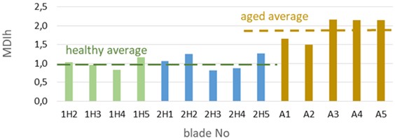
The MDIh of new blades varied around 0.99 (green dotted line) with a spread about 0.19, while the parameter of repaired blades increased a bit (mean 1,05, spread 0,2). Parameters of aged blades were almost twice higher 1.92 (brown dotted line) with twice increased spread (0.43). Therefore, MD parameters allow diagnosing the “aged” blades due to change of modal properties. Environment, especially temperature, affects modal parameters and may limit the use of MP at unchanged ambient conditions only. To avoid this limitation, and to compare parameters determined at different environments, the experimentally determined influence functions to be used, bringing parameters to the reference conditions.
5. Conclusions
Three rotor sets with 5 helicopter blades in each were subjected to modal tests applying the OMA and Modal passport techniques. Two sets included only “healthy” blades, while “aged” third one had ran out service life. The portable equipment set was used allowing modal tests of helicopter blades in field conditions without a helicopter. Modal parameters of all blades were estimated using standard OMA methods, and the diagnostic parameters of modal distance were calculated for each of 14 blades. Application of the portable equipment for blades testing confirmed its workability in field. Comparison of modal diagnostic parameters between blades allows identifying the aged blades applying diagnostic parameters of harmonized integral modal distance.
Next stage of the test program includes repeated tests for the same type and for lighter helicopters, like Cabri G2 and Eurocopter EC 135 to expand datasets.
References
-
O. Roshchupkin and I. Pavlenko, “Modern methods for diagnosing faults in rotor systems: a comprehensive review and prospects for AI-based expert systems,” Applied Sciences, Vol. 15, No. 11, p. 5998, May 2025, https://doi.org/10.3390/app15115998
-
J. Serafini, G. Bernardini, R. Porcelli, and P. Masarati, “In-flight health monitoring of helicopter blades via differential analysis,” Aerospace Science and Technology, Vol. 88, pp. 436–443, May 2019, https://doi.org/10.1016/j.ast.2019.03.039
-
D. Tcherniak and G. Larsen, “Application of OMA to an operating wind turbine: Now including vibration data from the blades.,” in 5th International Operational Modal Analysis Conference, IOMAC 2013, 2013.
-
P. M. Pawar and R. Ganguli, “Helicopter rotor health monitoring – a review,” Proceedings of the Institution of Mechanical Engineers, Part G: Journal of Aerospace Engineering, Vol. 221, No. 5, pp. 631–647, May 2007, https://doi.org/10.1243/09544100jaero245
-
D. Findeis, J. Gryzagoridis, and V. Musonda, “NDT detection and quantification of induced defects on composite helicopter rotor blade and UAV wing sections,” in 9th International Symposium on Laser Metrology, Vol. 7155, p. 71551N, Sep. 2008, https://doi.org/10.1117/12.814560
-
A. Mironov, P. Doronkin, A. Safonovs, and V. Kuzmickis, “Field testing of mechanical properties of composite blades using their modal properties,” Mechanics of Composite Materials, Vol. 61, No. 3, pp. 633–648, Jun. 2025, https://doi.org/10.1007/s11029-025-10297-4
-
A. Mironov, A. Safonovs, D. Mironovs, P. Doronkin, and V. Kuzmickis, “Health monitoring of serial structures applying piezoelectric film sensors and modal passport,” Sensors, Vol. 23, No. 3, p. 1114, Jan. 2023, https://doi.org/10.3390/s23031114
About this article

This research was funded by Central Finance and Contracting Agency Republic of Latvia, Project number 5.1.1.2.i.0/2/24/A/CFLA/002.
The datasets generated during and/or analyzed during the current study are available from the corresponding author on reasonable request.
The authors declare that they have no conflict of interest.
