Abstract
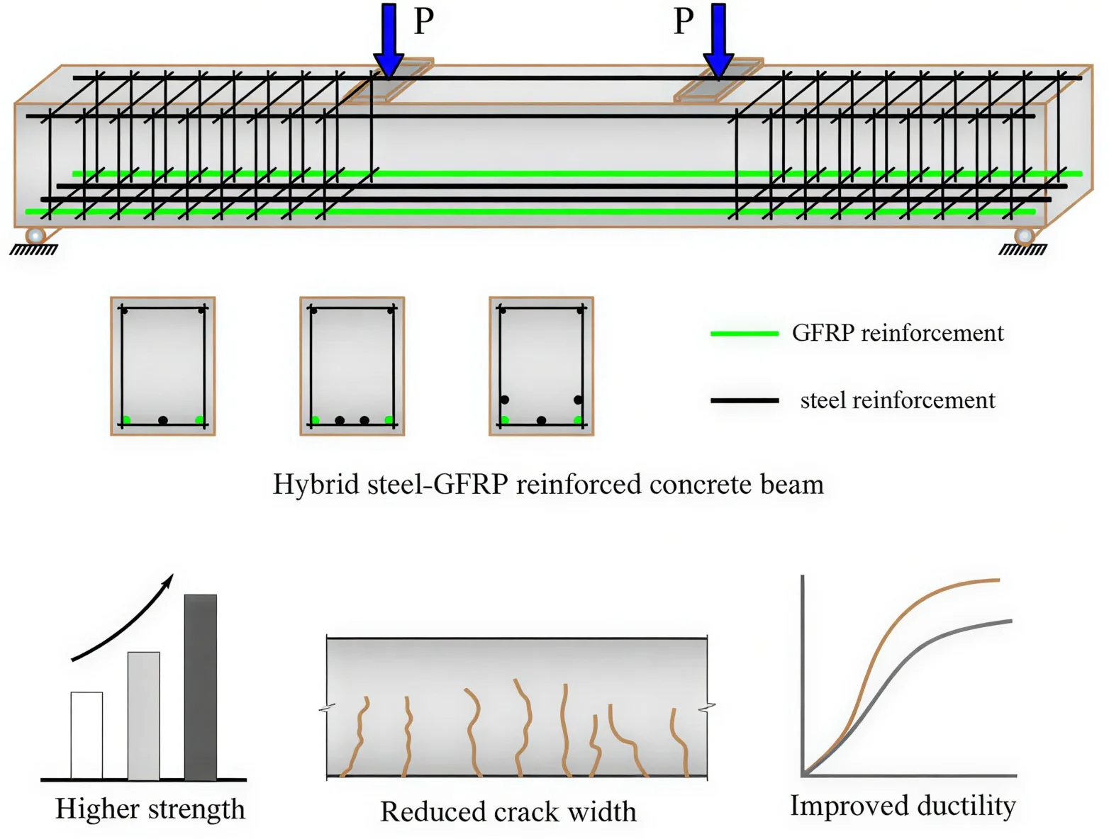
The use of steel reinforcement in reinforced concrete elements negatively affects the long-term durability and reliability of structures due to its susceptibility to corrosion. At the same time, the relatively low elastic modulus of fiber reinforced polymer (FRP) reinforcement leads to increased deformation and deflection when applied independently in beams. Therefore, hybrid steel-FRP reinforcement provides an opportunity to compensate for the shortcomings of each material. However, computation methods for hybrid reinforced concrete beams are not presented in the current design codes. This article highlights the theoretical analysis of hybrid-reinforced beams and presents the obtained results, which are validated by experimental data obtained from tests on 27 beam specimens under four-point bending. The comparison between theoretical and experimental findings confirmed the accuracy of the proposed analytical model and demonstrated the enhanced strength and ductility of hybrid steel-GFRP reinforced concrete beams.
Highlights
- Hybrid steel-FRP reinforcing increases the ductility and durability of structures, which allows it to be applied in concrete design in sustainability.
- Hybrid steel-FRP reinforced concrete beams were analytically and experimentally studied under flexural loading.
- The presented analytical model is accurate in predicting the responses of load-deflection and cracking behavior of the hybrid beams.
- GFRP reinforcement delays steel yielding in the hybrid reinforced concrete beams.
- Hybrid reinforced concrete beams demonstrate better serviceability performance and stiffness, which is experimentally proven.
1. Introduction
Concrete, which is formed from the slow hardening of a mixture of binder, filler, and water, is characterized by high compressive strength and relatively low tensile strength [1]-[2]. Therefore, steel reinforcements are used in the tensile zones of reinforced concrete elements to resist tensile stresses [3]. Using a ductile material in concrete alongside its strength is of critical importance, since strength ensures the direct transfer of loads in the structure, while ductility prevents brittle failure [4]-[5].
For many years, steel reinforcements have served as the simplest and most effective solution for providing both strength and ductility in reinforced concrete structures, becoming a conventional material. If protected from external influences, particularly corrosion, steel reinforcement can function for long periods without physical deterioration [6]-[8]. However, in structures exposed to open conditions such as bridges treated with de-icing salts in winter or constructions over water bodies preventing corrosion is nearly impossible. When combined with humidity, temperature and chlorides accelerate corrosion of steel reinforcement, leading to structural deterioration and significantly affecting the durability of the structure [9]-[10].
To address the problem of steel corrosion and to extend the service life of reinforced concrete structures, a number of methods have been applied, including: metal coatings, protective layers, anti-corrosion alloys and alloying agents, anodic and cathodic protection, corrosion-resistant composites, and stainless metals. However, the effectiveness of these materials and compounds is limited, and they are often economically expensive. Therefore, in recent years, reinforcing reinforced concrete structures with FRP has been considered one of the effective solutions worldwide [11]-[12].
The durability of reinforced concrete structures depends on numerous factors, the majority of which are associated with the corrosion of steel reinforcement. This is considered one of the most widespread issues that hinders the long-term service life of structures, buildings, and facilities. Therefore, the durability of steel reinforcement in reinforced concrete structures has been the subject of extensive research, with many recent studies serving as clear examples of this trend [13]-[14].
Recent experimental investigations on structural integrity have demonstrated that corrosion resistance has a significant effect on the durability of structural elements. In particular, over the last two decades, growing attention has been directed toward the use of glass fiber-reinforced polymer (GFRP) bars as an alternative to steel reinforcement in concrete structures. Because they naturally resist corrosion, GFRP bars are being used more often as a good replacement for steel in structures that are in harsh environments [15]-[16].
GFRP bars possess high tensile strength, reaching up to 1100 MPa, which is several times greater than that of ordinary A400 steel reinforcement (400 MPa). However, unlike steel, GFRP bars do not exhibit a yield plateau. Consequently, concrete structures reinforced with GFRP are not considered as reliable under overloads, crack formation, or excessive deformations, since the lack of plasticity may lead to brittle failure. In other words, the relatively low modulus of elasticity of GFRP results in large elastic deformations, but this does not prevent brittle failure. For this reason, when GFRP reinforcement is applied in concrete beams, higher reinforcement ratios and larger safety factors must be adopted [17].
2. Methods
2.1. Parameters of beam, concrete and reinforcements
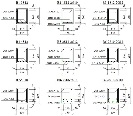
For the experiment, a total of 27 beams in 9 series were prepared, each with a length of 150 cm and an effective length of 140 cm. The cross-sectional dimensions were taken as 15×20 cm. The applied load was placed at a distance of /3 along the beam. The distance from the edge of the beam to the support was set at 5 cm. All beams were tested under four-point bending [2].
Considering that the beams were to be tested under normal section conditions, no transverse reinforcement was provided in the midspan region. At the regions near the supports, the spacing of transverse bars was set to 5 cm. The reinforcement cage had a length of 145 cm and a height of 18 cm. All beams were reinforced with 2Ø8 A400 bars in the compression zone. Stirrups were made of Ø6 A240 bars [2].
The cross-sectional dimensions of the beams, the positioning of the reinforcement cage within the beam, and the placement of steel and GFRP bars in the tensile zone are illustrated in Fig. 1.
2.2. Calculation of hybrid steel-GFRP beams at ultimate limit states
In hybrid steel-GFRP reinforced concrete beams, the use of three different materials leads to failure occurring in various combinations. In these cases, failure manifests similarly to the previously described beams, including crushing of concrete in the compression zone, yielding of steel reinforcement, and rupture of GFRP bars [2].
As noted above, the theoretical study and development of calculation methods for failure of reinforced concrete beams with hybrid steel-GFRP reinforcement differ from those for beams reinforced solely with steel or FRP reinforcement. Based on the research findings of Nguyen P.D. [1], and others, six types of failure modes can be observed in hybrid steel-FRP reinforced concrete beams.
In the failure modes 1, 2 and 3, the combined area of steel and FRP reinforcement is relatively small compared to the concrete cross-sectional area. The 5th and 6th modes correspond to over-reinforced sections, while the failure mode 4 reflects practical reinforcement ratios that are closer to real structural applications. Among these, modes 3 and 5 are referred to as neutral states, characterized by simultaneous failure of two or three materials - namely, crushing of the concrete in the compression zone, yielding of steel reinforcement in the tensile zone, and rupture of the composite polymer reinforcement [2].
Fig. 1Cross-sections of the test beams and arrangement of the reinforcement cages
Failure mode 4 is considered in this study because it represents the most critical and practical scenario for hybrid steel–FRP reinforced concrete beams. In failure mode 4, the first concrete crushes then the steel reinforcement reaches its yield point, leading to significant deflection while the FRP reinforcement does not rupture. This failure mode of the beam governs the design under typical loading conditions and provides a ductile failure. However, failure mode 1, 2 and 3 are tension-controlled with insufficient reinforcement, or failure mode 5 and 6 are over-reinforced or compression-controlled which fail in a brittle behavior. Therefore, failure mode 4 corresponds to a practical approach for structural design.
When calculating hybrid steel-GFRP reinforced beams according to ultimate limit states, the analysis is based on the third stage of the stress-strain state of bending elements. In this stage, after cracks have formed in the tensile zone, it is assumed that tensile stresses are carried only by the longitudinal reinforcement, while the contribution of the tensile concrete is neglected [7].
This article presents the calculation method for failure mode 4 of hybrid steel-GFRP reinforced concrete beams, and the results obtained from these calculations are analyzed.
Failure mode 4. This failure mode is analogous to that observed in moderately reinforced steel-reinforced concrete beams. Initially, the stress in the steel reinforcement reaches its yield strength, after which the stresses are transferred to the GFRP bars, leading to an increase in their deformations; however, rupture does not occur. At the same time, concrete in compression zone crushes. As a result, the strength capacity of the GFRP reinforcement is not fully utilized, leaving an unused reserve (Fig. 2).
From Fig. 2, ultimate moment of the beam can be determined by calculating the moment relative to the axis passing through the centroid of the GFRP reinforcement in the tensile zone:
where: – compressive prism strength of concrete; – width of the beam; – height of the compressive zone; – effective depth of GFRP reinforcement; – effective depth of steel reinforcement; – yield strength of steel reinforcement; – cross-sectional area of steel reinforcement in the tensile zone.
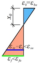
Fig. 2Analytical model for failure mode 4 of hybrid steel-GFRP reinforced concrete beams: a) cross-section of the beam; b) strain distribution; c) equivalent stress diagram
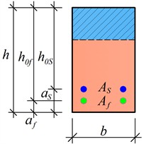
a)
b)
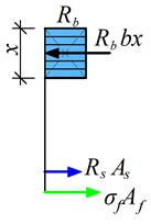
c)
By projecting all the forces acting in the cross-section onto the -axis, Eq. (2) can be derived:
where: – tensile strength of GFRP reinforcement as used in Eq. (3); – cross-sectional area of GFRP reinforcement in the tensile zone:
The relative strain in the GFRP reinforcement is evaluated from the strain distribution depicted in Fig. 3:
By substituting Eqs. (3) and (4) into Eq. (2), Eq. (6) is obtained:
where: 0.85 is the coefficient used to convert the parabolic stress distribution in the concrete compression zone into an equivalent rectangular stress block.
The height of the compression zone can be determined as follows:
3. Results and discussion
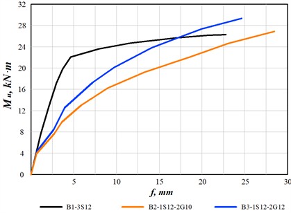
In Fig. 3, the moment-deflection diagram for the Series 1 beams (B1-3S12, B2-1S12-2G10, and B3-1S12-2G12) under loading is shown. The vertical axis of the diagram represents the ultimate moment (kN·m), while the horizontal axis indicates the maximum deflection f (mm) at the middle of the beam. In other words, this diagram can also be referred to as the stiffness and flexibility of the beam.
A normally reinforced concrete beam with steel reinforcement had a linear behavior until reaching the ultimate moment 23.21 kN·m and reached the maximum stiffness. This situation is explained by the fact that normal stress in the steel reinforcement reached its yield limit. The B2-1S12-2G10 beam had the smallest stiffness because the amount of reinforcement was less compared to the other two beams. In this beam, since the reinforcements were applied in a combined manner, the ductility of the steel reinforcement was not clearly observed.
The ultimate moment value was observed in B3-1S12-2G12 with 28.74 kN·m, while the smallest was in the steel-reinforced concrete beam B1-3S12 with 26.19 kN·m. In B2-1S12-2G10, was 26.92 kN·m. Maximum deflection was observed in B2-1S12-2G10 with 28.43 mm, and minimum in the reinforced concrete beam B1-3S12 with 22.87 mm. In B3-1S12-2G12, it was 24.75 mm.
With the same reinforcement ratio, the strength of hybrid beams was 9.7 % higher compared to conventional reinforced concrete beams, and the deflection at the failure stage was 8.2 % greater.
Fig. 3Moment-deflection diagram for Series 1 beams
In Fig. 4, the development of deflection under loading for the Series 2 beams is shown. The stiffness of the steel-reinforced beam B4-4S12 increased until the steel reinforcement reached the yield plateau; as the moment value ranged from 28.74 kN·m to 30.68 kN·m, the beam’s stiffness sharply decreased, and the deflection value also correspondingly reached from 5.16 mm to 17.28 mm, marking the ultimate load-carrying capacity of the beam.
Similar to the steel reinforced concrete beam, the B5-2S12-2G12 beam with a reinforcement ratio of 1.68 % developed deflections in linear under loading. The yield plateau of the steel reinforcements was also hardly noticeable. However, the ultimate load-carrying capacity at failure was higher compared to conventional concrete beam (31.73 kN·m). At the same time, it can be seen from the diagram that the deflection also increased (23.03 mm). A sudden drop in stiffness was not observed in the hybrid steel-GFRP reinforced concrete beams.
The specimen B5-2S12-2G10, which had a smaller reinforcement ratio (1.42 %) compared to the other two beams, reached a smaller ultimate moment value (28.68 kN·m) and with the largest deflection (27.06 mm). In the Series 2 beams, when the reinforcement ratio was equal, the strength of the hybrid beams was 3.4 % higher than that of the steel-reinforced concrete beams, and the deflection was 33.3 % greater.
All beams in Series 3 had the same reinforcement ratio, 1.59 %. Since the modulus of elasticity of steel reinforcement is higher than that of GFRP, the deflection of the steel-reinforced concrete beam (B7-5S10) in the elastic region, up to the steel’s yield point, was greater than that of the hybrid steel-GFRP reinforced beams, as shown in Fig. 5. However, after reaching the yield limit, the deflection of the conventional steel reinforced beam decreased sharply. The deflection at the yield point was 5.24 mm, increasing to 19.71 mm at the ultimate stage. The corresponding moment values were 22.78 kN·m and 26.58 kN·m, respectively.
Fig. 4Moment-deflection diagram for Series 2 beams
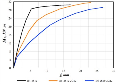
Fig. 5Moment-deflection diagram for Series 3 beams
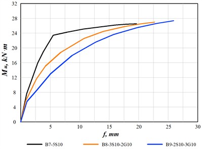
In hybrid steel-GFRP reinforced beams, increasing the amount of GFRP reinforcement led to higher deflections while simultaneously achieving ultimate moment. The ultimate moment values were 27.15 kN·m for B8-3S10-2G10 and 27.37 kN·m for B9-2S10-3G10, with corresponding deflections of 22.63 mm and 26.08 mm. Compared with conventional steel-reinforced beams, the hybrid steel-GFRP beams in Series 3 exhibited a 2.1-2.9 % increase in load-carrying capacity and a 14.8-32.3 % increase in deflection.
According to the results, the combination of steel and GFRP bars greatly impacts the flexural behavior and deformation characteristics of the beams. In Series 1, hybrid steel-GFRP beams had greater moment capacity and deflection due to the synergistic action of both reinforcements compared with conventional steel-reinforced concrete beams. In the initial phase of the loading, the steel rebar in hybrid beams reached their yield point, then the GFRP bars continued to carry tensile forces. Thus, failure was delayed, and the moment capacity of the beams increased slightly. The use of steel and GFRP bars in hybrid beams explains the smoother load-deflection diagram and increased energy absorption capacity identified in the beams.
For Series 2 beams, the gradual stiffness reduction illustrates that the existence of GFRP bars controlled the deformation and deflections of the beams. The hybrid steel-GFRP beams can accept loads and maintain load-bearing capacity even after steel bars reached the yield point. This indicates that inclusion of GFRP bars prevents the sudden stiffness reduction of the beams and redistribution of tensile stresses between the steel and GRRP bars as well as improving residual strength and deformative characteristics. Additionally, the greater deflection is the resultant ductility which is important feature for structural elements subjected to seismic loads.
In Series 3, the results showed that the proportion of GFRP in the tensile zone played a significant role in controlling governing both stiffness and deflection. As the reinforcement ratio of GFRP increased, the beam exhibited larger deflections, but the stiffness in the elastic range decreased slightly due to the GFRP elastic modulus being slightly smaller compared to steel. However, this is beneficial in terms of a structural safety, providing warning signs before failure, while maintaining a sufficient strength reserves. For hybrid steel-GFRP beams, there is a slight increase in moment capacity (2-3 %), the GFRP contribution being more effective at a later stage than the yield strength of the steel, and the reduction in stiffness is compensated by the GFRP.
4. Conclusions
In this study, load carrying capacity and deflection of hybrid steel-GFRP reinforced concrete beams were investigated. As a result of the theoretical analysis, several important results were obtained:
1) Using steel and GFRP reinforcements in a hybrid way allows effective use of the advantages of both materials. Steel provides ductility and prevents brittle failure, while GFRP increases corrosion resistance and contributes to the overall strength of the beams.
2) Hybrid steel-GFRP reinforced concrete beams demonstrated ductility compared to conventional steel reinforced beams. When the amount of GFRP in the tensile zone increased, deflection under ultimate load increased, while the safety of the structure was maintained.
3) In hybrid beams, the ultimate load was higher than in conventional steel-reinforced beams and increased by 2 % to 10 % depending on the reinforcement method and its ratio. Deflection at failure also increased significantly, showing improvement in ductility characteristics.
4) The results of the study confirmed that hybrid steel–GFRP reinforced concrete beams are an effective solution to increase the durability, ductility, and strength of reinforced concrete beams in a corrosion-resistant environment. This approach creates an effective balance between strength, ductility, and long-term durability.
Overall, concrete beams reinforced with hybrid steel-GFRP show higher efficiency compared to conventional steel reinforced beams and provide a promising alternative solution for modern structural applications requiring strength and corrosion resistance.
References
-
N. P. Duy and D. V. Hiep, “Analytical identification of failure modes and design-oriented formulations in hybrid FRP/steel reinforced concrete beams,” International Journal of Civil Engineering, Vol. 21, No. 5, pp. 727–750, Dec. 2022, https://doi.org/10.1007/s40999-022-00796-z
-
R. Mavlonov and S. Razzakov, “Numerical modeling of combined reinforcement concrete beam,” in E3S Web of Conferences, Vol. 401, p. 03007, Jul. 2023, https://doi.org/10.1051/e3sconf/202340103007
-
M. A. Safan, “Flexural behavior and design of steel-GFRP reinforced concrete beams,” ACI Materials Journal, Vol. 110, No. 6, p. 677, Nov. 2013, https://doi.org/10.14359/51686335
-
Duy Phan Nguyen and Viet Quoc Dang, “Limiting reinforcement ratios for hybrid GFRP/steel reinforced concrete beams,” International Journal of Engineering and Technology Innovation, Vol. 11, No. 1, pp. 01–11, Jan. 2021, https://doi.org/10.46604/ijeti.2021.6660
-
R. Mavlonov, S. Razzakov, and S. Numanova, “Stress-strain state of combined steel-FRP reinforced concrete beams,” in E3S Web of Conferences, Vol. 452, p. 06022, Nov. 2023, https://doi.org/10.1051/e3sconf/202345206022
-
M. A. Aiello and L. Ombres, “Structural performances of concrete beams with hybrid (Fiber-Reinforced Polymer-Steel) reinforcements,” Journal of Composites for Construction, Vol. 6, No. 2, pp. 133–140, May 2002, https://doi.org/10.1061/(asce)1090-0268(2002)6:2(133)
-
H. Y. Leung and R. V. Balendran, “Flexural behaviour of concrete beams internally reinforced with GFRP rods and steel rebars,” Structural Survey, Vol. 21, No. 4, pp. 146–157, Oct. 2003, https://doi.org/10.1108/02630800310507159
-
W. Qu, X. Zhang, and H. Huang, “Flexural behavior of concrete beams reinforced with hybrid (GFRP and steel) bars,” Journal of Composites for Construction, Vol. 13, No. 5, pp. 350–359, Oct. 2009, https://doi.org/10.1061/(asce)cc.1943-5614.0000035
-
A. Martazaev and S. Khakimov, “Dispersed reinforcement with basalt fibers and strength of fiber-reinforced concrete beams,” in The 3rd International Symposium on Civil, Environmental, and Infrastructure Engineering (ISCEIE) 2024, Vol. 3317, p. 030011, Jan. 2025, https://doi.org/10.1063/5.0266797
-
A. Martazaev, M. Orzimatova, and M. Xamdamova, “Determination of optimum quantity of silica fume for high-performance concrete,” in The 3rd International Symposium on Civil, Environmental, and Infrastructure Engineering (ISCEIE) 2024, Vol. 3317, p. 030012, Jan. 2025, https://doi.org/10.1063/5.0266799
-
R. Qin, A. Zhou, and D. Lau, “Effect of reinforcement ratio on the flexural performance of hybrid FRP reinforced concrete beams,” Composites Part B: Engineering, Vol. 108, pp. 200–209, Jan. 2017, https://doi.org/10.1016/j.compositesb.2016.09.054
-
A. Waleed, “Flexural behavior of concrete beams reinforced with hybrid FRP bars and HRB bars,” IOSR Journal of Engineering, Vol. 9, No. 6, pp. 25–33, 2019.
-
S. Razzakov and A. Martazaev, “Mechanical properties of concrete reinforced with basalt fibers,” in E3S Web of Conferences, Vol. 401, p. 05003, Jul. 2023, https://doi.org/10.1051/e3sconf/202340105003
-
W.-J. Ge et al., “Flexural behavior of ECC-concrete hybrid composite beams reinforced with FRP and steel bars,” Journal of Composites for Construction, Vol. 23, No. 1, p. 04018069, Feb. 2019, https://doi.org/10.1061/(asce)cc.1943-5614.0000910
-
X. Ruan, C. Lu, K. Xu, G. Xuan, and M. Ni, “Flexural behavior and serviceability of concrete beams hybrid-reinforced with GFRP bars and steel bars,” Composite Structures, Vol. 235, p. 111772, Mar. 2020, https://doi.org/10.1016/j.compstruct.2019.111772
-
Z. Sun, L. Fu, D.-C. Feng, A. R. Vatuloka, Y. Wei, and G. Wu, “Experimental study on the flexural behavior of concrete beams reinforced with bundled hybrid steel/FRP bars,” Engineering Structures, Vol. 197, p. 109443, Oct. 2019, https://doi.org/10.1016/j.engstruct.2019.109443
-
D. Lau and H. J. Pam, “Experimental study of hybrid FRP reinforced concrete beams,” Engineering Structures, Vol. 32, No. 12, pp. 3857–3865, Dec. 2010, https://doi.org/10.1016/j.engstruct.2010.08.028
About this article

The authors have not disclosed any funding.
The datasets generated during and/or analyzed during the current study are available from the corresponding author on reasonable request.
The authors declare that they have no conflict of interest.
