Abstract
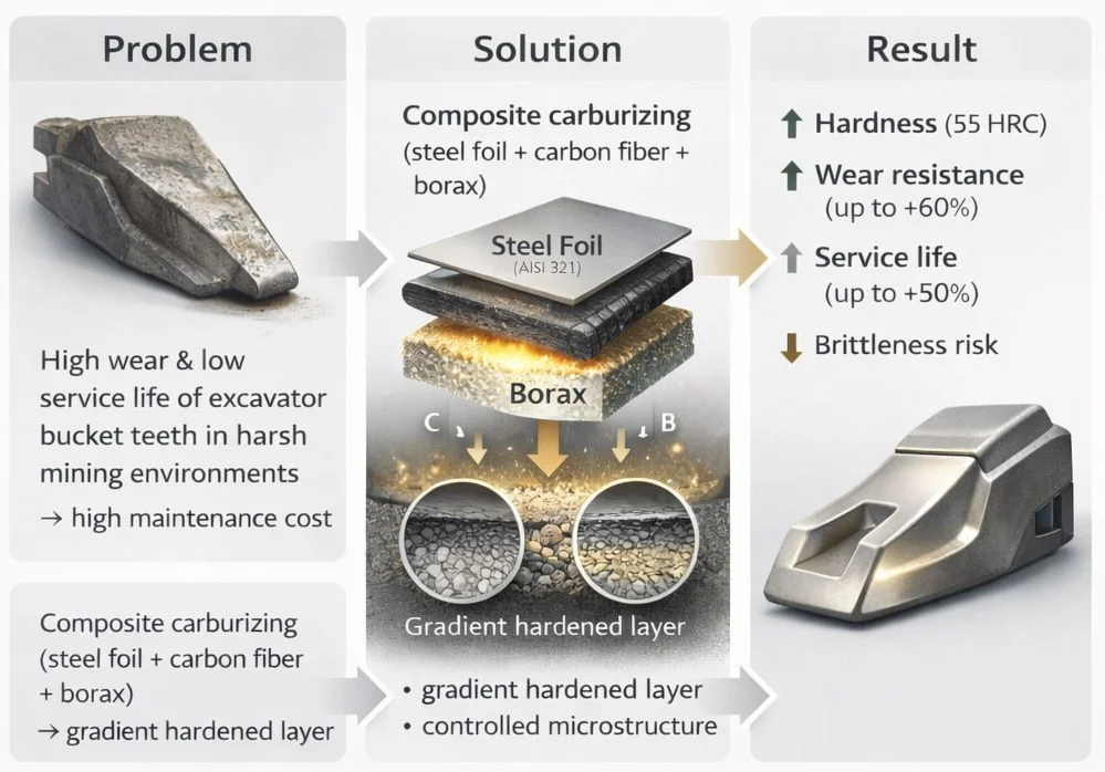
An innovative technology for the surface hardening of excavator bucket teeth by a composite carburizing method is proposed. The process is based on the application of a multilayer substrate consisting of AISI 321 stainless steel foil, carbon fiber, and borax (sodium tetraborate), followed by heat treatment in a controlled atmosphere. The experimental procedure involved the production of cast specimens in sand–clay molds and the application of various types of composite substrates. Results of microstructural examinations and hardness measurements demonstrated the high efficiency of the developed technology. It was established that the combined use of carbon fiber, metallic foil, and borax leads to the formation of a gradient hardened layer with a fine-grained structure, which ensures enhanced wear resistance and operational durability of the excavator bucket teeth.
Highlights
- A composite carburizing method using carbon fiber, steel foil, and borax forms a gradient hardened layer with refined microstructure, significantly improving surface properties without bulk heat treatment.
- Synergistic action of carbon fiber, AISI 321 foil, and borax increases surface hardness up to 55 HRC and wear resistance by up to 60% while maintaining core toughness.
- The proposed technology extends excavator bucket tooth service life by up to 50%, offering a simple, energy-efficient, and reproducible alternative to conventional carburizing methods.
1. Introduction
Modern mining equipment imposes stringent requirements on the strength and wear resistance of working components, particularly the excavator bucket teeth. Among the most effective approaches to enhancing these properties are chemical-thermal surface hardening techniques [1-3]. However, conventional methods such as carburizing and carbonitriding have several drawbacks, including limited structural control, a pronounced hardness gradient, and the requirement for complex and energy-intensive equipment [4-6]. The proposed composite carburizing method employs a multilayer reactive system composed of AISI 321 steel foil, carbon fiber, and borax (sodium tetraborate). This configuration enables the formation of a localized reaction medium that ensures uniform carbon saturation of the surface and promotes the development of a favorable phase and structural state. Within this system, the steel foil functions as a diffusion barrier and a source of alloying elements, the carbon fiber serves as an active carbon donor, and the borax acts as a flux and phase-transformation modifier [7, 8].
2. Materials and methods
Sample preparation. Initial materials: steel grade AISI 1015, AISI 321 foil, carbon fiber and borax (Fig. 1). Sand-clay molds were made with the addition of bentonite and starch (Fig. 2). The molds were dried in a drying chamber (Fig. 3).
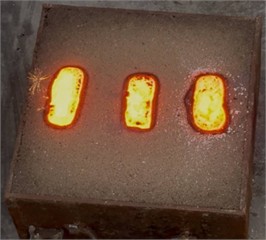
Melting and Pouring. The melting of AISI 1015 steel was performed in an induction crucible furnace (Fig. 4) at a temperature range of 1450-1520 °C. All three samples were cast simultaneously into a sand-clay mold (Fig. 5). Due to the low thermal conductivity of the molding mixture, the cooling rate of the metal was relatively low, which promoted the formation of a well-developed dendritic structure accompanied by component segregation. The application of a bentonite-starch molding mixture ensured a clean casting surface with minimal defects, providing favorable conditions for subsequent metallographic examination [9, 10].
Fig. 1The starting materials for the study are AISI 1015, AISI 321 steel foil, carbon fiber and sodium tetroborate (borax). Photo taken by the authors in the laboratory of the Almalyk Branch of NUST MISIS, 2025
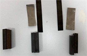
Fig. 2Sandy Clay Form (SCF). Photo taken by the authors in the laboratory of the Almalyk Branch of NUST MISIS, 2025
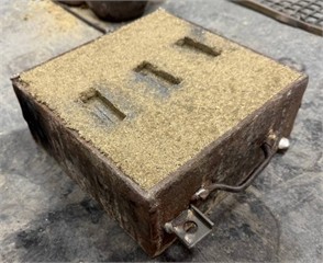
Fig. 3Drying chamber. Photo taken by the authors in the laboratory of the Almalyk Branch of NUST MISIS, 2025
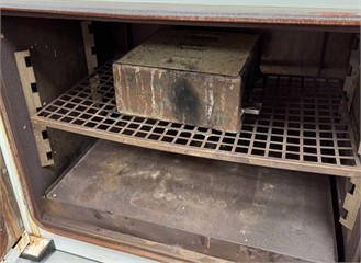
Fig. 4Melting process in an induction crucible furnace. Photo taken by the authors in the laboratory of the Almalyk Branch of NUST MISIS, 2025
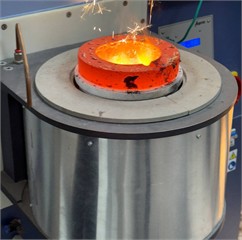
Fig. 5Poured castings in a sand and clay mold. Photo taken by the authors in the laboratory of the Almalyk Branch of NUST MISIS, 2025
When preparing the mold for pouring the second sample, a two-layer substrate consisting of a 0.5 mm thick steel foil and a layer of carbon fiber cloth was used. Such a combination of materials provided a complex thermal regime of crystallization: the foil contributed to intensive heat dissipation at the initial moment of solidification, and the carbon fabric created the effect of thermal insulation at subsequent stages of the process. This led to the formation of a gradient structure with a smooth change in grain size from the surface to the center of the sample [11]. The preparation of the mold for pouring the third sample was the most difficult technological task, as it required the creation of a multilayer system of different materials. The mold base was made of a standard sand mixture, but in the contact zone with the melt a combination of borax, carbon fiber and steel foil was placed. Each of these components performed a specific function: borax acted as a flux that improved the liquid fluidity of the metal, the carbon fabric created a thermal barrier, and the foil provided directional heat dissipation. This combination created unique crystallization conditions that cannot be reproduced using traditional casting methods. The obtained castings were visually inspected for surface defects and then prepared for further studies. The surface quality of all three samples was satisfactory for subsequent metallographic analysis, which confirmed the correctness of the chosen method of mold preparation and casting modes [12].
3. Results and discussion
3.1. Macro- and microstructure
The study of the macrostructure of the samples revealed significant differences in the character of crystallization depending on the pouring conditions. Sample 1, obtained by the traditional method in sand mold, demonstrated a typical dendritic structure with pronounced zonal liquation (Fig. 6). The size of dendrites in the central part of the sample reached 300-400 μm, which is characteristic of slow cooling conditions. At the same time, a zone of columnar crystals about 1 mm thick was observed in the surface layers. Hardness measurements showed values of 50 HRC by Rockwell and 469 HB by Brinell, which corresponds to the expected characteristics for this steel under similar crystallization conditions.
Fig. 6Microstructure of 1 sample. Photo taken by the authors in the laboratory of the Almalyk Branch of NUST MISIS, 2025
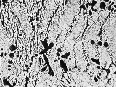
Fig. 7Microstructure of 2 sample. Photo taken by the authors in the laboratory of the Almalyk Branch of NUST MISIS, 2025
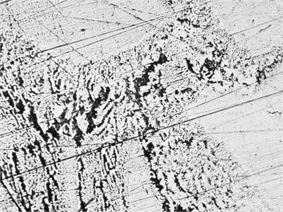
Sample 2 with the combined substrate showed a complex gradient structure. In the foil contact zone (0.6-0.8 mm depth), a fine-grained structure with grain size of 20-30 μm was observed (Fig. 7). The overlying layer, which crystallized under the influence of the carbon fiber, was characterized by 100-150 µm columnar dendrites with an orientation perpendicular to the cooling surface. This structure provided a unique combination of properties: hardness (52 HRC/504 HB) in the surface layer with a gradual decrease to 48 HRC in the central part.
The most interesting results were shown by sample 3 with combined filling. The macrostructure of this sample was characterized by pronounced heterogeneity with clearly distinguishable zones of influence of each substrate component (Fig. 8). The area in contact with borax was characterized by a fine-grained structure with a uniform distribution of carbide phases. The zone with carbon fiber showed the presence of oriented structural elements, which is explained by the anisotropic thermal properties of the material. The highest hardness (55 HRC/552 HB) was recorded in the zone of contact with steel foil, where the combination of intensive heat dissipation and modifying effect of borax led to the formation of sub microcrystalline structure.
Fig. 8Microstructure of 3 sample. Photo taken by the authors in the laboratory of the Almalyk Branch of NUST MISIS, 2025
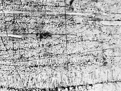
Table 1Comparative analysis
Peening method | Hardness (HRC) | Strength (MPa) | Wear resistance (relative unit) | Resource additions (%) | Service life (h) |
1. Without hardening | 50 | 850 | 1.0 | 0 % | 300-350 |
2. Carbon reinforcement (carbon fiber + foil) | 52 | 900 | 1.3 | 30 % | 400-450 |
3. Composite with borax, foil and carbon fiber) | 55 | 950 | 1.6 | 50 % | 500-600 |
The results of the study confirm the high efficiency of the developed composite carburizing technology. The complex thermochemical environment created by the synergy of foil, carbon fiber and borax provide:
1) Formation of a gradient structure.
2) Reducing the risk of brittleness.
3) Increased hardness while maintaining core toughness.
4) Resistance to impact loads.
Of particular importance is the local saturation of the surface layer without the need for volumetric heating, which simplifies the technology and reduces energy costs.
4. Conclusions
The experimental results demonstrate that the composite carburizing method significantly enhances the performance of excavator bucket teeth. Using a three-component system – carbon fiber, steel foil, and borax – enabled the formation of a fine-grained gradient structure with a surface hardness of up to 55 HRC (552 HB), an increase in wear resistance by up to 60 %, and an extension of service life by approximately 50 % compared to untreated samples. The method also maintained sufficient core toughness while reducing brittleness risk. Owing to its simplicity, reproducibility, and energy efficiency, the technology is recommended for industrial use in mining equipment repair and restoration. Further research is planned to be directed towards optimizing the composite composition for various steel grades and real-world operating conditions.
5. Future scope
The development anresearchtation of composite cementation technology is a promising avenue for enhancing the wear resistance of excavator bucket teeth in harsh mining environments. Future research in this area holds significant potential in several key aspects:
1) Composite carburizing technology presents a promising direction for increasing the wear resistance of excavator bucket teeth, as well as hardening the lining of ball mills and the guide ruler of a ball rolling mill.
2) Further research will focus on adapting the composition of composite materials, in particular the ratio of carbon fiber, replacing steel foil with other alloys, such as titanium, and selecting the correct ratio of borax for different steel grades and operating conditions. This will help improve surface properties with specific performance requirements.
3) As the mining industry transitions to greener technologies, namely minimizing the environmental impact of composite carburizing. Research into alternative heat sources (e.g., induction heating or hybrid methods) and recyclable composite precursors can significantly reduce the energy footprint.
4) Extensive field trials in various mining conditions are needed to validate laboratory results and assess the real-world benefits of the technology. Life cycle cost analysis will help quantify the economic advantages compared to traditional hardening methods.
Thus, the introduction of this technology into the production process of the mining industry can significantly increase the life of bucket teeth, reduce maintenance costs and improve the overall efficiency of excavators in intensive operating conditions.
References
-
P. Gulyaev, Metallurgy. Moscow, Russia: Metallurgy, 1986.
-
Y. M. Lakhtin and V. P. Leontieva, “Materials Science,” in Science News, Vol. 160, Moscow, Russia: Wiley, 2001, pp. 401–401, https://doi.org/10.2307/4012853
-
S. Singla, A. S. Kang, and J. S. Grewal, “Enhancing wear resistance of low alloy steel applicable on excavator bucket teeth via hardfacing,” Asian Review of Mechanical Engineering, Vol. 1, No. 2, pp. 51–54, Nov. 2012, https://doi.org/10.51983/arme-2012.1.2.2295
-
V. G. Zotov and A. N. Ivanov, Restoration of Details by Cladding. Moscow, Russia: Mechanical Engineering, 2008.
-
A. Khrykova, M. Bolsunovskaya, S. Shirokova, and A. Novopashenny, “Implementation of digital signature technology to improve the interaction in company,” in E3S Web of Conferences, Vol. 244, p. 12023, Mar. 2021, https://doi.org/10.1051/e3sconf/202124412023
-
E. E. Kornienko and S. V. Petrov, “Influence of the crystallization conditions on the structure of the clad layer of the high-alloyed steels,” (in Russian), Welding Production, No. 5, pp. 34–41, 2020.
-
V. O. Mirnov, Modern Technologies of Hardening of Working Bodies of Mining Machines. Ekaterinburg, Russia: UGGU, 2019.
-
“High-Alloy Steels and Alloys Corrosion-Resistant, Heat-Resistant and Heat-Resistant,” Standartinform, Moscow, Russia, GOST 5632-2014, 2014.
-
“Standard Test Method for Microindentation Hardness of Materials,” ASTM E384-22, 2022.
-
L. Zhang and H. Wang, “Microstructure and wear resistance of hardfaced excavator teeth,” Journal of Materials Processing Technology, Vol. 291, p. 117045, 2021.
-
B. E. Paton and V. R. Trushchenko, “Advanced hardfacing technologies for mining equipment,” Welding Journal, Vol. 101, No. 3, pp. 45–52, 2022.
-
E. V. Ryzhov, “Restoration of excavator bucket teeth by the combined methods,” (in Russian), Mining Equipment, No. 4, pp. 56–62, 2021.
About this article

The authors have not disclosed any funding.
The datasets generated during and/or analyzed during the current study are available from the corresponding author on reasonable request.
The authors declare that they have no conflict of interest.
