Abstract
The cutting head is a key component of a roadheader’s cutting function, and its design level directly determines the performance of the whole machine to a certain extent. Taking the installation angle of the pick-shaped cutter on the head of the roadheader as a research object, a conversion relationship model between the mounting angle of the cutter and the angle of the cutting function was established. The rock cutting process of the cutting head was simulated by the LS-DYNA finite element software. The simulation model reveals the influence of the angle of teeth on the cutting resistance, load fluctuation and cutting ratio energy consumption. The simulation results show that the cutting resistance decreases gradually with increasing cutting angle. When the cutting angle is greater than 50°, the cutting effect is better. The artificial rock cutting moment determined by the experiment is compared with the simulation results, and the correctness of the established simulation model is verified. This research presents a theoretical basis for the improvement of the cutting performance of the cutting head of a roadheader and provides a theoretical reference for the study of other cutting problems.
1. Introduction
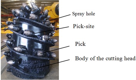
The cutting head is an important part of the rock-breaking function of a roadheader and the most vulnerable part in the whole machine [1, 2]. Its structure includes a head body, an internal spline sleeve, a pick-shaped cutter, a tooth seat, a feed guide plate and a water spray device [3]. The composition of the cutting head is shown in Fig. 1. The cutting head is mainly responsible for axial drilling and radial offset cutting. To ensure easier cutting, more cutting teeth should be involved in cutting at all times [4]. The service life of the pick-shaped cutter directly determines the MTBF (mean time between failures) of the roadheader. The service life of the picks is not simply related to the material of the picks and the model of the picks; the service life of the picks is also inseparable from the arrangement and installation angle of the picks on the cutting head [5, 6].
Fig. 1Composition of the cutting head
At present, domestic and foreign researchers have studied the force of the pick during the cutting process and provided corresponding prediction and calculation methods. The most representative method is the calculation method of the cutting force proposed by foreign scholar Evans in 1961 [7]. The model is based on the ideal cutting conditions of single-tooth plane cutting and symmetrical groove cutting. Ogruoz et al. [8] carried out a comprehensive experimental test of the cutting process, studied the effects of different rock types on the cutting force and the wear of the cutting head, and evaluated the cutting head’s cutting using the specific energy consumption effectiveness. Restner et al. [9] established a finite element model of the cutting machine's cutting process and adjusted the mechanical structure of the machine based on rock properties, cutting speed, turning speed, and cutting depth. SU et al. [10] simulated the cutting process of rock in PFC3D, and the average cutting forces determined by theoretical models, numerical simulations and experiments are relatively close.
Domestic scholars Li Xiaohuo, Liu Chunsheng and others established prediction formulas for cutting resistance based on experiments and theoretical research [11, 12]. At present, although most researchers have used theoretical analysis and experimental tests to analyze the mechanism and force of crushing rock, the consistency of results obtained by different methods is not good. To date, there is no accepted and unified calculation method for calculating the force of rocks [13]. Fu Lin et al. used the dynamic simulation software LS-DYNA to perform a finite element simulation of the cutting process for single-tooth drilling. The calculation results showed that the cutting tooth bears a large feed resistance during the cutting process and that the cutting resistance varies with the cutting. The increase in the angle decreases as a quadratic function [14].
This article takes the installation angle of the pick on the head of the roadheader as the research object and establishes a conversion relationship model between the mounting angle of the pick and the angle of the cutting function. The LS-DYNA finite element software is used to simulate how the cutting head cuts the rock. The process simulation model analyzes the effects of different cutting angles on cutting resistance, load fluctuations and cutting ratio energy consumption and verifies these results through experiments to provide a theoretical reference for selecting the optimal cutting angle for the cutting teeth.
2. Definition of pick mounting angle
2.1. Cutting function angle and installation technology angle
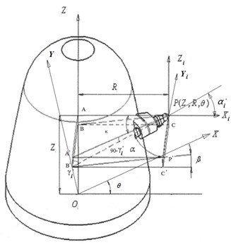
There are 6 degrees of freedom in the pick space for the cutting head of the roadheader, and its position is determined by the coordinates of the tip point (, , ) and the mounting angle of the pick. The tooth point is determined according to the circumferential difference angle of adjacent picks of the same helix and the helix rise angle of the helix. To facilitate the installation of the pick and the analysis of the force, the mounting angle of the pick is defined by the cutting function and the installation process, respectively. The cutting function angle is an angle defined for analyzing the forces and rotation of the cutting teeth during the cutting process, and it indicates whether the cutting teeth cut into the object to be cut with a good attitude. It is defined as the cutting angle , rotation angle , and installation angle . The installation process angle is the angle used when the pick is welded on the cutting head and is defined by the elevation angle , the rotation angle , and the chamfer , as shown in Fig. 2.
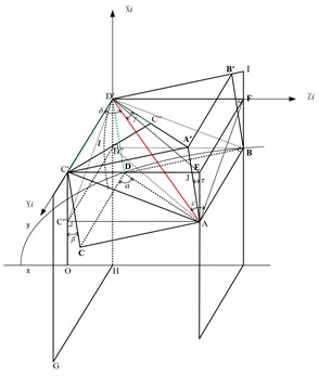
The conversion formula for the cutting function angle and the installation process angle can be derived from Fig. 1. The specific formula is as follows:
The cutting function angle formula is derived from the installation process angle:
The formula for the installation process angle is derived from the cutting function angle:
Fig. 2Schematic diagram of the mounting angle of the pick
2.2. Selection of cutting angle analysis range
Fig. 3 shows the force diagram of the pick cutting force, where is the support force of the rock mass to the pick, is the friction generated by , is the pressure on one side of the pick, is the friction generated by , is the cutting angle of the pick and is the half cone angle of the pick tip.
Fig. 3Force diagram of picks
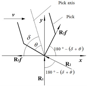
According to the geometric relationships, the expression for the cutting resistance can be obtained:
The cutting angle ranges from 40° to 60°, the half-taper angle of the pick is approximately 40°, and the friction angle is approximately 30°. According to the sine increase and decrease, the cutting resistance decreases as the cutting angle increases.
In the pick arrangement, the selection of the cutting angle should meet two conditions: 1) The tip of the pick tooth should contact the rock formation first; 2) The pick holder should not rub against the rock formation during cutting.
The tip of the tooth cuts into the rock formation first. Due to the high hardness of the pick teeth, the tip of the alloy head is relatively sharp. When cutting the rock layer, the tip of the pick teeth should be sure to cut into the rock layer first. If the teeth of the pick teeth cut first, this situation inevitably leads to serious wear of the teeth, which reduces the life of the pick. The first entry of the alloy head into the rock must meet . The tip of the tooth of the pick alloy head is shown in Fig. 4, and the upper limit of the cutting angle can be obtained:
where: OA – alloy head bus length; – cutting thickness OB; – alloy head extended pick length OD; ∠DOA – pick half cone angle , ∠COB .
Fig. 4Schematic diagram of the cusp point of the pick-tipped alloy head contacting the rock
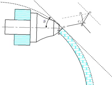
Fig. 5Schematic diagram of picking tooth seat and cutting groove
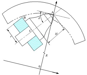
The tooth seat does not rub against the rock formation. A schematic diagram of the tooth base and the trough is shown in Fig. 5. To avoid friction between the tooth base and the rock formation, it is necessary to ensure that point B on the tooth base does not penetrate the trough. It is known that the rotation radius of the tooth tip point is , the distance from the tooth seat to the tooth tip point is , and the radius of the round face of the tooth seat is . To avoid friction between the tooth seat and the rock formation, then , which yields the following formula:
The range of cutting angles can be obtained by calculating the size of the pick and the seat 3456°, and the actual value should be slightly smaller than this value.
3. Simulation analysis
3.1. Specific energy consumption
The specific energy consumption is the energy consumed by the cutting head to cut a unit volume of coal and rock. Its size reflects the cutting efficiency of the roadheader and is one of the indicators to measure the performance of the roadheader. The specific energy consumption is defined as the cutting head cutting energy consumed per unit volume of rock. The calculation formula is as follows:
Assuming that the rock density involved in cutting is the same, we can obtain [15]:
where – cutting rock mass, g; – specific energy consumption, MJ/m3; – rock density, kg/m3; – cut rock volume, mm3; – picks cut unit length, mm.
3.2. Coefficient of variation of pick cutting resistance
The cutting conditions of the roadheader are complicated, resulting in violent vibration and high decibel noise during the work. In severe cases, the whole machine can be immobilized and unable to work normally. Therefore, it is proposed to use the load variation coefficient to reflect the fluctuations in the force of the cutting teeth during work. The cutting resistance variation coefficient is the ratio of the standard deviation of the cutting resistance to the average value of the cutting resistance. The calculation formula for the cutting force fluctuations is [15]:
3.3. Simulation analysis
In the simulation analysis, the rock thickness is 50 mm, the width is 120 mm, the installation parameter of the pick is the axis distance 0, the cutting radius 480, the circumferential angle 0°, the rotation angle 12.3°, and the mounting angle 12°. The cutting angle simulation analysis is shown in Fig. 6, and the material properties of the rocks are shown in Table 1.
Table 1Mechanical parameters of rock materials
Name | Density / (g/mm3) | Elastic modulus / MPa | Poisson’s ratio | Expansion angle / rad | Friction angle / rad | Cohesion / MPa | Compressive strength / MPa | Tensile strength / MPa |
rock | 2.06e-3 | 8038 | 0.28 | 0 | 0.49 | 27 | 97 | 9.9 |
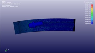
Solving and postprocessing: A pick-cut analysis model is established. The LS-DYNA software is used to solve the problem, and the simulation results of the truncated rock formation are obtained. The stress cloud of the truncated rock formation is shown in Fig. 6.
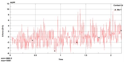
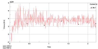
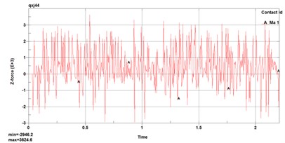
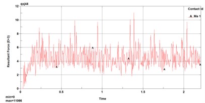
To obtain the cutting resistance of the pick cutting rock layer, the contact force and the total combined contact force of the pick in the -axis, -axis, and -axis directions of the rock layer are extracted in the simulation cutting result file, as shown in Fig. 7.
Fig. 6Stress cloud diagrams of the cut rock layer
The cutting resistance , traction resistance and lateral force can be transformed by the following relationships:
In the formula, is the angle between the tip of the pick and the axis.
Fig. 7Contact force on the pick
4. Analysis of simulation results
4.1. Single tooth cutting simulation
By changing the value of the cutting angle of the cutting head, the changes in the load on the cutting head, the coefficient of load variation, and the energy consumption of the cutting ratio with the cutting angle are analyzed. The range of cutting angle and the calculation results for the cutting resistance, variation coefficient of cutting resistance, and cutting ratio energy consumption are shown in Table 2.
Fig. 8 shows the change in the mean cutting resistance with the cutting angle. The following conclusions can be obtained.
The average cutting resistance of the picks gradually decreases with increasing cutting angle, which changes greatly. When is in the range of 51°-53°, the change in the cutting resistance of the pick is small, and it basically stabilizes. When 53°, the cutting resistance gradually decreases with increasing cutting angle . Therefore, under the condition of ensuring that the tooth seat does not rub against the rock, the larger the cutting angle is, the smaller the cutting resistance, and the better the rock cutting effect.
Table 2Cutting angle and analytical results
Cutting angle | 36° | 40° | 44° | 46° | 48° | 50° | 51° | 52° | 53° | 54° | 55° | 56° |
Cutting resistance / N | 3752 | 3503 | 2766 | 2801 | 2559 | 2310 | 2028 | 1990 | 1990 | 2026 | 1795 | 1685 |
Coefficient of variation | 4.53 | 4.26 | 3.63 | 3.09 | 3.22 | 2.84 | 2.7 | 2.46 | 2.62 | 2.44 | 2.04 | 1.61 |
Specific energy consumption | 2.88 | 3.21 | 2.67 | 2.93 | 2.80 | 2.66 | 2.21 | 2.35 | 2.17 | 2.28 | 2.21 | 2.11 |
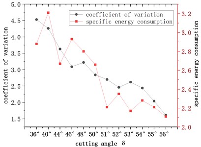
Fig. 9 shows the variations in the cutting resistance variation coefficient and cutting ratio energy consumption with cutting angle. The following conclusions can be obtained.
As the cutting angle increases, the variation coefficient of the cutting resistance gradually decreases. When 51°, as the cutting angle increases, the cutting resistance variation coefficient gradually decreases; when the cutting angle is in the range of 51°-56°, the difference in the cutting resistance variation coefficient values is small. The cutting specific energy consumption gradually decreases with increasing cutting angle. When 50°, the cutting specific energy consumption fluctuates up and down with little change.
Fig. 8Change curve of the mean cutting resistance
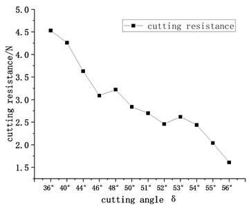
Fig. 9Variation curve of the variation coefficient of the cutting resistance
4.2. Cutting head overall simulation
The cutting head of the roadheader machine is in the cutting state of drilling. The analytical results for the cutting angle are shown in Table 3. It can be seen from the table that the cutting torque gradually decreases with increasing cutting angle and that the fluctuation coefficient of the cutting torque does not change. The quality of the cut rock gradually increases, and the specific energy consumption of cutting gradually decreases.
Table 3Analytical results for cutting angle
Cutting angle | 46° | 50° | 54° |
Cutting moment / N·m | 31835 | 30310 | 28712 |
Cutting moment fluctuation coefficient | 0.31 | 0.33 | 0.27 |
Cutting rock mass / g | 16661 | 19222 | 21462 |
Cut specific energy / MJ·m-3 | 3.8 | 3.2 | 2.7 |
5. Cutting performance test
Experimental bench: An EBZ200 roadheader.
Cutting angle of picks: 50°.
Concrete rock: 8×2×3 m cuboid, compressive strength of 63 MPa.
Measuring equipment: torque sensor, data collector.
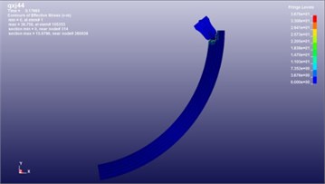
Experimental process: The cutting head of the roadheader performs the cutting test. The cutting process of the cutting head and the measured torque are shown in Fig. 10.
Measurement results and analysis: The cutting moment and load fluctuation coefficient are extracted, and the effect of the cutting angle on the cutting head's rock cutting performance is analyzed through the cutting ratio energy consumption; the results provide guidance and verification for the simulation analysis. The cutting performance measurement and calculation results of the test are shown in Table 4.
Fig. 10Cutting head cutting process and measuring moment
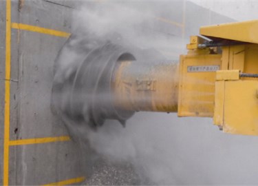

Table 4Experimental results
Cutting angle (°) | Cutting average moment (N.m) | Cutting moment Mz fluctuation coefficient | Specific energy consumption of cutting head (MJ/m3) | Single tooth cutting force (N) |
50 | 1.5x10⁴ | 0.33 | 2.7 | 2596 |
It can be seen from Fig. 10 that the time domain curves of the cutting torque determined by the simulation and the test are relatively close. The cutting torque measured by the test and the simulated cutting torque are on the same order of magnitude, which verifies the correctness of the established finite element model. Table 3 shows that the error between the cutting force of a single tooth and the cutting force of the simulation analysis is approximately 11 %. The torque fluctuation coefficient in the test is similar to the simulated torque fluctuation coefficient.
6. Conclusions
1) The installation angle of the pick is established, and the relationship between the cutting function angle and the installation process angle is determined. The optional range of the cutting angle is analyzed as 34°56°, providing theoretical support for the design and installation of cutting head teeth of a roadheader.
2) A simulation model for analysis of the cutting process of the cutting head of the roadheader is established, and the influence of the cutting angle on the cutting resistance, the coefficient of variation and the energy consumption of the cutting ratio during the rock cutting process is analyzed.
3) The time history curves of the cutting torque are close in the simulation and the experimental measurement, and the average cutting torque is nearly doubled, mainly because the simulation uses full-tooth simulation cutting, and the result is double the experimental measurement value, but it is actually one-half. The cutting teeth of a cutting head participate in cutting; the relative error of the cutting torque fluctuation coefficient is 19 %, the relative error of the cutting specific energy consumption is 16 %, and the average error of the single tooth cutting force is 11 %.
4) In this paper, artificial rocks are used instead of real rocks for simulation and experimental research. If conditions permit, real rocks can be tested to further verify the correctness of the conclusions in this paper.
References
-
Acaroglu O., Ergin H. The effect of cutting head shapes on roadheader stability. Transactions of the Institution of Mining and Metallurgy, Vol. 114, Issue 3, 2005, p. 140-146.
-
Copur H., Ozdemir L., Rostami J. Roadheader Applications in Mining and Tunneling Industries. Preprints-Society of Mining Engineers of AIME, 1998.
-
He Yang, Li Xiaohuo Identification of random cutting load on cutting on cutting head of longitudinal roadheader. Journal of Wuhan University of Science and Technology, Vol. 40, Issue 2, 2017, p. 138-143.
-
Liu S. Y., Chang Long D.-U., Cui X. X., et al. Characteristics of different rocks cut by helical cutting mechanism. Journal of Central South University of Technology, Vol. 18, Issue 5, 2011, p. 1518-1524.
-
Hurt K. G., Mcandrew K. M. Designing Roadheader Cutting Heads. Mining Engineer, 1981.
-
Eyyuboglu E. M., Bolukbasi N. Effects of circumferential pick spacing on boom type roadheader cutting head performance. Tunnelling and Underground Space Technology, Vol. 20, Issue 5, 2005, p. 418-425.
-
Wang Li Ping Calculation of peak cutting force of conical picks under conditions of dissymmetrical slotting. Journal of China Coal Society, Vol. 41, Issue 11, 2016, p. 2876-2882.
-
Dogruoz C., Bolukbasi N. Effect of cutting tool blunting on the performances of various mechanical excavators used in low-and medium-strength rocks. Bulletin of Engineering Geology and the Environment, Vol. 73, Issue 3, 2013, p. 781-789.
-
Restner U., Pichler J., Reumueller B. New technologies extend the range of applications of roadheaders. Symposium on Innovations in Tunnelling, Swiss Federal Institute of Technology Zurich, 2007.
-
Su O., Akcin N. A. Numerical simulation of rock cutting using the discrete element method. International Journal of Rock Mechanics and Mining Sciences, Vol. 48, Issue 3, 2011, p. 434-442.
-
Li Xiaohuo Research on Key Technologies of Roadheader Cutting. China Machine Press, Beijing, 2007.
-
Liu Chun Sheng, Li De Gen Mathematical model of cutting force based on experimental conditions of single pick cutting. Journal of China Coal Society, Vol. 36, Issue 9, 2011, p. 1565-1569.
-
Zhang Mengqi Comparison and analysis of predictor methods for rock breaking resistance of bit. Colliery Mechanical & Electrical Technology, Vol. 41, Issue 11, 2014, p. 2876-2882.
-
Fu Lin, Du Changlong, Liu Songyong, et al. Research on load characteristics of picks on auger drill miner’s aiguille. China Mechanical Engineering, Vol. 24, Issue 15, 2013, p. 2020-2024.
-
Li Xiaohuo Research on Key Skills in TBM Cutting. China Machine Press, Beijing, 2008.
Cited by
About this article

