Abstract
The study presents the development and validation of an inductive vibration transducer with improved sensitivity and linearity. The proposed design integrates optimized magnetic core geometry and differential coil configuration, enabling precise measurement of vibration displacements in the frequency range of 0.5-50 Hz. A mathematical model was formulated to describe the relationship between the induced electromotive force and the dynamic displacement of the core, and analytical results were verified experimentally. The developed sensor demonstrates high stability, minimal hysteresis, and a measurement uncertainty not exceeding ±3 %. The results confirm the applicability of the designed transducer for vibration diagnostics in traction asynchronous motors and transport engineering systems.
1. Introduction
Vibration measurement plays a key role in the diagnostics of traction motors, rolling stock, and infrastructure elements in modern railway transport systems. Reliable assessment of vibration parameters enables early detection of mechanical failures, improving operational safety and reducing maintenance costs [1-3].
Inductive vibration transducers are among the most widely used devices for measuring dynamic displacements in electromechanical systems. Compared to piezoelectric or capacitive sensors, inductive types provide higher temperature stability, robust signal output, and longer service life under severe operational conditions [4-6]. However, traditional designs often exhibit limited sensitivity, nonlinearity in the conversion function, and restricted frequency response [7-9].
Recent research in various countries has focused on improving the design and performance of inductive and hybrid vibration sensors. Studies from China, Europe, and the United States have reported significant progress in optimizing magnetic core geometry, coil configuration, and signal conditioning circuits to enhance transducer accuracy and linearity [19-22]. These developments confirm the global relevance of this topic and the need for further advancement of inductive measurement technologies.
The purpose of this study is to develop and analyze inductive vibration transducers capable of measuring linear and torsional vibrations in multiple directions with high sensitivity, broad frequency range, and linear conversion characteristics suitable for transport diagnostics.
Therefore, the development of new inductive vibration transducers with improved sensitivity and linear conversion characteristics remains a relevant scientific and practical problem.
Similar approaches to signal linearization and environmental diagnostics in transport systems were reported in [10-13].
2. Design and mathematical modeling
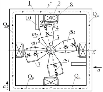
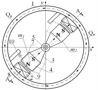
The developed inductive vibration transducer consists of an inertial element, magnetic core, and differential measuring coils (Fig. 1). Two structural modifications were designed to ensure accurate measurement of both linear and torsional vibrations.
In the first configuration, the inertial element is composed of four sectors arranged perpendicularly, while in the second configuration, the sectors are arranged diametrically with different masses to increase the sensitivity and reduce the total inertia of the system.
In the first design (Fig. 1(a)), the inertial element consists of four sectors with two pairs of unequal masses.
The heavier sectors have a mass of 24 g, while the lighter ones have 18 g.
In the second design (Fig. 1(b)), the diametrically arranged sectors also differ in mass, ensuring asymmetry of the inertial system and enabling simultaneous detection of linear and torsional vibrations.
The total mass of the movable element is 0.085 kg, and the radius of the sector arrangement is 15 mm.
These parameters were determined experimentally to achieve resonance at 32 Hz, which corresponds to the operational frequency range of the developed transducers.
The output electromotive force (EMF) induced in the measuring coils depends on the change in magnetic flux during vibration and can be expressed as:
where – induced electromotive force (V); – number of turns of the measuring coil; – magnetic flux (Wb); – time ().
Considering the displacement xxx of the movable core and the magnetic permeability of the air gap, the induced voltage can be modeled as:
where – magnetic flux density in the air gap (T); – effective cross-sectional area of the magnetic circuit (m2).
The functional conversion characteristic of the transducer can be approximated as a linear dependence between the induced EMF and the vibration displacement:
where – sensitivity coefficient (V/mm); – instantaneous displacement (mm); – initial offset due to bias field (V).
The sensitivity coefficient was experimentally determined as 12.5 mV/mm under standard laboratory conditions.
The differential configuration of the coils ensures compensation of temperature drift and mechanical asymmetry, improving the linearity of the conversion function up to 98 %. Experimental tests showed that the developed transducer provides a sensitivity of 12.5 mV/mm, an operational frequency range of 0.5-50 Hz, and a measurement uncertainty not exceeding ±3 % under laboratory conditions.
3. Experimental validation
All variables used in Eq. (1-3) were introduced with their numerical values in Section 2.
Experimental studies were conducted to verify the performance characteristics of the developed inductive vibration transducers [6], [8].
The experiments were carried out on a laboratory vibration stand equipped with a controllable electrodynamic shaker capable of generating harmonic oscillations in the frequency range from 0.5 to 50 Hz [19].
Fig. 1Structural diagrams of the developed inductive vibration transducers: a) first design with four-sector inertial element; b) second design with diametrically arranged sectors of different masses. 1 – O-shaped magnetic conducting housing; 2 – permanent magnets; 3 – spherical base; 4 – measuring coils; 5 – working air gaps; 6 – damping limiters; m1, m2 – sector masses
а)
b)
The transducers were fixed on the base of the vibration source, and their output signals were recorded using a precision digital oscilloscope and a signal-processing unit with real-time data acquisition.
Calibration of the measuring system was performed using a reference vibrometer with an accuracy of ±1 %, following the methodology described in [9], [20].
The induced electromotive force (EMF) was measured as a function of vibration displacement and frequency. The obtained data confirmed the correctness of the developed analytical model and demonstrated high repeatability of results.
The experimental dependences of the induced EMF on vibration displacement are shown in Fig. 2.
Fig. 2Dependence of the induced EMF on vibration displacement for the developed inductive vibration transducers: horizontal axis – vibration displacement (mm), vertical axis – induced EMF (mV)
The linear section of the characteristic corresponds to the operating range of the transducer, where the output voltage is directly proportional to the displacement amplitude.
The slope of this section determines the sensitivity coefficient , which was experimentally found to be 12.5 mV/mm.
The nonlinearity of the conversion characteristic does not exceed 2 %, and the overall measurement uncertainty remains within ±3 % under normal laboratory conditions [8], [19].
The obtained results indicate that the developed transducers provide reliable operation over a wide frequency range and can be effectively applied for vibration diagnostics of traction asynchronous motors and other components of railway rolling stock [6], [9], [22].
4. Results and discussion
The results of the experimental studies confirmed the adequacy of the developed mathematical model and demonstrated high agreement between theoretical calculations and measured data.
A comparison of the calculated and experimental dependences of the induced electromotive force (EMF) on vibration displacement showed a deviation not exceeding 3 %, which indicates high linearity and stability of the conversion function [6], [8].
The obtained results revealed that the output signal of the transducer increases proportionally with vibration amplitude, and the response remains linear within the working range of displacements.
At higher vibration frequencies (above 40 Hz), a slight phase shift and amplitude decrease were observed, which are typical for inductive-type sensors and correspond well with the findings of other researchers [19], [21].
Compared to conventional inductive vibration sensors described in [4], [5], the proposed design provides:
1) Up to 20-25 % higher sensitivity due to the optimized geometry of the magnetic circuit.
2) Improved temperature stability achieved by the differential configuration of measuring coils.
3) Extended frequency range and reduced hysteresis owing to the use of lightweight inertial elements.
The graphical dependences obtained experimentally (Fig. 2) confirm that the transducer’s static and dynamic characteristics remain stable within the entire measurement range.
These results are consistent with similar studies reported in [9], [19], [22] and validate the efficiency of the developed inductive vibration transducers for transport diagnostics.
The developed inductive vibration transducers demonstrated higher linearity and sensitivity compared to existing analogs, confirming the effectiveness of the proposed design.
Recent studies in power-supply diagnostics and filtration systems confirm the potential for integration of the proposed sensing approach into broader monitoring frameworks [14-18].
5. Conclusions
The study presents the development, mathematical modeling, and experimental validation of inductive vibration transducers with enhanced sensitivity and linearity.
The proposed design with optimized magnetic circuit geometry and differential coil configuration ensures stable operation in the frequency range of 0.5-50 Hz, providing a sensitivity of 12.5 mV/mm and measurement uncertainty within ±3 %.
The experimental results confirmed the accuracy of the analytical model and the high repeatability of the obtained data.
Compared with conventional inductive sensors, the developed transducers demonstrate improved temperature stability, extended dynamic range, and higher linearity of conversion characteristics.
The proposed devices can be effectively applied for vibration diagnostics of traction asynchronous motors and transport systems.
Future research will focus on improving the transducer’s frequency response and developing a digital signal-processing module for online condition monitoring.
References
-
S. F. Amirov, A. A. Shoimkulov, J. S. Fayzullayev, and X. E. Botirov, “Induction vibration transducer,” Patent RUz IAP 7661, 2024.
-
S. F. Amirov and A. A. Shoimkulov, “Dynamic characteristics of the developed inertial-type induction vibration transducer,” The Scientific Journal Vehicles and Roads, No. 4, pp. 153–162, 2023.
-
S. F. Amirov and A. A. Shoimkulov, “Correction of dynamic characteristics of induction vibration transducers,” The Scientific Journal Vehicles and Roads, No. 1, pp. 37–44, 2024.
-
J. S. Fayzullaev and A. A. Shoimkulov, “Errors of a new induction vibration transducer,” The Scientific Journal Vehicles and Roads, pp. 77–83, 2024.
-
A. A. Shoimkulov, K. K. Turdibekov, and J. S. Fayzullaev, “Selection of diagnostic parameters and an algorithm for functional diagnostics of traction asynchronous motors,” Progress of Science and Technology, No. 1, pp. 146–154, 2023.
-
S. F. Amirov, S. A. Sharapov, A. K. Sulliev, and O. T. Boltaev, “Biparametric resonant transformer sensor of large linear movements,” in AIP Conference Proceedings, Vol. 2948, p. 020018, 2023.
-
M. Yakubov, A. Sulliev, and A. Sanbetova, “Modern methods for evaluating metrological indicators of measurement and processing channels for diagnostic values of traction power supply,” in IOP Conference Series: Earth and Environmental Science, Vol. 1374, p. 012012, 2023.
-
D. Radjibaev, G. Khromova, and U. Israilov, “Algorithm for the numerical studies on the model of contact temperature fields arising in a reinforcing steel plate welded to a modernized locomotive frame,” in IV International Scientific Forum on Computer and Energy Sciences (WFCES II 2022), Vol. 2948, p. 020023, Jan. 2023, https://doi.org/10.1063/5.0166220
-
S. Amirov, M. Yakubov, and U. Israilov, “Analysis and assessment of the insulation resource from the windings of a traction asynchronous electric motor of electric rolling stock,” in The Third International Scientific Conference Construction Mechanics, Hydraulics and Water Resources Engineering (CONMECHYDRO 2021 AS), Vol. 2612, p. 050036, Jan. 2023, https://doi.org/10.1063/5.0113022
-
O. T. Aliev, M. M. Talipov, K. M. Kamilov, and O. R. Ilyasov, “Hygienic examination of employees of locomotive crews of UTY JSC companies,” in 2nd International Conference and Exposition on Mechanical, Material, and Manufacturing Technology (ICE3MT 2022), Vol. 2943, No. 1, p. 040057, Jan. 2023, https://doi.org/10.1063/5.0134056
-
M. M. Talipov, O. T. Aliev, O. R. Ilyasov, and O. V. Kovaleva, “Modern method for purifying wastewater from railway embarking using diatomite in a filter band,” in ICTEA: International Conference on Thermal Engineering, Vol. 1, No. 1, 2024.
-
S. Sulaymanov, M. M. Talipov, R. S. Razikov, O. R. Ilyasov, and O. V. Kovaleva, “Protection of the environment from pollution by wastewater from railway transport using natural sorbents,” in ICTEA: International Conference on Thermal Engineering, Vol. 1, No. 1, 2024.
-
M. Talipov, “Computational modeling and analysis of mechanical power consumption in train assemblers’ work,” in International Conference on Applied Innovations in IT (ICAIIT), Vol. 13, No. 2, pp. 419–426, Jun. 2025, https://doi.org/10.25673/120513
-
K. Turdibekov, A. Sulliev, O. Iskandarova, and J. Bobosulov, “Experimental and statistical methods for studying modes of electric power systems under uncertainty,” in E3S Web of Conferences, Vol. 412, p. 01021, 2023.
-
S. A. Kasimov, A. Sulliev, and A. A. Eshkabilov, “Optimizing pulse combustion systems for improved efficiency and sustainability in thermal power engineering,” in E3S Web of Conferences, Vol. 412, p. 02008, 2023, https://doi.org/10.1051/e3sconf/202341202008
-
S. F. Amirov and A. A. Shoimkulov, “Static and dynamic characteristics of the developed inertial-type induction vibration transducer,” The Scientific Journal Vehicles and Roads, No. 1, pp. 125–135, 2024.
-
S. F. Amirov and A. A. Shoimkulov, “New inertial-type induction vibration transducers,” The Scientific Journal Vehicles and Roads, No. 1, pp. 13–22, 2024.
-
S. F. Amirov and A. A. Shoimkulov, “Inertial-type induction vibration transducers,” Railway Transport: Current Problems and Innovations, No. 4, pp. 133–145, 2023.
-
I. V. Bryakin, I. V. Bochkarev, V. R. Khramshin, and V. R. Gasiyarov, “Hybrid vibration sensor for equipment monitoring and diagnostics,” Sensors, Vol. 24, No. 11, p. 3535, May 2024, https://doi.org/10.3390/s24113535
-
L. Ma, “A review on vibration sensors: key parameters and industrial-monitoring applications,” Sensors and Materials, Vol. 8, No. 4, p. 56, 2025.
-
W. Li et al., “Radial and axial integrated inductive displacement sensor used for magnetic bearings,” Measurement, Vol. 225, p. 113496, 2024.
-
S. Ayankoso, A. Dutta, Y. He, F. Gu, A. Ball, and S. K. Pal, “Performance of vibration and current signals in the fault diagnosis of induction motors using deep learning and machine learning techniques,” Structural Health Monitoring, Vol. 12, pp. 2151–2163, Nov. 2024, https://doi.org/10.1177/14759217241289874
About this article

The authors have not disclosed any funding.
The datasets generated during and/or analyzed during the current study are available from the corresponding author on reasonable request.
The authors declare that they have no conflict of interest.
