Abstract
The paper presents a method for determining the deformation modulus of soils using a sand pleximeter installed inside a borehole. Radial stresses generated by the compressed sand core produce measurable wall displacements, which form the basis for evaluating the deformation modulus. The limitations of the classical Lamé solution-particularly its overestimation of radial stress decay due to the negligible tensile capacity of soils-are highlighted. To address this, new coordinate functions are proposed and calibrated with laboratory data, showing significantly better agreement with measured stress attenuation. The study also analyzes the corresponding radial displacement fields and outlines practical applications of the obtained modulus in geotechnical design.
Highlights
- The deformation behavior of soils subjected to radial stresses within a borehole is systematically investigated.
- A computational approach is developed for evaluating the stress–strain state of the surrounding soil mass.
- A quantitative relationship between soil deformation and radial pressure is established.
- A nonlinear interaction model of the “borehole–soil” system is proposed, accounting for the mechanical properties of the medium.
- The obtained results can be applied in the design and analysis of drilling operations and geotechnical engineering structures.
1. Introduction
Classical analytical solutions to the axisymmetric problem of a thick-walled cylinder are well documented in the literature [1]. In geotechnical practice, this formulation serves as a fundamental theoretical model for addressing axisymmetric problems encountered in the field. A typical example is its application in the interpretation of pneumatic pressuremeter tests, which are widely used to assess the stress-strain response of soils surrounding an expanding borehole under the influence of the gravitational stress of the ground mass.
A key issue in such analyses concerns the development of tensile stresses and strains in the circumferential direction. Unlike the classical elastic solution for a thick-walled cylinder, soils-owing to their inherently low tensile strength-exhibit either negligible or virtually no tensile stresses and deformations in the tangential direction [2-3]. This fundamental difference between soils and elastic solids has been emphasized in numerous recent studies, which confirm that tensile stress components assumed in classical elasticity models are not physically realized in granular and cohesive geomaterials under in situ conditions [10].
Despite this limitation, the Lamé solution [1] continues to be employed as a theoretical basis for analyzing geotechnical problems involving boreholes subjected to internal pressure. However, when classical Lamé expressions are applied directly to soils, they tend to predict an unrealistically rapid decay of radial stresses with distance from the borehole wall. Recent experimental and analytical investigations conducted after 2015 have demonstrated that such stress attenuation is significantly overestimated by purely elastic models, particularly in soils with negligible tensile capacity [8, 9, 14].
Since soils are incapable of sustaining tensile stresses, the circumferential stress component assumed in the elastic solution cannot fully develop under real field conditions. Consequently, the actual redistribution of stresses around a pressurized borehole differs markedly from classical predictions. This discrepancy leads to systematic errors in the evaluation of radial stress distributions and, ultimately, in the determination of deformation moduli derived from pressuremeter-type tests. Recent studies have therefore highlighted the necessity of introducing modified analytical formulations or experimentally calibrated coordinate functions that explicitly account for the stress transmission mechanisms characteristic of soils rather than elastic solids [13, 15, 16].
2. Research objective
The objective of this study is to develop an improved method for determining the stress-strain state of soil around a borehole under radial pressure. The research aims to refine radial stress distribution models by accounting for the negligible tensile capacity of soils, introduce experimentally validated coordinate functions, and obtain a corrected deformation modulus based on measured radial displacements.
Physical and mechanical properties of the tested loess soil. The experiments were performed on loess soils sampled from the Tashkent region. The main physical properties of the soil at natural moisture content were as follows: Natural moisture content: 18.5-20.2 %; Bulk density: 18.5 kN/m3; Dry density: 15.3 kN/m3; Porosity coefficient: 0.76; Plasticity index: 8.1 %.
These values clearly demonstrate the significant reduction of stiffness due to saturation, which must be considered in the interpretation of radial stress measurements.
The initial stage of testing was carried out on soil specimens at their natural moisture content. After the axial stress reached a stabilized level, the soil inside the borehole was gradually saturated with water until full water-holding capacity was achieved.
According to the calculations based on expression, the deformation modulus for the stiffness coefficient = 3 was obtained as: For natural moisture content: 17.2 MPa; For fully saturated soil: 8.4 MPa.
3. Experiments and analysis
Let us provide a concise overview of the Lamé elastic formulation. Denote the radial strain by (acting in the radial direction of the cylinder) and the tangential or circumferential strain by . The linear strains and corresponding normal stresses develop along three orthogonal directions and are related through the modulus of elasticity as follows: , and . When deformation along the axial direction (the -axis) occurs freely-meaning no external constraints restrict elastic elongation-the axial stress can be assumed to vanish 0.
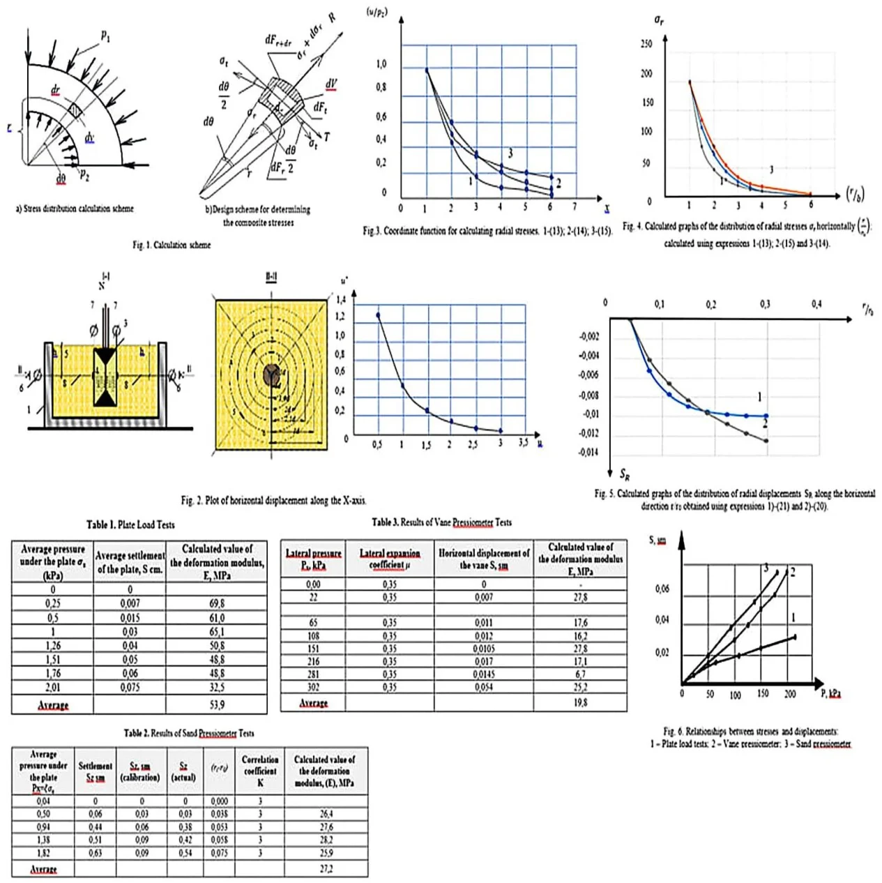
In this analysis, the action of the internal pressure and the external pressure, applied uniformly to the inner and outer surfaces of the pipe, is considered. We denote the outer and inner radii of the pipe by and , respectively. The forces acting on an arbitrarily selected elementary volume due to the applied load are determined see Fig. 1.
Fig. 1Calculation scheme
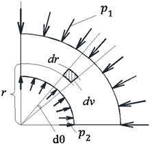
а) Stress distribution calculation scheme
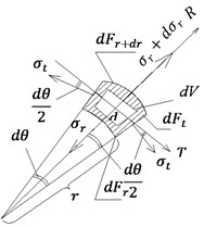
b) Design scheme for determining the composite stresses
We now derive the equation of equilibrium for the radial forces along the -axis.
ADDED clarification: Transition from Eqs. (1) to (2) neglects second-order small terms, typical for axisymmetric equilibrium:
Disregarding quantities of second-order smallness and adopting , we will receive:
Eq. (2) contains two unknown stress components, which makes the problem statically indeterminate and requires an additional constitutive relation. In this scenario, only differential Eq. (2) arises from the equilibrium condition, yet it contains two unknowns, and . Hence, the problem is statically indeterminate.
In the case of soils, based on the theory of strength, the tangential stress is required to satisfy the inequality , with and , representing the soil cohesion and the internal friction angle, respectively. Taking this into account and assuming , differential Eq. (1) becomes homogeneous and can be written in the form:
The assumption 0 reflects the inability of soils to sustain tensile stress and reduces the equilibrium equation to a homogeneous form. In the elastic problem, the differential Eq. (3) has two unknowns and To reduce problem Eq. (2) to a homogeneous form, Hooke’s law is used. A second equation in displacements is formed:
By solving these two equations for and , we can obtain an expression in displacements:
Expression Eq. (5) links the radial and tangential stresses directly to the displacement field, allowing further reduction of the problem to a single differential equation. In Eq. (5), both the radial stress and the tangential stress are expressed in terms of the variable , i.e., the radial displacement at a given radius Fig. 1.
By substituting the stress expressions from Eq. (5) into Eq. (2), a differential equation formulated in terms of displacements is obtained:
The solution of the differential equation for radial displacement is:
Here, and represent the constants of integration. Substituting expression Eq. (7) into Eq. (6) allows the stress components to be explicitly determined:
For the sake of simplicity, new constants, ( and ), are introduced, enabling the last two expressions to be rewritten in the following form:
It can be readily observed that expression Eq. (5) exhibits a form similar to that derived for the plane problem [1]. Using this expression, radial and circumferential (tangential) stresses can be calculated for any chosen value of 𝑟, corresponding to any concentric soil layer surrounding the borehole. The constants 𝐶 and are determined by the boundary conditions. By solving the corresponding equations for 𝐶 and , we find:
Fig. 2Plot of horizontal displacement along the X-axis
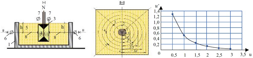
It is well known that the value of , in the context of soils, is determined from the condition of zero displacement over a distance , corresponding to the active compression zone of a concentric soil layer, as determined experimentally . Fig. 3 presents an experimental graph showing the relationship between changes in radial displacement, and normalized displacements, . According to the experimental data, for medium-grain sands, the active compression region is given by . The horizontal external gravitational stress is found from the equality condition:
In this case, , and indicate the soil’s weighted average unit weight and the thickness of the layer, respectively, with k corresponding to the coefficient of lateral earth pressure.
Considering the condition ≅ 0, we examine the solution of the homogeneous differential Eq. (2). The solution of Eq. (3) in its homogeneous form is represented as follows:
where, is the constant of integration, which is determined from the boundary condition at , where . From this, it follows that or . Thus, expression Eq. (12) can finally be written in the form:
According to the results of experimental studies, the following coordinate function meets these requirements:
Fig. 3Coordinate function for calculating radial stresses: 1 – (13); 2 – (14); 3 – (15)
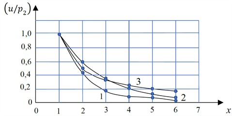
The coordinate function can also be defined by the following phenomenological expression:
where 1.5 is a coefficient determined experimentally. is the active compression region of the soil layer horizontally. For example, for Eq. (13) at .
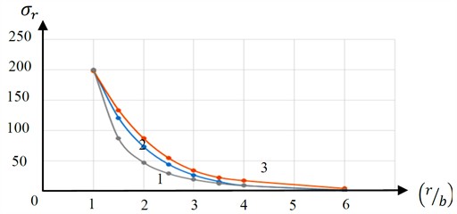
Fig. 4Calculated graphs of the distribution of radial stresses σr horizontally r/r0: calculated using expressions 1 – (13); 2 – (15) and 3 – (14)
or and for Eq. (14) at .
As can be seen from the graph Fig. 4, coordinate functions of the form Eq. (14) and Eq. (15) are closest to the experimental results. The same solution can be obtained from the equilibrium equation:
Thus, it can be stated that for soil, as a medium that does not work under tensile loads, the condition is satisfied , while the value can be conditionally assumed to be . In this case, the stress distribution in the radial direction is directly proportional to the internal pressure and the well radius and inversely proportional to the radius distance . Fig. 5 shows comparative graphs of radial stresses versus relative distance (), obtained using expressions 1-(13); 2-(15) and 3-(14). The calculations were performed for 37.5 mm, 200 kРа. As studies have shown, Eqs. (13 and 14) are the most acceptable for determining the radial stress function.
3.1. Determination of wellbore wall displacements caused by radial stresses
To determine the radial displacements of the borehole wall due to the action of radial stresses acting inside the borehole, , we will use the equation of Hooke’s law for a one-dimensional linear problem:
Let us solve the integral equations for the obtained dependencies (13; 14; 15):
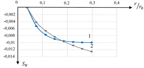
Fig. 5Calculated graphs of the distribution of radial displacements SR along the horizontal direction r/r0 obtained using expressions 1 – (21) and 2 – (20)
And, lastly:
The value is determined depending on the diameter of the well based on the results of experiments for specific types of soil.
The graphs of changes in the functions of radial displacements of the borehole wall are presented in Fig. 6.
From the presented graph Fig. 6 it is evident that the function Eq. (21) more realistically approaches the results of the experimental studies presented in Fig. 5.
Expressions Eqs. (18-21), if the radial displacements are known, allow us to determine the integral value of the deformation modulus:
If the obtained results are compared with the results discussed in Chapter 2, in particular, with expression Eq. (21), then we can conclude that:
In other words, the correction parameter depends on the initial diameter of the well and the active compression region, equal to .
3.2. Comparison of test results obtained using a sand pressuremeter with traditional plate load tests and a vane pressuremeter
The correlation coefficient Eq. (25) for solving practical problems is determined based on comparative results of plate load tests and pressuremeter tests.
To reduce instrument error caused by sand compression under initial pressure, a metal pipe was used in place of the borehole at the beginning of the experiment. Based on the results of these experiments, a calibration graph is constructed showing the relationship between settlement and pressure . The settlement of the sand cylinder is determined taking into account the calibration curve:
where , are the vertical settlements of the sand cylinder inside the borehole corresponding to pressure , ; , are the same values determined from the calibration curve inside the metal pipe.
The deformation modulus for traditional soil testing methods using plate load tests is determined by the following known expression:
Fig. 6Relationships between stresses and displacements: 1 – plate load tests; 2 – vane pressuremeter; 3 – sand pressuremeter
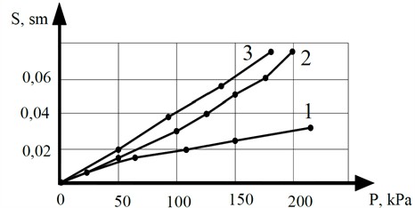
For a circular plate, 0.96. To compare the results of plate load tests, vane pressuremeter tests, and the sand pressuremeter proposed by the authors on slightly moist loess soils, comprehensive tests were conducted. The main physical properties of the soils are: unit weight 17.7 kN/m3; natural moisture content 18.5 %; dry soil unit weight 14.9 kN/m3; porosity coefficient 0.8. The test results are presented in the form of a table and a stress-displacement graph in Fig. 6.
Table 1Plate load tests
Average pressure under the plate (kPa) | Average settlement of the plate, cm | Calculated value of the deformation modulus, , MPa |
0 | 0 | |
0.25 | 0.007 | 69.8 |
0.5 | 0.015 | 61.0 |
1 | 0.03 | 65.1 |
1.26 | 0.04 | 50.8 |
1.51 | 0.05 | 48.8 |
1.76 | 0.06 | 48.8 |
2.01 | 0.075 | 32.5 |
Average | 53.9 |
Table 2Results of sand pressuremeter tests
Average pressure under the plate | Settlement sm | . sm (calibration) | (actual) | () | Correlation coefficient | Calculated value of the deformation modulus. . MPa |
0.04 | 0 | 0 | 0 | 0.000 | 3 | |
0.50 | 0.06 | 0.03 | 0.03 | 0.038 | 3 | 26.4 |
0.94 | 0.44 | 0.06 | 0.38 | 0.053 | 3 | 27.6 |
1.38 | 0.51 | 0.09 | 0.42 | 0.058 | 3 | 28.2 |
1.82 | 0.63 | 0.09 | 0.54 | 0.075 | 3 | 25.9 |
Average | 27.2 |
Table 3Results of vane pressuremeter tests
Lateral pressure . kPa | Lateral expansion coefficient | Horizontal displacement of the vane . sm | Calculated value of the deformation modulus . MPa |
0.00 | 0.35 | 0 | – |
22 | 0.35 | 0.007 | 27.8 |
65 | 0.35 | 0.011 | 17.6 |
108 | 0.35 | 0.012 | 16.2 |
151 | 0.35 | 0.0105 | 27.8 |
216 | 0.35 | 0.017 | 17.1 |
281 | 0.35 | 0.0145 | 6.7 |
302 | 0.35 | 0.054 | 25.2 |
Average | 19.8 |
4. Engineering applications
The proposed approach for determining the deformation modulus under radial loading has several practical applications in geotechnical engineering. First, the refined radial stress distribution and the corresponding deformation modulus can be used in settlement analyses of shallow foundations located near boreholes or underground cavities. Second, the method is directly applicable to the interpretation of pressuremeter test results, where the measured radial expansion of the borehole wall must be related to a representative deformation modulus of the surrounding soil. Third, the obtained stress and displacement fields may be employed in assessing the stability of boreholes in weak or water-saturated soils, where reliable estimates of the deformation characteristics are essential for the choice of casing, drilling parameters and support systems.
5. Conclusions
To determine radial and tangential stresses in a well with internal effective pressure, the use of the equation of elasticity theory Eq. (8) leads to its rapid decrease horizontally, which is not observed in practice.
The closest results were obtained using the classical mechanics method using homogeneous differential equations of the form Eq. (11) and solutions obtained on the basis of experimental studies Eq. (12 and 13).
Expression Eq. (12) was obtained based on experimental results. It has been proven that the value of the active compression region for ground boreholes with an internal effective pressure is approximately equal to .
Expressions Eq. (16), obtained by integrating the function of relative radial deformations, , made it possible to theoretically determine the value of the linear deformation modulus.
A comparison of theoretical expressions for determining the deformation modulus Eq. (20) with known expressions allowed us to determine the physical meaning of the coefficient Eq. (21). It was established that its value depends on the initial borehole diameter and the active compression region equal to . The proposed coordinate functions and the resulting deformation modulus thus provide a more realistic description of the stress-strain behaviour of soils surrounding a pressurized borehole than the classical purely elastic solution.
References
-
G. S. Glushkov and V. A. Sindeev, Course in Strength of Materials. (in Russian), Moscow: Publishing House Higher School, 1965.
-
A. Z. Khasanov and Z. A. Khasanov, Foundations and Foundations on Loess Subsidence Soils. (in Russian), Tashkent: IPTD Uzbekistan, 2006.
-
A. Z. Khasanov and Z. A. Khasanov, Experimental and Theoretical Studies of Soil Strength and Stability. (in Russian), Publishing House Zarafshon, 2015.
-
A. Z. Khasanov and Z. A. Khasanov, Engineering Geology and Soil Mechanics. (in Uzbek), Samarkand: Zarafshon, 2018.
-
A. Z. Khasanov et al., “Priority of application IAP 20170246 dated June 28, 2017. Method for determining the deformation characteristics of soils,” (in Uzbek, Russian), Official Bulletin Tashkent, Vol. 212, No. 12, pp. 30–31, 2018.
-
M. M. Khonkeldiev, “Study of the stress-strain state of foundations made of wet soils under rigid stamps,” (in Russian), MISI, 1981.
-
N. A. Tsytovich, Soil Mechanics. (in Russian), Moscow: Higher School, 1981.
-
Z. Y. Guo, H. N. Wang, and M. J. Jiang, “Elastoplastic analytical investigation of wellbore stability for drilling in methane hydrate-bearing sediments,” Journal of Natural Gas Science and Engineering, Vol. 79, p. 103344, Jul. 2020, https://doi.org/10.1016/j.jngse.2020.103344
-
S. L. Chen and Y. N. Abousleiman, “Wellbore stability analysis using strain hardening and/or softening plasticity models,” International Journal of Rock Mechanics and Mining Sciences, Vol. 93, pp. 260–268, Mar. 2017, https://doi.org/10.1016/j.ijrmms.2017.02.007
-
J. C. Jaeger, N. G. W. Cook, and R. Zimmerman, Fundamentals of Rock Mechanics, 4th Edition. Wiley-Blackwell, 2007, https://doi.org/10.1002/9780470757616
-
J. Huang, M. Jiang, and H. Wang, “An analytical model of time-dependent elastoplasticity with hydraulic-mechanical coupling for wellbore stability in hydrate exploitation,” Marine Georesources and Geotechnology, Vol. 41, No. 12, pp. 1354–1369, Dec. 2023, https://doi.org/10.1080/1064119x.2022.2141160
-
M. Halafawi and L. Avram, “Elastic-plastic solutions for analyzing wellbore stability,” Romanian Journal of Petroleum and Gas Technology, Vol. 3 (74), No. 1, pp. 37–48, Jan. 2022, https://doi.org/10.51865/jpgt.2022.01.04
-
H.-S. Yu, Cavity Expansion Methods in Geomechanics. Dordrecht: Springer Netherlands, 2000, https://doi.org/10.1007/978-94-015-9596-4
-
C. Huang, B. Akbari, and S. Chen, “Quick approximate elastoplastic solutions of wellbore stability problems based on numerical simulation and statistical analysis,” Journal of Natural Gas Science and Engineering, Vol. 51, pp. 147–154, Mar. 2018, https://doi.org/10.1016/j.jngse.2018.01.005
-
J. P. Carter, J. R. Booker, and S. K. Yeung, “Cavity expansion in cohesive frictional soils,” Géotechnique, Vol. 36, No. 3, pp. 349–358, Sep. 1986, https://doi.org/10.1680/geot.1986.36.3.349
-
M. M. Ahmadi and P. K. Robertson, “Evaluation of deformation modulus from pressure meter tests in sand,” Canadian Geotechnical Journal, Vol. 57, No. 9, pp. 1325–1338, 2020.
About this article

The authors have not disclosed any funding.
The datasets generated during and/or analyzed during the current study are available from the corresponding author on reasonable request.
The authors declare that they have no conflict of interest.
