Abstract
The two-dimensional full vector spectrum method is based on dual-channel homologous information fusion, which can only obtain the planar cross-section vibration information of a monitoring point. However, rotor vibration occurs in three-dimensional space, and it is impossible to describe the rotor's vibration conditions in three-dimensional space using only two mutually perpendicular dual-channels. Besides, this limitation may easily lead to the omission of key fault-feature information and result in misdiagnosis. A spatial three-channel homologous information fusion method is proposed to address the above issues. Firstly, the method proves that the rotor’s spatial vortex trajectory remains elliptical in three-dimensional space. Subsequently, the transformation from the spatial coordinate system to the two-dimensional plane coordinate system is achieved through quadratic coordinate transformation, and a specific mapping relationship between any point in the spatial coordinate system and its corresponding point in the two-dimensional plane coordinate system is established. Finally, based on the theory and calculation principle of the two-dimensional full vector spectrum, the extraction of spatial three-dimensional full vector spectrum feature vectors is achieved. The superiority of the spatial three-dimensional full vector spectrum over the two-dimensional full vector spectrum is verified through simulation and experiment.
1. Introduction
Comprehensive characteristic information might not be obtained when monitoring large rotating machinery (such as steam turbines and compressors) using only single-channel vibration information, which can easily lead to misjudgment. The main reasons for this issue are as follows: 1) Single-channel-based signal-processing methods collect only local vibration information in a specific direction of the rotor; the obtained information is often one-sided and incomplete, and cannot reflect the true vibration state of the rotor. 2) Processing the information collected by each sensor separately not only increases workload, but also cuts off the connection information between the two sensors, which may cause the loss of informative characteristics. Information fusion methods are effective in solving the above problems. At present, research on information fusion and its applications is being conducted with unprecedented breadth and depth, but there is no unified classification method for the hierarchical structure of information fusion. The commonly accepted fusion hierarchy is divided into three levels: data-level fusion, feature-level fusion, and decision-level fusion [1]. Data-level fusion refers to the direct fusion of raw data collected by sensors without any processing. The advantage of data-level fusion is that it maximizes the preservation of data features and details. At the end of the last century, significant progress was made in research on information fusion at the data level. For example, Bently Company in America proposed a full-spectrum analysis method based on bidirectional information fusion of rotors with the same cross-section [2]. Qu from Xi’an Jiaotong University proposed the holographic spectrum method for information analysis of rotating machinery [3, 4]. The vibration research institute of Zhengzhou university proposed the full-vector spectrum technology for homologous information fusion of rotating machinery [5, 6], which combines the advantages of both the full-spectrum analysis method and the holographic spectrum method. However, since the 21st century, there have been few reports on research of information fusion technology at the data level. Furthermore, rotor vibration occurs in three-dimensional space, and it is impossible to describe the rotor's vibration conditions in three-dimensional space using only two mutually perpendicular dual-channels. Unfortunately, there is currently a lack of fusion methods for three-channel homologous information at the data level.
With the widespread application of deep learning and its powerful feature-extraction and classification capabilities, fault-diagnosis methods based on multi-channel information fusion and deep learning have made significant progress. Zhang [7] used wavelet time-frequency transform to convert one-dimensional signals into multi-channel time-frequency information, and proposed a rotating-machinery fault-diagnosis method based on multi-channel information fusion and deep transfer learning. Liang et al. proposed a gearbox fault-diagnosis method based on two-dimensional time-frequency information fusion and two-dimensional CNN [8]. He et al. proposed a gearbox fault-diagnosis method based on automatic encoding and fusion of multi-channel information [9]. Chen et al. proposed a fault-diagnosis method based on multi-channel fusion and multi-scale dynamic adaptive residual learning, which effectively improved the accuracy of fault diagnosis for wind-turbine planetary gearboxes [10]. Yang et al. proposed a multi-sensor fusion method based on convolutional neural networks and applied it to bearing fault diagnosis [11]. Chen et al. proposed a multi-condition fault-diagnosis method for planetary gearboxes based on deep fusion of multi-source information [12]. Hou et al. proposed a gearbox fault-diagnosis method based on weighted fusion of multi-channel data and a deep transfer model [13]. Che et al. proposed a rolling-bearing remaining-life prediction method based on complementary empirical mode decomposition and a multi-channel network model by constructing such a model [14]. Cao et al. proposed a complex-domain extension network with multi-channel information fusion to achieve life prediction of rotating machinery under different operating conditions [15]. Zhang et al. developed an intelligent fault-diagnosis model for bearings driven by dual-layer data fusion, which was successfully used for fault-diagnosis of rolling bearings under time-varying operating conditions [16]. Li et al. proposed a rotating-machinery fault-diagnosis method based on a multi-channel fusion covariance matrix and an improved flow model [17]. Bai et al. proposed a rolling-bearing fault-diagnosis strategy based on multi-channel convolutional neural network (MCNN) and multi-scale pruning fusion (MSCF) data-augmentation techniques [18]. Fan et al. proposed a fault-diagnosis method using multi-channel time-frequency information fusion and applied it to planetary-gear fault diagnosis with a small training-sample size [19]. He et al. proposed an integrated transmission convolutional neural network driven by multi-channel signals for intelligent diagnosis of rotating machinery [20]. Yan et al. proposed a multi-channel information-fusion fault-diagnosis method for wind-power drive systems based on multivariate singular spectrum decomposition and improved Kolmogorov complexity [21]. Ma et al. proposed a Lanczos quaternion singular spectrum analysis method for multi-channel information fusion, effectively overcoming the shortcomings of multi-source empirical mode decomposition methods [22]. However, the above methods all belong to information fusion at the feature level or decision level. Although their diagnostic performance is better than that of data-level fusion methods, their interpretability in feature-extraction ability is poor. Besides, their computational efficiency is low, and they are also likely to cause the loss of original information. Recently, as an innovative technology, physical-informed neural networks [24] combine the advantages of physical equations and machine learning to train the “small data” mechanism, effectively improving the interpretability of deep learning in extracting fault features of rotating machinery, they still fall short of data-level fusion methods.
Based on the above, to solve the problem of the two-dimensional full vector spectrum cannot describe the spatial vortex characteristics of a rotor, and to utilize the advantages of data-level information fusion over feature-level and decision-level information fusion in real-time state monitoring, this article proposes a three-channel homologous information fusion method at the data level. The proposed method is not only a further extension of the two-dimensional full vector spectrum technology into three-dimensional space, but also exhibits better performance in fault-feature extraction compared with the two-dimensional full vector spectrum technology. The main innovations of this article are as follows:
1) Extend the two-dimensional full vector spectral feature-extraction algorithm to three-dimensional space, and realize the theoretical derivation and implementation of the three-dimensional full-vector spectral feature-extraction method.
2) Compensate for the lack of fusion research on three-channel homologous information at the data level, which overcomes the shortcoming of the two-dimensional full vector spectrum in describing the rotor's vibration conditions in three-dimensional space.
3) The proposed three-dimensional full vector spectrum homologous information fusion method has been verified through simulation and experiments to be more comprehensive in extracting fault features of monitoring objects compared to the two-dimensional full vector spectrum method, thereby effectively improving diagnostic accuracy.
The remaining chapters of the paper are arranged as follows: Section 2 briefly introduces the theory and algorithm of two-dimensional full vector spectrum. Section 3 provides a detailed introduction to the three-dimensional full vector spectrum and its algorithm implementation. Sections 4 and 5 present simulation and experimental results respectively, which verify the superiority of the three-dimensional full vector spectrum over the two-dimensional full vector spectrum in fault-feature extraction. Section 6 concludes the paper.
2. Two-dimensional planar full vector spectrum
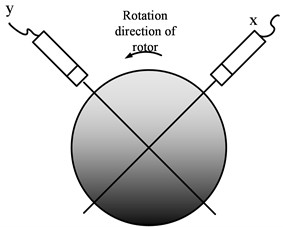
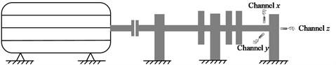
The Jeffcott rotor-sliding bearing system is taken as the research object, and the rotor model is shown in Fig. 1. Dual-channel non-contact eddy-current sensors are arranged in a V-shape, and the arrangement direction of the two sensors is shown in Fig. 2. The and channels are called same-source, and the data collected by the two channels are called dual-channel homologous information.
Fig. 1Rotor model diagram
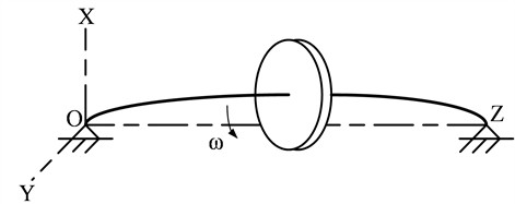
Fig. 2Installation method of two sensors
The rigid rotor with steady-state vortex motion at angular velocity can be equivalent to the disk shown in Fig. 1, and the motion equation at the center of the disk can be written as follows:
where and represent the displacement amplitudes of the rigid-disk center in the directions of and respectively (the motion schematic diagram of the rigid-disk center is shown in Fig. 3), and , . and are the phase angles in the directions of and respectively, and , .
Eliminating in Eq. (1) yields the following motion equation of the disk center:
According to Eq. (2), the motion trajectory of the disk center is an ellipse, as shown in Fig. 4.
Fig. 3Motion schematic diagram of the disc center
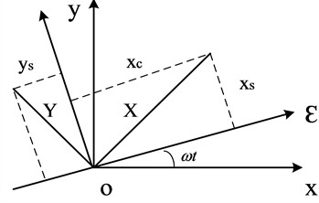
Fig. 4Elliptical motion trajectory of the disk center
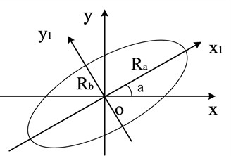
The rotor exhibits vortex phenomena under the combined action of various harmonic frequencies, and its vortex trajectory is a superposition of a series of ellipses, which represent the axis trajectory of the rotor under different rotational harmonics. At each rotational harmonic, the two-dimensional planar full vector spectrum defines the major semi-axis of the ellipse as , called the principal vibration vector at that harmonic. The minor semi-axis is defined as , called the auxiliary vibration vector at that harmonic. The angle between the principal vibration vector and the -axis is , and the phase angle is when the axis moves along an elliptical trajectory. The motion trajectory of the rotor axis under a single harmonic can be uniquely and accurately determined by the above four parameters. The calculation equations for the four parameters are shown in Eqs. (3-6):
Based on Eqs. (3-6), it can be seen that the above four features of the two-dimensional full vector spectral can be obtained by obtaining , , , .
The following equation could be obtained from Eq. (1):
Apply the discrete Fourier transform (DFT) to Eq. (7) yields:
Similarly:
The eigenvalues of the two-dimensional full vector spectral can be obtained by substituting the results from Eqs. (8-9) into Eqs. (3-6).
3. The deduction and calculation process of three-channel space full vector spectrum
The calculation process of three-channel space full vector spectrum is mainly divided into four steps, as follows:
3.1. Step 1: necessity of studying three-channel spatial full vector spectrum
In reality, rotor vibration is a spatial concept. To accurately reflect the spatial vibration of the rotor, it is necessary to add one axial sensor based on Fig. 2 for condition monitoring, i.e., three sensors are required simultaneously. Their specific layout positions are shown in Fig. 5.
Fig. 5Installation method of three sensors
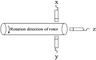
Unfortunately, due to limited installation conditions for axial sensor, the three-sensors application scenario shown in Fig. 5 often has to be simplified to two sensors as shown in Fig. 2, meaning that only vibration information on a certain cross-section of the rotor can be obtained. That is, only dual-channel homologous information fusion can be achieved. However, it is impossible to describe three-dimensional space using only through two mutually perpendicular channels in the same plane. Therefore, three-channel information fusion study based on Fig. 5 is required. Correspondingly, a new spatial three-channel homologous information fusion method based on the two-dimensional full vector spectrum is proposed, and its specific processes are as follows.
3.2. Step 2: proof that the axis trajectory of a rotor at any frequency is elliptical in three-dimensional space
According to the theoretical basis of dual-channel information fusion, the motion equation of a rigid thin-disk rotor with steady-state vortex motion at angular velocity in three-dimensional space can be expressed as following:
in which:
To extend the two-dimensional vector spectrum to a three-dimensional vector spectrum, it is first necessary to prove that the axis trajectory of the rotor at any frequency is an ellipse in three-dimensional space.
In Eq. (10), the following can be obtained when =0:
According to the theory of the two-dimensional full vector spectrum, the motion Eq. (12) describes an ellipse. Due to the symmetry of the coordinate axes of , , , the projection of the three-dimensional axis trajectory of the thin-disk rotor on the coordinate planes , and is an ellipse. Therefore, the trajectory of the disk center must be an ellipse in space or an ellipse lying in a spatial plane.
Let be equal to 0, , respectively, and the three different points , , on the rotor trajectory can be obtained. These three points uniquely determine a plane in three-dimensional space, let its expression be:
Substitute , , into Eq. (13) yield:
Three points determine a plane according to geometric theorems, meaning that Eq. (14) must have a solution. According to linear-algebra knowledge, the equation only has a solution when 0. Therefore, without losing generality, the plane equation can be written as:
Substitute , into Eq. (15), the coefficients and are obtained as follows:
Substituting Eq. (16) into Eq. (15) yields the plane equation. If the axis trajectory is a planar figure, then any point on the trajectory satisfies Eq. (15). Therefore, substituting any point on the rotor axis trajectory from Eq. (10) into Eq. (15) gives the following simplified equation:
It can be seen that the plane Eq. (15) is satisfied by any point on the trajectory of the rotor axis, so the trajectory of the rotor axis in three-dimensional space is a plane curve.
Based on the above analysis, it can be concluded that the projection of the three-dimensional axis trajectory of the thin-disk rotor onto the coordinate planes , and is an ellipse, and the axis trajectory is planar. Therefore, the three-dimensional axis trajectory of the thin-disk rotor is a spatial plane ellipse, and the dual-channel full vector spectrum theory can be used to obtain the three-dimensional axis trajectory.
3.3. Step 3: transformation from the spatial coordinate system to the two-dimensional plane coordinate system
In general, the installation directions of sensors are (radial horizontal), (radial vertical) and (axial). If the spatial plane containing the axis trajectory is , and is perpendicular to and passes through the center of the elliptical trajectory, then any point in the coordinate system where the axis trajectory lies can be transformed into point in the coordinate system after coordinate change, satisfying , that is . If and are considered as and in dual-channel information fusion, we can use dual-channel full vector spectrum knowledge to calculate the three-dimensional axis trajectory.
Fig. 6The two transformations from coordinate system xyz to x'y'z': a) the first transformation of coordinate system; b) the second transformation of coordinate system
a)
b)
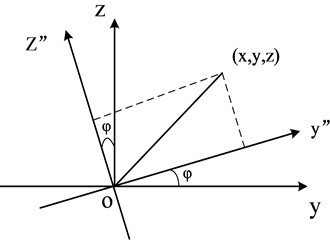
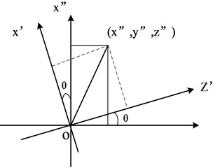
As shown in Fig. 6, the transformation from coordinate system to can be carried out in two steps:
Firstly, rotate by an angle around the -axis to obtain coordinate system .
Secondly, rotate by an angle around the -axis to obtain coordinate system .
By finding appropriate intermediate parameters and , the trajectory represented in the spatial coordinate system can be transformed onto the coordinate plane after the above two coordinate transformations.
Transformation from to :
Let be any point in coordinate system , it becomes after transforming from to , where the -axis remains unchanged and both axes and rotate counterclockwise by an angle . According to the coordinate rotation theorem, the transformation relationship is:
Transformation from to :
Let be any point in coordinate system , it becomes after transforming from to , where the -axis remains unchanged and both the and axes rotate counterclockwise by angle . According to the coordinate rotation theorem, the transformation relationship is:
Combining the two transformations yields the overall coordinate transformation relationship:
Because the trajectory is planar, , i.e.:
Then:
Substitute Eq. (22) into Eq. (20) and simplify yield:
Substitute Eq. (10) into Eq. (23) gives the motion equations for and :
Suppose:
Then the motion equations of and can be written as:
3.4. Step 4: extraction of spatial three-dimensional full vector spectrum feature vectors
Eq. (26) is the axis trajectory equation of the rotor on the trajectory plane, where , , , are independent of and . Based on the dual-channel full vector spectrum theory, if , , , are regarded as , , , in the dual-channel vector spectrum theory, the axis trajectory of the rotor in three-dimensional space can be calculated using the dual-channel vector spectrum formulas. The calculation formulas for the three-channel vector spectrum feature vector can be obtained as follows:
According to Eqs. (27-30), obtaining , , , yields the three-channel vector spectrum feature vector , , , . Therefore, the parameters and need to be determined to calculate , , , .
The calculation of parameter : From the coordinate transformation process, is the angle between the intersection line of the trajectory plane with the plane and the -axis. The equation for the intersection line of plane and coordinate plane is , so the angle can be expressed as:
in which:
The calculation of angle : Based on the coordinate transformation process, is the angle between the trajectory plane and . The trajectory plane is obtained by coefficients and . The equation for coordinate plane is , and angle is obtained as:
At this point, all characteristic formulas for the elliptical motion of the rotor center along the spatial plane have been obtained. In addition, only , , , , , need to be determined to obtain all the above-mentioned feature vectors of the three-dimensional full vector spectral.
The following equation can be obtained based on Eq. (10):
Applying DFT to Eq. (33):
Similarly:
The three-dimensional full vector spectral feature vector , , , can be obtained by substituting the obtained , , , , , into Eq. (25) and Eqs. (27-30).
4. Simulation
The same-source three-channel information of a large rotor in the same spatial section is simulated using Eq. (36), with signal unit in μm (micrometers). Assume the alarm value of the unit is 100 μm and the danger value is 130 μm, the highest analysis frequency is set as 200 Hz. The sampling frequency for the simulated signals is set as 2.56×200 = 512 Hz, and the number of sampling points is set to 512:
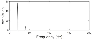
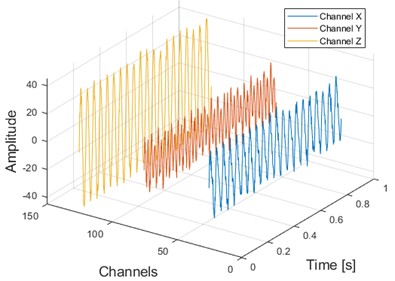
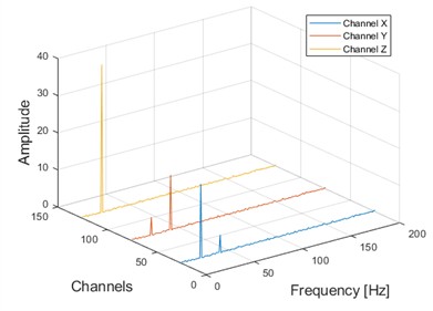
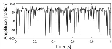
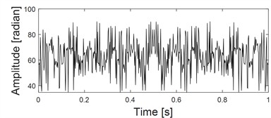
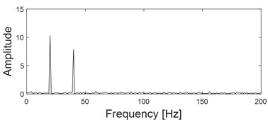
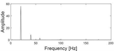
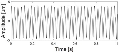
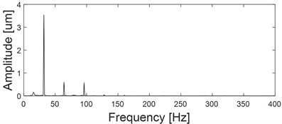
The waveform, spectrum, planar dual-channel full vector spectrum, and spatial three-channel full vector spectrum of the three-channel simulation signals are shown in Fig. 7. The peak-to-peak (PP) values can be obtained from the three signals' waveform diagrams are 44 μm, 36 μm, and 80 μm, respectively. According to the above alarm values, the vibration amplitude is below the alarm value, and the rotor is operating normally. The vibration amplitude also does not exceed the standard based on the two-dimensional full vector spectrum. However, based on the three-dimensional full vector spectrum, the vibration amplitude is 58×2 = 116 μm, which has exceeded the alarm value, consistent with the real situation. Furthermore, it is indeed easy to make misjudgments when analyzing from a single direction: the 1X amplitude of the -direction vibration is dominant, suggesting an unbalance fault. The vibration in the y-direction is mainly characterized by 1X and 2X, and the amplitude of 2X is greater than that of 1X, indicating a misalignment fault. Besides, the possibility of misalignment appears higher based on the two-dimensional full vector spectrum. However, in this case, the axial vibration is particularly large, which largely indicates that the rotor has experienced an imbalance fault. From the perspective of the three-dimensional full vector spectrum, spatial energy is mainly concentrated at 1X, which is generally caused by rotor imbalance, bearing damage, etc. Considering that there are no high-frequency vibration components in the three-dimensional full vector spectrum, rotor imbalance fault is further diagnosed, consistent with the actual situation.
Besides, the calculation time for the results shown in Fig. 7(e) and Fig. 7(f) are 4.8 seconds and 5.2 seconds respectively, both run using Matlab2016 on hardware with an Intel Core i7-10700K CPU and an NVIDIA RTX 3080 GPU. Through the above statistical comparison of calculation time, it can be seen that the proposed method does not cause a significant decrease in computational efficiency due to intermediate coordinate transformation.
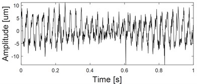
To verify the robustness of the proposed method against noise, random noise is added into the three-channel signals shown in Fig. 7(a). The signal-to-noise ratios of the three-channel signals after noise addition are 6 dB, 5 dB, and 8 dB, respectively. The time-domain waveform of the noisy signals are shown in Fig. 8 (a). The analysis process and final results of the proposed method are illustrated in Figs. 8(b-f). As shown in Fig. 8(f), the method can effectively extract its alarm features even under noise influence.
In summary, the three-dimensional full vector spectrum can reflect the rotor’s vibration situation in space, which is very convenient for more reliable and accurate monitoring of the unit.
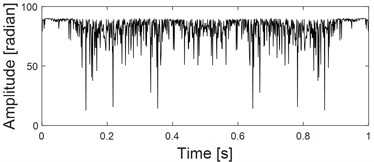
Fig. 7Three-channel simulation signals and their planar and spatial principal vector characteristics: a) time domain diagrams of the same source three-channel simulation signals; b) frequency domain diagrams of the same source three-channel simulation signals; c) the first rotation angle θ from three-dimensional coordinates to two-dimensional coordinates transformation; d) the second rotation angle φ from three-dimensional coordinates to two-dimensional coordinates transformation; e) principal vibration vector of xy dual-channel plane full vector spectrum; f) the principal vibration vector of the spatial full vector spectrum of the xyz three-channel channel
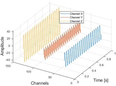
a)
b)
c)
d)
e)
f)
5. Experiment
The picture of the rotor test bench is shown in Fig. 9(a), which is taken by the author in the school of Applied Technology, Huanghe Science and Technology University on October 5, 2025. A plastic cylinder is set up to generate rubbing faults, and the rotor of the test bench is driven by an asynchronous motor. The rotor system is supported by three sliding bearings with the same structure, and three disks are arranged in the middle of the rotor, which can be used to simulate single-sided and multi-sided rotor imbalance by adding unbalanced mass blocks on the disks. The natural frequency of the rotor is about 2600 r/min, and the natural frequency of the bearing system is 3600 r/min. Three eddy-current sensors of the same model are arranged at the shaft neck of the rotor test bench, the layout details are shown in Fig. 9(b). The power-supply range of the sensors is from –17.5 V DC to –26 V DC, with a linear measurement range of 2 mm and a sensitivity of 7.874 V/mm. The relative displacement signals at the shaft neck are obtained through the acquisition instrument. The experimental speed is set as 1800 r/min, and the sampling frequency is set as 1024 Hz.
Fig. 8three-channel simulation signals with noise and their planar and spatial principal vector characteristics: a) Time domain diagrams of the same source three-channel simulation signals with noise; b) Frequency domain diagrams of the same source three-channel simulation signals with noise; c) The first rotation angle θ from three-dimensional coordinates to two-dimensional coordinates transformation; d) The second rotation angle φ from three-dimensional coordinates to two-dimensional coordinates transformation; e) Principal vibration vector of xy dual-channel plane full vector spectrum; f) The principal vibration vector of the spatial full vector spectrum of the xyz three-channel channel
a)
b)
c)
d)
e)
f)
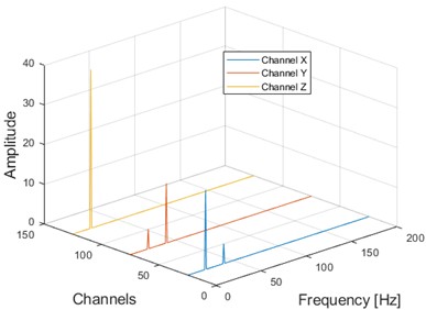
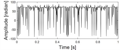
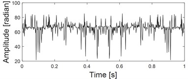
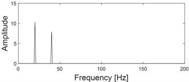
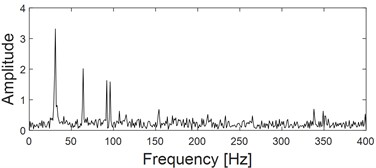
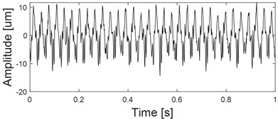
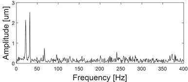
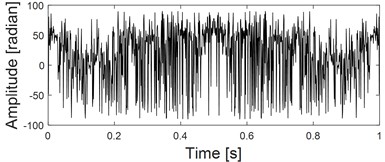
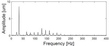
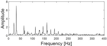
The time-domain waveform of the signals in the , , and directions are shown in Fig. 10(a), (c), and (e) respectively, and the corresponding spectrograms are shown in Fig. 10(b), (d), and (f). The -direction signal is clearly dominated by 1X and accompanied by indistinct 2X and 3X features, consistent with the characteristics of unbalanced fault. The signal in the -direction is mainly dominated by 1X and accompanied by obvious 2X and 3X features, consistent with the characteristics of a basic loosening fault. The -direction information is mainly dominated by 1X and accompanied by obvious fractional harmonics. If fault-diagnosis is based on the features of the three channel signals separately, vastly different fault-diagnosis conclusions will be drawn. The principle vibration vector spectrum features by applying two-dimensional full vector spectrum analysis to the signals in the x and y directions are shown in Fig. 10(i), based on this, it can be seen that the 1X feature is further enhanced, and the 2X, 3X, and high-order harmonic component features are enhanced. However, to diagnose a rubbing fault, fractional harmonic features are still required. The three-dimensional full vector spectral principal vector features obtained by fusing the , , and channel signals based on the proposed method are shown in Fig. 10(j), based on this, not only the 1X and its high-order integer multiple harmonic components are extracted, but also the fractional-multiple harmonic components are effectively extracted, thus obtaining the diagnostic conclusion of a rubbing fault.
Fig. 9The test bench and the layout of the three sensors: a) the picture of the test bench; b) schematic diagram of the three sensors’ layout
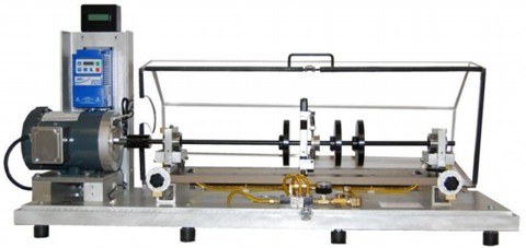
a)
b)
To quantify the superiority of fractional-frequency features in Fig. 10(j), the energy ratio of the fractional harmonic components to the overall amplitude is defined, as shown in Eq. (37), where Fractional Harmonic Energy Ratio (FHER) is the sum of all amplitudes in the spectrum from 0-1X divided by the overall amplitude. After calculation, the Fractional Harmonic Energy Ratio value of Fig. 10(j) is about 9.6 times that of Fig. 10(i):
It should be pointed out that this experiment is a rotor-bearing rubbing experiment. In the two-dimensional and three-dimensional full vector analysis results, the fault characteristics of principal vibration vector are mainly 1X, and fractional harmonic components below 1X also appear (as shown in Fig. 10(i) and (j)). The simulation simulates the rotor unbalance fault, and the fault characteristics of principal vibration vector are mainly 1X (as shown in Fig. 7(i) and (j)).
Fig. 10three-channel experiment signals and their planar and spatial principal vector characteristics: a) time-domain waveform of x channel; b) frequency-domain waveform of x channel; c) time-domain waveform of y channel; d) frequency-domain waveform of y channel; e) time-domain waveform of z channel; f) frequency-domain waveform of z channel; g) the first rotation angle θ from three-dimensional coordinates to two-dimensional coordinates transformation; h) the second rotation angle φ from three-dimensional coordinates to two-dimensional coordinates transformation; i) the principal vibration vector of xy dual-channel plane full vector spectrum; j) the principal vibration vector of the spatial full vector spectrum of the xyz three-channel channel
a)
b)
c)
d)
e)
f)
g)
h)
i)
j)
Based on the above analysis, it can be seen that, on the basis of the original two-dimensional full vector spectrum analysis, the three-channel full vector spectrum features can effectively compensate for the problem of missing effective information in two-dimensional full vector spectrum by fusing -channel information, and provide useful assistance in improving the accuracy of fault diagnosis for large rotating machinery.
6. Conclusions
This article first proves that the rotor space vortex trajectory remains a plane ellipse in three-dimensional space through quadratic coordinate transformation, and derives the specific calculation formulas for the two flipping angles of the quadratic coordinate transformation. Based on the rotation angles, the relationship between the three-dimensional full vector spectral feature vector and the two-dimensional full vector spectral feature vector is established, and then the three-dimensional full vector spectral theory and algorithm are proposed. The following conclusions are drawn through simulation and experimentation:
1) The simulation of rotor unbalance faults shows that the proposed three-dimensional full vector spectrum algorithm effectively integrates -channel information based on two-dimensional full vector spectrum algorithm, which can more effectively enhance the characteristics of unbalance faults and improve the accuracy of fault diagnosis.
2) The analysis results of the rubbing-fault experiment on the rotor test bench show that the proposed three-dimensional full vector spectrum analysis method effectively integrates three-channel information. Compared with the two-dimensional full vector spectrum analysis method, it can not only effectively enhance the integer-multiple harmonic characteristics of rubbing fault, but also effectively enhance the fractional-multiple harmonic characteristics of rubbing fault.
The three-dimensional full vector spectrum algorithm is not only an effective extension of the two-dimensional full vector spectrum, but also has higher computational efficiency compared to deep-learning feature-extraction methods, providing a new technology for accurate fault diagnosis in practical engineering of large rotating machinery.
References
-
H. J. Wang et al., “Condition recognition model based on multi-source information fusion for high-end CNC equipment,” (in Chinese), Chinese Journal of Scientific Instrument, Vol. 39, No. 4, pp. 61–66, Apr. 2018, https://doi.org/10.19650/j.cnki.cjsi.j1702722
-
W. Fengqi and G. Meng, “Compound rub malfunctions feature extraction based on full-spectrum cascade analysis and SVM,” Mechanical Systems and Signal Processing, Vol. 20, No. 8, pp. 2007–2021, Nov. 2006, https://doi.org/10.1016/j.ymssp.2005.10.004
-
F. L. Geng, F. C. Li, and G. Meng, “Research on fault-diagnosis using 2-D holospectrum for rotating machinery,” Mechanical Science and Technology for Aerospece Engineering, Vol. 33, No. 10, pp. 1445–1449, Oct. 2014.
-
S. Liu and L. S. Qu, “fault-diagnosis prior the field balancing based on holgspectrum,” (in Chinese), Journal of Vibration Measurement and Diagnosis, Vol. 24, No. 4, pp. 270–274, Dec. 2004, https://doi.org/10.16450/j.cnki.issn.1004-6801.2004.04.004
-
X. L. Chen and J. Han, “On rotation phase of a rotating machinery by full vector spectrum and its applications,” (in Chinese), Mechanical Science and Technology for Aerospace Engineering, Vol. 27, No. 4, pp. 515–519, Feb. 2008, https://doi.org/10.13433/j.cnki.1003-8728.2008.04.030
-
X. L. Jin, “The instantaneous power spectrum analysis of nonstationary random vibration signals,” (in Chinese), Journal of Vibration Engineering, Vol. 3, No. 3, pp. 25–31, Aug. 2006, https://doi.org/10.16385/j.cnki.issn.1004-4523.1990.03.004
-
L. Zhang et al., “Multichannel information fusion and deep transfer learning for rotating machinery fault-diagnosis,” (in Chinese), China Mechanical Engineering, Vol. 34, No. 8, pp. 966–975, May 2023, https://doi.org/10.3969/j.issn.1004-132x.2023.08.011
-
R. J. Liang et al., “Recognition of gearbox operation fault state based on CWT-CNN,” (in Chinese), Journal of Aerospace Power, Vol. 36, No. 12, pp. 2465–2473, Nov. 2021, https://doi.org/10.13224/j.cnki.jasp.20210450
-
Z. He, H. Shao, Z. Ding, H. Jiang, and J. Cheng, “Modified deep autoencoder driven by multisource parameters for fault transfer prognosis of aeroengine,” IEEE Transactions on Industrial Electronics, Vol. 69, No. 1, pp. 845–855, Jan. 2022, https://doi.org/10.1109/tie.2021.3050382
-
Q. Chen, C. Z. Chen, and W. J. An, “Fault-diagnosis of planetary gearbox based on multi-channel fusion and multi-scale adaptive residual learning,” (in Chinese), Journal of Mechanical and Electrical Engineering, Vol. 40, No. 7, pp. 1031–1038, Jul. 2023, https://doi.org/10.3969/j.issn.1001-4551.2023.07.008
-
J. Yang et al., “Aeroengine bearing fault-diagnosis based on convolutional neural network for multi-sensor information fusion,” (in Chinese), Proceeding of the CSEE, Vol. 42, No. 13, pp. 4933–4942, Jul. 2022, https://doi.org/10.13334/j.0258-8013.pcsee.211097
-
R. X. Chen et al., “Planetary gearbox fault-diagnosis technique based on multi-source information deep fusion,” (in Chinese), Journal of Vibration Engineering, Vol. 33, No. 5, pp. 1094–1102, Nov. 2020, https://doi.org/10.16385/j.cnki.issn.1004-4523.2020.05.024
-
Z. G. Hou et al., “Gearbox fault-diagnosis based on transfer learning and weighted multi-channel fusion,” (in Chinese), Journal of Vibration and Shock, Vol. 42, No. 9, pp. 236–246, May 2023, https://doi.org/10.13465/j.cnki.jvs.2023.09.027
-
L. Y. Che, J. W. Gao, and H. C. Fu, “Residual life prediction of rolling bearings based on multi-feature fusion,” (in Chinese), Journal of Electronic Measurement and Instrumentation, Vol. 37, No. 12, pp. 225–233, Mar. 2024, https://doi.org/10.13382/j.jemi.b2306804
-
Y. Cao, M. Jia, Y. Ding, X. Zhao, P. Ding, and L. Gu, “Complex domain extension network with multi-channels information fusion for remaining useful life prediction of rotating machinery,” Mechanical Systems and Signal Processing, Vol. 192, p. 110190, Jun. 2023, https://doi.org/10.1016/j.ymssp.2023.110190
-
Z. Zhang, Z. Jiao, Y. Li, M. Shao, and X. Dai, “Intelligent fault diagnosis of bearings driven by double-level data fusion based on multichannel sample fusion and feature fusion under time-varying speed conditions,” Reliability Engineering and System Safety, Vol. 251, p. 110362, Nov. 2024, https://doi.org/10.1016/j.ress.2024.110362
-
X. Li, Y. Yang, N. Hu, Z. Cheng, H. Shao, and J. Cheng, “Maximum margin Riemannian manifold-based hyperdisk for fault diagnosis of roller bearing with multi-channel fusion covariance matrix,” Advanced Engineering Informatics, Vol. 51, p. 101513, Jan. 2022, https://doi.org/10.1016/j.aei.2021.101513
-
R. Bai, Q. Xu, Z. Meng, L. Cao, K. Xing, and F. Fan, “Rolling bearing fault diagnosis based on multi-channel convolution neural network and multi-scale clipping fusion data augmentation,” Measurement, Vol. 184, p. 109885, Nov. 2021, https://doi.org/10.1016/j.measurement.2021.109885
-
H. Fan et al., “A novel intelligent fault diagnosis method of helical gear with multi-channel information fused images under small samples,” Applied Acoustics, Vol. 228, p. 110357, Jan. 2025, https://doi.org/10.1016/j.apacoust.2024.110357
-
Z. He, H. Shao, X. Zhong, and X. Zhao, “Ensemble transfer CNNs driven by multi-channel signals for fault diagnosis of rotating machinery cross working conditions,” Knowledge-Based Systems, Vol. 207, p. 106396, Nov. 2020, https://doi.org/10.1016/j.knosys.2020.106396
-
X. Yan, Y. Liu, Y. Xu, and M. Jia, “Multichannel fault diagnosis of wind turbine driving system using multivariate singular spectrum decomposition and improved Kolmogorov complexity,” Renewable Energy, Vol. 170, pp. 724–748, Jun. 2021, https://doi.org/10.1016/j.renene.2021.02.011
-
Y. Ma, J. Cheng, P. Wang, J. Wang, and Y. Yang, “A novel Lanczos quaternion singular spectrum analysis method and its application to bevel gear fault diagnosis with multi-channel signals,” Mechanical Systems and Signal Processing, Vol. 168, p. 108679, Apr. 2022, https://doi.org/10.1016/j.ymssp.2021.108679
-
M. Raissi, P. Perdikaris, and G. E. Karniadakis, “Physics-informed neural networks: a deep learning framework for solving forward and inverse problems involving nonlinear partial differential equations,” Journal of Computational Physics, Vol. 378, pp. 686–707, Feb. 2019, https://doi.org/10.1016/j.jcp.2018.10.045
About this article

The paper is supported by the Design and Research on Internal Inspection and Detection Platform for Large Spherical Storage Tanks (approved grant: 24022008).
The datasets generated during and/or analyzed during the current study are available from the corresponding author on reasonable request.
The authors declare that they have no conflict of interest.
