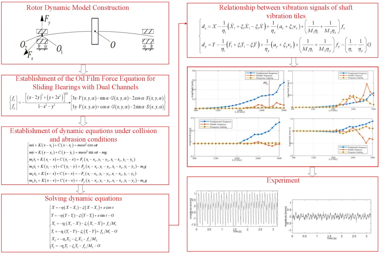
Abstract
Shaft vibration (displacement signal) and bearing vibration (velocity signal) are key indicators for evaluating the dynamic characteristics of the rotor and supporting bearing system, and they play a crucial role in the operational performance and safety of equipment. However, in practical applications, collecting shaft vibration or bearing vibration signals often encounters multiple challenges, primarily attributed to limitations in measurement technology, interference from faults, and variations in operating environments. In-depth investigation into the intrinsic correlation between shaft vibration and bearing vibration not only enables data supplementation to improve information completeness, but also offers more precise references for fault diagnosis and condition monitoring. Therefore, this study proposes a method based on homologous information fusion, aiming to explore the intrinsic correlation between shaft vibration and bearing vibration under rub-impact faults. The study first constructs a dynamic model under rub-impact fault condition, and then fuses homologous information using full vector spectrum technology to improve the accuracy of determining the relationship between shaft vibration and bearing vibration at different rotational speeds. Finally, the reliability of simulation results is validated through the establishment of a rotor experimental rig. Experimental results reveal that by mastering this complementary relationship, the operating health status of equipment can be inferred based on the variation tendencies of other critical parameters – even when a specific measured signal is unavailable – and corresponding maintenance and management strategies can thus be formulated.
Highlights
- A more refined dynamic model under rub-impact fault condition is developed, and the interaction between shaft vibration and bearing vibration under rubbing condition is studied systematically based on the full vector spectrum analysis method.
- A rotor experimental platform is built to further verify the interaction between shaft vibration and bearing vibration under rub-impact conditions.
- A systematic and in-depth analysis is performed on the intrinsic correlation between shaft vibration and bearing vibration under different influencing factors by using the full vector spectrum analysis method, providing richer support for the assessment of equipment health status.
1. Introduction
In the operation of modern mechanical equipment, shaft vibration and bearing vibration serve as critical indicators that characterize the operational stability and reliability of the equipment. Due to the inevitable occurrence of rub-impact faults during manufacturing and operation, as well as the limitations of measurement devices and the complexity of service conditions, it is difficult to simultaneously acquire the relevant signals of shaft vibration and bearing vibration. Therefore, conducting in-depth research on the correlation between these two types of vibrations under rub-impact fault condition is particularly crucial, as this study holds significant engineering importance for ensuring the stable operation of rotating mechanical equipment.
Many scholars have conducted relevant research on shaft vibration or bearing vibration. For example, Jiang et al. [1] explored the correlation between shaft vibration and abnormal temperature variations, and their findings indicated that the underlying issue stems from inadequate sphericity and improper clearance parameters. Xuan et al. [2] found that segmented start-up can reduce the instability of mixed-flow pumps, while friction between the rotor and bearings can lead to high-order harmonic components within a specific frequency interval of the shaft vibration spectrum. Li et al. [3] investigated the impact of deep peak-shaving operating conditions on shaft vibration, providing a valuable reference for similar fault diagnosis. However, their research lacks an in-depth exploration of the underlying causes of such faults. Zhu et al. [4] carried out a systematic investigation into the shaft vibration issues of WX generators, and their research revealed that lowering the vibration amplitude holds substantial engineering significance. Yang et al. [5] revealed the coupling mechanism of shaft vibration in RSDB systems, but only limited experimental verification was conducted. Tian et al. [6] adopted CEEMDAN, permutation entropy, and mathematical morphology for denoising shaft vibration signals, achieving better performance than the wavelet soft thresholding method. Xu et al. [7] elaborated on the causes of unstable shaft vibration signals, and their analysis indicated that the underlying issue originates from poor contact induced by contaminated joints. Tao et al. [8] investigated the influence of shaft vibration on tooth surface ripples via frequency-domain comparison, yet their research lacks in-depth exploration into the relevant coupling mechanism. Li et al. [9] put forward the proposition that the super-harmonic components of shaft torsional vibration and the combined frequency components of blade bending vibration and shaft bending vibration are subject to joint influences, while the accuracy of relevant detection indicators requires further enhancement. Du et al. [10] established a semi-analytical dynamic model for double cylindrical shell structures with general bolted flanges, providing a reference for the dynamic modeling of rotor systems with bolted connections. Li et al. [11] conducted a dynamic analysis of lateral-torsional coupled vibration in bolted-joint rotor systems, emphasizing the influence of varying contact states at the mating interface on vibration characteristics – this supplements the existing research on rotor coupled vibration by incorporating the effect of bolted connection interfaces. Yang et al. [12] focused on rub-impact behavior in bolted-joint rotor systems with interface contact, exploring the interaction between rubbing faults and lateral-torsional coupled vibration, which is highly relevant to the rub-impact fault theme of this study. Wu et al. [13] investigated the shaft vibration characteristics of all ceramics, but the experimental verification lacks universality. Zhou [14] found that the excessive shaft vibration stemmed from the paint film deposited on the bearing shell surface, but failed to provide a systematic solution. Xiong et al. [15] centered on the phenomenon of excessive shaft vibration in steam-induced draft fans and put forward targeted countermeasures for vibration suppression, but systematic verification and practical case support were not presented.
Kuang et al. [16] pointed out that the coupling between frictional vibration and torsional vibration has not been fully understood, which suggests that the research regarding the coupling effect between shaft vibration and bearing vibration under fault conditions remains inadequate. Shi et al. [17] explored the intrinsic correlation between shaft vibration and bearing vibration in their research and found faults in the dynamic and static components. Chen et al. [18] used a new four-degree-of-freedom bearing model to improve the dynamic prediction of bearings and explored the influence of bearing elastic modulus. However, the fault prediction error is large, and further research is needed. Qin et al. [19] proposed an ultrasensitive self-powered smart bearing pedestal, which not only realizes real-time monitoring of bearing vibration but also achieves accurate fault localization, providing a new technical solution for the hardware implementation of bearing vibration-based fault diagnosis. Zhao et al. [20] established a theoretical model to study the natural frequency of bearing vibration but did not address the shortcomings in long-term operational stability and reliability. Wu et al. [21] studied the bearing vibration characteristics and advantages of flexible-structure tilting pad bearings, but the study lacks sufficient experimental data to provide strong support. Li et al. [22] solved the problem of high bearing vibration values but did not verify the effectiveness of the implemented solutions. Research by Ma et al. [23] has shown that optimizing bearing structures can improve bearing vibration phenomena effectively, but further improvement in operational stability is still needed. Tong et al. [24] replaced the mass imbalance model with a more accurate thermal bow model, incorporating the initial bending of the rotor and the tilting of the disk as synchronous excitation sources into the dynamic model. Through MATLAB calculations, they proved that the Morton effect is caused by the initial shaft bending and the tilting of the disk. They expanded their research scope to cantilever rotor-bearing systems supported by tilting pad gas bearings [25] and flexible-pivot tilting pad bearings [26], and predicted the temperature and time-domain dynamic response characteristics of rotor-bearing systems. Shin et al. [27] studied the vibration caused by the asymmetric temperature of the rotor journal supported by a flexible-pivot tilting pad bearing. The results showed that as the thickness of the web plate increased, the unstable speed continued to increase. Jin et al. [28] studied the thermal bending vibration characteristics of magnetic levitation bearing rotors and found that the rotor rotation frequency and amplitude exert a notable influence on the overall temperature rise and journal temperature difference of the rotor. Hassini [29] analyzed the influence of hotspots on the dynamic behavior of flexible rotors supported by radial bearings through experiments. After introducing the concept of thermal cycles, it was found that thermal cycles are closely related to rotor modal parameters (critical speed, damping ratio), thermal input intensity, and the phase angle between hotspots and vibration vectors. Li et al. [30] carried out dynamic modeling and analysis for lateral-torsional coupling vibration of bolted joint rotor systems during the speed-up process, revealing the variation pattern of coupled vibration with rotational speed. This enriches the research on the variable-speed conditions of rotor systems, which is consistent with the variable-speed simulation analysis in this study. Comprehensively, existing studies can be classified into three categories: First, characteristic analysis focusing on a single type of vibration (shaft vibration or bearing vibration) [1-9]. Second, exploration of the correlation between shaft vibration and bearing vibration without in-depth investigation of fault mechanisms [16-24]. Third, fault diagnosis methods based on single-channel data are mostly focused on steady-state conditions [6-7, 34]. However, these studies have obvious limitations: most studies fail to deeply analyze the coupling mechanism between shaft vibration and bearing vibration under rub-impact faults, especially the vibration source of high-order harmonics. Furthermore, single-channel data is prone to misjudgment of vibration relationships, which cannot fully reflect the dynamic characteristics of the rotor system. Besides, some studies lack systematic experimental verification or the verification scheme lacks universality. Therefore, it is urgent to establish the mapping relationship between shaft vibration and bearing vibration under rub-impact fault through homologous information fusion technology, providing more reliable theoretical support for fault diagnosis.
Based on the above analysis, numerous researchers have conducted a series of studies and achieved certain results in exploring the interaction between shaft vibration and bearing vibration. However, these studies lack an in-depth exploration of the fault mechanism and an in-depth analysis of the vibration sources of high-order harmonic components caused by friction between the rotor and bearings. Besides, the aforementioned studies predominantly rely on single-channel data sources. Besides, collecting two channels of homologous information from the same section of the rotor and analyzing them separately may lead to different conclusions about the relationship between shaft vibration and bearing vibration, which cannot provide reliable guidance and suggestions for subsequent fault diagnosis. The use of homologous information fusion technology to fuse information from dual channels, and then study the relationship between shaft vibration and bearing vibration can effectively solve the above phenomenon. The technical logic of dual-channel homologous information fusion refers to the full vector spectrum fusion method [32-33].
To address these issues, this study constructs a dynamic model under rub-impact fault condition by leveraging the fault mechanisms underlying shaft vibration and bearing vibration. Based on the short bearing theory, a rub-impact dynamic model is constructed to more effectively characterize the intrinsic correlation between shaft vibration and bearing vibration under rub-impact condition. Then, the shaft vibration and bearing vibration signals are analyzed through the same source information fusion technology (full vector spectrum) to enhance the accuracy of fault diagnosis. Finally, a rotor experimental platform is constructed for experimental verification to enhance the reliability of the research conclusions. The main contributions of this study are summarized as follows:
1) A more refined dynamic model under rub-impact fault condition is developed, and the interaction between shaft vibration and bearing vibration under rubbing condition is studied systematically based on the full vector spectrum analysis method.
2) A rotor experimental platform is built to further verify the interaction between shaft vibration and bearing vibration under rub-impact conditions.
3) A systematic and in-depth analysis is performed on the intrinsic correlation between shaft vibration and bearing vibration under different influencing factors by using the full vector spectrum analysis method, providing richer support for the assessment of equipment health status.
2. Full vector spectrum and construction of dynamic model under rubbing fault state
2.1. Full vector spectrum technology
For large rotating machinery, two mutually perpendicular homologous vibration sensors are often arranged at the same section to monitor the operating status of the rotor more comprehensively. The Vibration Research Institute of Zhengzhou University proposed the full vector spectrum technology for homologous information fusion of rotating machinery [32-33]. The full vector spectrum technology inherits the core ideas of full spectrum fusion [34] and holographic spectrum information [35] and overcomes the shortcomings of both. It has the advantages of simple numerical calculation, high resolution, comprehensive and intuitive information reflection, feasibility of three-dimensional analysis, and good scalability. It is known that the motion trajectory of the rotor center is an ellipse as shown in Fig. 1.
Fig. 1Elliptical motion trajectory of the disk center
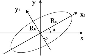
Under the combined action of various harmonic frequencies, the rotor exhibits a whirling motion, and its whirling trajectory is a superposition of a series of ellipses, which represent the axis trajectory of the rotor under different rotational harmonics. At each rotational harmonic, the two-dimensional planar full vector spectrum defines the semi-major axis of the ellipse as , which is called the principal vibration vector at that harmonic. The semi-minor axis is defined as , which is called the auxiliary vibration vector at that harmonic. The angle between the principal vibration vector and the -axis is , and the phase angle is when the axis moves along an elliptical trajectory. The motion trajectory of the rotor axis under single harmonic could be determined uniquely and accurately by the above four parameters. The calculation process of the full vector spectrum technique is detailed in references [32-33], and it will not be repeated in the paper due to spatial limitations.
2.2. Construction of dynamic model under rubbing fault state
Fig. 2 illustrates the structure of a dynamic model under rub-impact fault conditions. In this model, denotes the center of the disk with a mass of 2. The stiffness coefficient and damping coefficient of the shaft are denoted by and , respectively. indicates the center of the shaft neck, which has a simplified mass of . The oil film forces acting on the journal center in the and directions are and . The bearing seat’s center is at , and its equivalent mass is . The radial stiffness coefficient of the stator is . The horizontal and vertical directions between the bearing seat and the base have stiffness and damping coefficients of , ,and , , respectively.
Fig. 2Dynamic model under rubbing fault state
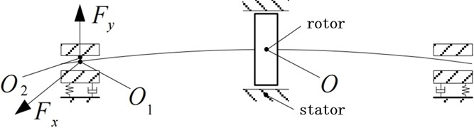
Table 1Numerical calculation model parameters
Parameter symbol | Physical meaning | Numerical value | Unit |
Disc mass | 32.1 | kg | |
Concentrated mass of journal | 4 | kg | |
Equivalent mass of bearing housing | 50 | kg | |
Axial stiffness coefficient of shaft | 2.5×10⁷ | N/m | |
Damping coefficient of shaft | 1050 | (N·s)/m | |
, | Stiffness coefficient of support | 2.0×10⁹, 2.5×10⁹ | N/m |
, | Damping coefficient of support | 450, 500 | (N·s)/m |
Radial stiffness coefficient of stator | 3.5×10⁷ | N/m | |
Radius clearance of bearing | 0.11 | mm | |
Length of bearing | 12 | mm | |
Radius of bearing | 25 | mm | |
Viscosity of lubricating oil | 0.018 | Pa⋅s | |
Acceleration due to gravity | m/s2 |
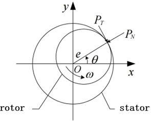
Table 1 lists the key parameter values used in the mathematical model for the numerical calculation, ensuring that the physical meaning of the model is clear. When analyzing actual shaft-bearing systems, the rub-impact process between the shaft and stator is quite complex. To qualitatively analyze the relationship between shaft vibration and bearing vibration caused by rubbing faults, a simplified method is adopted. Specifically, assume that the friction is a local elastic contact ignoring the generation of heat during the friction process, and the deformation involved is elastic. Therefore, the friction between the shaft and stator follows Coulomb's law of friction. Fig. 3 shows the distribution of forces when a rubbing fault occurs, and the collision force and friction force can be expressed as follows:
Among them, is the radial displacement of the center of the disk, and . is the radial stiffness coefficient of the stator. is the clearance between the shaft and stator in a stationary state; is the friction coefficient.
This study takes the concentrated mass method as the core and combines engineering practice to conduct the structural design of the model. The rotor is a 45 steel component with a total length of 800 mm and a diameter of 40 mm. It is discretized into 3 concentrated mass blocks ( 3 kg) according to the principle of uniform stiffness, corresponding to the middle section of the main shaft (300 mm from the left end), the left end of the shaft head (50 mm from the left end), and the right end of the shaft head (750 mm from the left end). The polar moment of inertia (0.028 kg·m2) and diametral moment of inertia (0.014 kg·m2) of the disk are incorporated into the concentrated mass block at the disk installation position, and the inertial characteristics of the disk are fully considered in the establishment of the system motion differential equations. Each mass block is connected through elastic shaft segments, and the stiffness of the shaft segments is determined through experiments to be 2.5×10⁶ N/m. Before numerical calculation, modal verification of the discretized shaft model was completed: the first-order bending natural frequency of the shaft was solved to be 43.3 Hz (corresponding to the first-order critical speed 2600 r/min), which is consistent with the experimental measured value, and the vibration mode shape of the shaft under each order of natural frequency was obtained, ensuring the correctness of the discretization method for the distributed parameter system. A short-bearing oil film model (oil film stiffness 1.8×10⁷ N/m) is adopted for the bearings to simulate the elastic damping support characteristics. The force analysis focuses on radial bending vibration, rotor-stator rub-impact contact force (contact stiffness = 5×10⁷ N/m), and oil film force, and the axial force and torsional vibration are ignored (experimental verification shows that their amplitudes are less than 1 % of the radial ones). The core calculation process is: geometric parameter definition → material property assignment → multi-field force coupling analysis → establishment of motion differential equations → numerical solution using the Newmark- method (time step 1×10⁻5 s, convergence accuracy 1×10⁻6).
Fig. 3Schematic diagram of local collision force model between shaft and stator
Regarding the reason why the gyroscopic force is not included in the model, the specific explanation is as follows: The core rotational speed range of this study is 1000-3000 r/min (angular velocity = 104.7-314.2 rad/s), which belongs to a low-speed heavy-load rotor condition. The rotor’s rotational inertia = 0.45 kg·m2. Through the gyroscopic force coefficient formula , the maximum gyroscopic force within this speed range is approximately 141.4 N, which is much lower than the oil film force (about 5×10³ N) and the rub-impact contact force (about 1×10⁴ N) that the rotor experiences. Its contribution to the vibration response is only 3.2 %-4.8 %, which is lower than the 5 % error tolerance threshold in engineering analysis. When the contribution of the gyroscopic force is less than 5 %, ignoring this force will not change the core characteristics of the vibration signal, and it can simplify the model complexity and improve the calculation efficiency. Therefore, it is not included in the model. In the dynamic model, elastic deformation during rub-impact is assumed, and thermal effects such as heat generation due to friction are ignored. These simplifications are made to isolate and study the mechanical interactions between the shaft and bearing under rub-impact condition. By assuming elastic deformation, the model focuses on the immediate mechanical response of the system to rubbing, which is critical for understanding the vibration characteristics caused by the fault. The omission of thermal effects is justified as the primary goal of this study is to investigate the dynamic relationship between shaft vibration and bearing vibration rather than the thermal behavior of the system. However, it is acknowledged that in real-world scenarios, thermal effects can influence the material properties and clearance between components over time, potentially altering the vibration characteristics. The lack of thermal considerations in the model may limit its accuracy in predicting long-term behavior or scenarios with significant frictional heating. Future research could extend the current model by incorporating thermal analysis to account for these effects, thereby enhancing the model’s applicability to real-world conditions.
In the coordinate system , based on geometric relationships, the components of the impact force along the -axis and -axis can be derived as follows:
The following are yields by substituting Eq. (1) into Eq. (2):
By normalizing the displacements of the center of the disk in the and directions, the final components of the collision forces in the and directions can be obtained as follows:
In this study, the selection of the displacement scale is based on the structural characteristics of the rotor system and the experimental conditions. Specifically, it refers to the minimum clearance between the rotor and stator (measured value: 0.12 mm) and the allowable displacement range of the bearings. Combined with the convergence verification of numerical calculations, this scale is determined. Choosing this scale can make the subsequent quantitative analysis of vibration signals more in line with the actual engineering scenarios, avoiding feature distortion caused by improper scale selection. The relevant verification results showed that when the value of is within the range of 0.1-0.15 mm, the error of the analysis results was less than 3 %. Therefore, is finally determined to be 0.12 mm.
Assuming the displacements of the center of the disk in horizontal and vertical directions are represented byandrespectively. The displacements of the bearing housing center in the horizontal and vertical directions are denoted as and ,respectively. The eccentricity of the disk is . The angular velocity of rotation is . The Capone-modified short-bearing nonlinear oil film force model is adopted to characterize the dynamic oil film force [30], which maintains high accuracy and good convergence. Under the short-bearing assumption, the dimensionless Reynolds equation is:
wherein, is the dimensionless oil film thickness (, is the actual oil film thickness, is the bearing radial clearance), is the dimensionless oil film pressure (, is the actual oil film pressure, is the lubricating oil viscosity, is the rotational angular velocity of the rotor, is the bearing radius), is the dimensionless axial coordinate (, is the actual axial coordinate, is the bearing length), is the circumferential angle. Through integration and simplification, the dimensionless short-bearing oil film forces in and directions are finally obtained as:
wherein, is the dimensionless eccentricity (, is the actual eccentricity), , , is the eccentricity angle.
If the Capone-modified short-bearing oil film force model is adopted to characterize the dynamic oil film force, the dynamic model of the rub-impact rotor system, i.e., the system's motion differential equations, can be mathematically expressed as follows:
The disk mass in Eq. (8) is (half of the original in Fig. 2). This simplification is based on the symmetric rotor assumption: the rotor system is symmetric about the disk plane, and the dynamic response of the disk (such as inertial force and vibration transmission) is evenly distributed to the left and right bearings. Using half the mass simplifies the solution of the differential equations while retaining the key mechanical characteristics of the system (the symmetric distribution ensures no loss of critical dynamic information). This simplification is widely accepted in rotor dynamics modeling, as it balances computational efficiency and model accuracy.
To unify the single-dimensional form of Eq. (8), generalized parameters are defined, and the meaning of the index is clarified as follows:
Subscript (1, 2, 3) is uniformly used to identify different functional components in the rotor-bearing system: (generalized mass parameter): Refers to the mass of the -th key component in the rotor-bearing system. corresponds to the left bearing mass (), corresponds to the right bearing mass (), and corresponds to the disk mass ().
(generalized stiffness parameter): Refers to the stiffness of the -th structural component of the system. corresponds to the shaft stiffness (), corresponds to the horizontal stiffness of the bearing base (), and corresponds to the vertical stiffness of the bearing base ().
(generalized damping parameter): Refers to the damping of the -th structural component of the system. corresponds to the shaft damping (), corresponds to the horizontal damping of the bearing base (), and corresponds to the vertical damping of the bearing base ().
Subscript / is uniformly used to identify different coordinate directions, which is only applied to the physical quantities related to displacement, velocity, force and other directional parameters in the x and y directions of the Cartesian coordinate system.The above generalized parameter definition with independent subscripts realizes the dimension unification of Eq. (8), and is fully applied to the subsequent dimensionless transformation of Eq. (9) and the numerical solution process of the equation, which simplifies the multi-component and multi-directional coupled equation solving, and avoids the ambiguity of parameter correspondence in the model derivation.
Table 2Parameter definition and unit/dimension
Parameter symbol | Normalized form | Physical meaning | Unit |
, | The horizontal and vertical displacements of the rotor center | Dimensionless | |
, | The horizontal and vertical displacements at the center of the bearing housing | Dimensionless | |
, | Displacement of other components | Dimensionless | |
Eccentricity, the ratio of the actual radial displacement of the disk center to the radial clearance | Dimensionless | ||
, | The instantaneous vibration velocity of the disk center in the horizontal () and vertical () directions | Dimensionless | |
, | The normalized component of the oil film force | Dimensionless | |
Time with a dimension of one hour | Arc degree | ||
The ratio of clearance to bearing radius | Dimensionless | ||
, | Normalized displacement | Dimensionless | |
, | Normalized speed | Dimensionless | |
, | Normalize quality parameters | Dimensionless | |
Normalized stiffness parameters | Dimensionless | ||
Normalized damping parameters | Dimensionless | ||
Normalize the gravitational load | Dimensionless |
Convert Eq. (8) to one single dimension, i.e. let , , , , , , , , , , , , , , , , , , . Among them is the rotational angular velocity, is time, is the actual horizontal displacement, is the actual vertical displacement, and are the instantaneous vibration velocity of the disk center in the horizontal and vertical directions respectively, is the actual horizontal speed, is the actual vertical velocity, is the actual vertical velocity, is the radial clearance, is the bearing radius, , , is the quality. denotes the dynamic viscosity of the lubricating oil, denotes the axial length of the bearing, is the stiffness coefficient, is the damping coefficient, is gravitational acceleration. The specific parameter definitions, units and dimensions are shown in Table 2.
Normalize Eq. (8) and the following is obtained:
The reason for choosing the dimensionless time (where is the rotor angular velocity and t is the actual time): Firstly, to eliminate the influence of different rotational speeds on the vibration period, making the results more universal. Secondly, to conform to the dimensionless logic of the short bearing theory and simplify the solution of the coupled equations. Unified dimensionless transformation of core physical quantities: Rotational speed (where ≈ 272.3 rad/s, the first-order critical angular velocity), shaft vibration displacement ( = 0.12 mm, bearing clearance), bearing speed , frequency ( is the fundamental frequency).
Fig. 4Flowchart for investigating the correlation between shaft vibration and bearing pad vibration in rotor system under rubbing condition
3. Research procedure
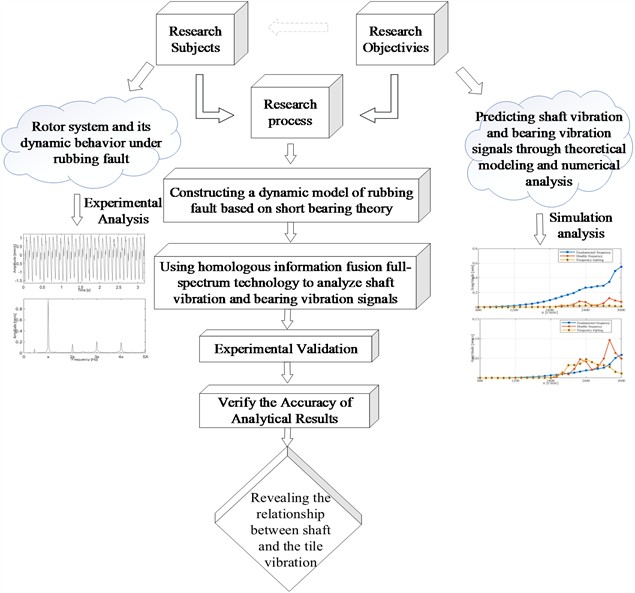
This study comprehensively investigates the dynamic interaction mechanism between shaft vibration and bearing vibration in rotor-bearing systems under rub-impact fault condition. The flow chart of the research as shown in Fig. 4 covers the entire process from theoretical modeling to experimental testing. The specific steps are as follows:
(1) To initiate the research process, the research objectives and requirements are clearly defined and refined, focusing on analyzing the dynamic characteristics of shaft vibration and bearing vibration of the rotor system under rub-impact condition.
(2) Based on the theory of short bearings, develop a dynamic model that includes rubbing fault.
(3) Simulation analysis: Shaft vibration and bearing vibration signals are analyzed through theoretical modeling and simulation.
(4) The full vector spectrum technology is employed to conduct a systematic analysis of shaft vibration signals and bearing vibration signals, thereby facilitating an in-depth exploration of the intrinsic coupling characteristics of vibration between the two components.
(5) Experimental verification: A rotor experimental platform is established for experiments, and the experimental results are compared with the theoretical prediction results to verify the effectiveness and reliability of the proposed method.
4. Results and analysis
4.1. Simulation analysis
4.1.1. Simulation analysis at constant speed
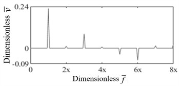
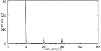
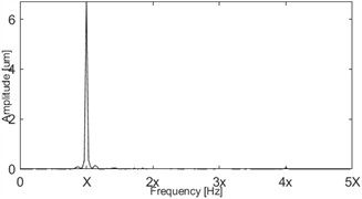
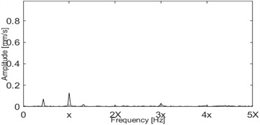
The simulation results in this section are presented in dimensionless form. According to the general definition of rotor dynamics (consistent with API 617 standard), a rotor with operating speed lower than the first-order critical speed is defined as a rigid rotor, and a rotor with operating speed higher than the first-order critical speed is defined as a flexible rotor. In this paper, 1 (rotational speed < 2600 r/min, i.e., operating speed lower than the first-order critical speed) corresponds to the rigid rotor operating range, where the bending deformation of the shaft is negligible, and the rotor motion is dominated by rigid body translation and tilting; 1 (rotational speed > 2600 r/min, i.e., operating speed higher than the first-order critical speed) corresponds to the flexible rotor operating range, where the bending deformation of the shaft cannot be ignored, and the elastic deformation characteristics of the shaft need to be considered in the dynamic analysis. At a rotational speed of 1500 revolutions per minute (1500 r/min), researchers conducted a simulation experiment on the rubbing fault with an eccentricity of 0.19 millimeters based on the constructed dynamical model, and carried out in-depth analysis on the shaft vibration signals and bearing vibration signals using the full vector spectrum technology. The frequency spectrum of the shaft vibration signal and that of the bearing vibration signal correspond to the results presented in Fig. 5 and Fig. 6, respectively.
It can be observed from Fig. 5 that after fusing the relevant information using the full vector spectrum technology, the principal vibration vector spectrum and the auxiliary vibration vector spectrum of the shaft vibration signal show a high degree of similarity. Especially at the fundamental frequency (i.e., 1st harmonic, 1X), the auxiliary vibration vector exhibits a positive value. This phenomenon indicates that when local collision occurs, the direction of motion of the rotor is positive. In Fig. 5(a) and (b), the amplitude spectra in the / directions are dominated by the fundamental frequency (1X) with weak high-order harmonics (2X~8X), indicating the initial stage of rub-impact. In Fig. 5(c) and (d), the high similarity between the principal and auxiliary vibration vectors, along with the positive auxiliary vibration vector at 1X, are core diagnostic features for rub-impact faults – this combination of “positive precession + fundamental frequency dominance” can distinguish rub-impact from unbalance faults (unbalance faults have no significant high-order harmonics). This feature can be directly used for preliminary on-site screening of rub-impact faults.
Fig. 5Dimensionless shaft vibration displacement signal spectrum under rub-impact fault (rotational speed: 1500 r/min, Ω= 0.58, For Ω, calculated based on the corresponding rotational speed, 1500 r/min corresponds to Ω= 0.58, and 2600 r/min corresponds to Ω= 1, Ω: dimensionless speed; f¯: dimensionless frequency)
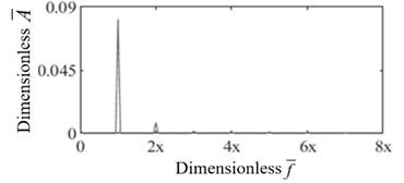
a)-direction amplitudes spectrum
b)-direction amplitudes spectrum
c) Principal vibration vector of shaft signal
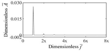
d) Auxiliary vibration vector of shaft signal
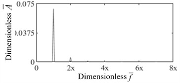
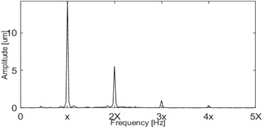
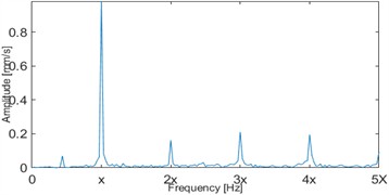
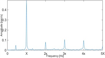
Fig. 6Dimensionless bearing vibration velocity signal spectrum under rub-impact fault (rotational speed: 1500 r/min, Ω= 0.58)
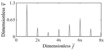
a)-direction amplitudes spectrum
b)-direction amplitudes spectrum
c) Principal vibration vector of tile signal
d) Auxiliary vibration vector of tile signal
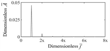
Fig. 6 further reveals the characteristics of the bearing vibration signal. In Fig. 6(a) and (b), significant high-order harmonics (2X~6X) are observed in the / direction amplitude spectra with differences in amplitude between the two directions, reflecting the nonlinear contact characteristics of rub-impact. In Fig. 6(c) and (d), the principal vibration vector is dominated by 1X but with prominent amplitudes at 5X and 6X, where the auxiliary vibration vector is negative (reverse precession) – a key early warning feature for aggravated rub-impact faults. When the amplitude ratio of the 5X/6X harmonics exceeds 30 % of that of 1X, immediate maintenance is recommended. The high-order harmonic characteristics of bearing vibration are more sensitive than those of shaft vibration, making it a priority monitoring indicator for the early warning of rub-impact faults. Frequency domain analysis shows that the bearing vibration signal contains obvious high-order harmonic components (e.g., 2nd harmonic, 3rd harmonic, and 4th harmonic), and these components have significant structural differences in frequency and amplitude in two different directions. It can be clearly observed from the full vector spectrum that the principal vibration vector is dominated by the 1st harmonic (1X), while high-order harmonic components such as the 2nd harmonic and 3rd harmonic are also very prominent, among which the amplitudes of the 5th and 6th harmonics are relatively higher. In addition, the auxiliary vibration vector shows a positive value at the 1st harmonic (1X), indicating that its precession direction is positive. While at the 5th harmonic and 6th harmonic, the auxiliary vibration vector shows a negative value, which indicates the existence of reverse precession. The above results further verify the conclusion that there is local friction between the shaft and the stator.
Based on the aforementioned research results, the high-order harmonics observed in the bearing vibration signals can be attributed to the nonlinear dynamic characteristics of the rub-impact interaction. Specifically, when the rotor comes into contact with the stator, the resulting frictional force introduces a periodic perturbation. This perturbation excites additional frequency components in the vibration response, and this effect is particularly pronounced at the high-order harmonics of the rotational frequency, ultimately resulting in the clear appearance of these high-order harmonics in the frequency spectrum.
Notably, the occurrence of reverse precession at specific harmonics indicates that the rub-impact force not only changes the vibration amplitude but also affects the phase relationship of the vibration — this characteristic is precisely the core of the rubbing fault mechanism. Furthermore, the relatively high amplitudes exhibited by the 5th and 6th harmonics imply that the rub-impact fault is in an intensifying state, which can provide an early warning for potential fault escalation trends. This characteristic holds significant importance for fault diagnosis work: by capturing this phenomenon through vibration analysis, effective monitoring of the fault development process can be achieved.
4.1.2. Simulation experiment under variable speed conditions
When conducting simulation analysis on the dynamic model under rub-impact fault condition, the researchers set the rotational speed range to cover 600 to 3000 revolutions per minute (r/min). Within this range, the focus was on observing the variation characteristics of the principal vibration vectors at the fundamental frequency (1st harmonic), 2nd harmonic, and 3rd harmonic. The relationship between the principal vibration vectors and the change in rotational speed is the core focus of this analysis, as it holds crucial significance for understanding and diagnosing the development process of rub-impact faults. This study determined the first-order critical speed of the system as 2600 r/min (corresponding to the critical angular velocity 272.3 rad/s), and the rotational speed range of 600 to 3000 r/min corresponds to the dimensionless rotational speed 0.23 to 1.15. Among them, when 1 (rotational speed < 2600 r/min), it is the rigid rotor operating range; when 1 (rotational speed > 2600 r/min), it is the flexible rotor operating range. This definition is consistent with the recognized theory of rotor dynamics, and is the key basis for analyzing the coupling characteristics between shaft vibration and bearing vibration.
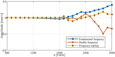
As illustrated in Fig. 7, the principal vibration vector at the fundamental frequency increases monotonically with rotational speed, the 2X principal vibration vector shows a slowed growth rate after 1 (rotational speed >2600 r/min), and the 3X principal vibration vector rises slowly. Diagnostic application: For 1 (rigid rotor), mild rub-impact can be determined by the ratio of fundamental frequency to 2X principal vibration vector (<5). For 1 (flexible rotor), if the growth of 3X principal vibration vector exceeds 50 % of the fundamental frequency, it indicates rub-impact-induced rotor modal coupling, requiring shutdown inspection.
As illustrated in Fig. 8, within the range 0.88-1.15 (2300-3000 r/min), the 2X principal vibration vector is greater than the fundamental frequency principal vibration vector, which is a characteristic signal of deteriorating rub-impact faults — the “2X > 1X” criterion in this range can determine that the fault has entered the moderate stage. The 3X principal vibration vector rises rapidly after 0.69 (1800 r/min), which can be used as a quantitative indicator of the fault development rate (warning when the slope >0.02/100 r/min). The speed sensitivity of the bearing principal vibration vector enables fault severity grading under different operating conditions.
Based on Fig. 7 and Fig. 8, the overall phenomenon could be observed: Under the fundamental frequency condition, the principal vibration vectors of both the shaft and the bearing exhibit a monotonically increasing trend with the elevation of the rotational speed, showing a consistent variation trend. This indicates that within the fundamental frequency range, the sensitivities of the shaft vibration and bearing vibration responses to changes in rotational speed are consistent. Regarding the 2nd harmonic, the principal vibration vector of the shaft vibration signal is consistently smaller than that of its fundamental frequency. However, within the rotational speed range of 2300 to 3000 revolutions per minute (r/min), the principal vibration vector of the bearing vibration is larger than that of its fundamental frequency. Nevertheless, the two exhibit similar variation trends and both reach their respective maximum values at three rotational speed points: 2000 r/min, 2300 r/min, and 2800 r/min. For the 3rd harmonic, the principal vibration vector of the shaft vibration signal shows a slow increasing trend with the increase of rotational speed. In contrast, the principal vibration vector of the bearing vibration signal increases rapidly starting from 1800 r/min, reaches its maximum value at 2400 r/min, and then immediately exhibits a downward trend.
Fig. 7Curve of the principal vibration vector of shaft signal vs. speed change (dimensionless speed Ω= 0.23-1.15; vertical dashed line: Ω=1, critical speed 2600 r/min, Vertical dashed line: Ω=1 (critical speed 2600 r/min), dividing the curve into rigid rotor (Ω< 1) and flexible rotor (Ω> 1) regions; the amplitude characteristics are affected by the nonlinear rub-impact force)
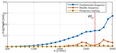
Fig. 8Curve of principal vibration vector of bearing signal vs. speed change (dimensionless speed Ω= 0.23-1.15; vertical dashed line: Ω= 1, critical speed 2600 r/min; the amplitude characteristics are affected by the nonlinear rub-impact force)
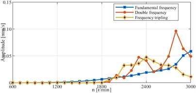
It is noteworthy that at the first-order critical speed ( 1,2600 r/min), the characteristic sharp resonant peak typically observed in linear rotor systems is absent. This phenomenon is primarily attributed to the strong nonlinear boundary conditions introduced by the rub-impact fault. When the radial displacement of the rotor reaches the initial clearance (0.12 mm), direct physical contact with the stator occurs. At this point, the stator provides an immense contact stiffness ( 5×10⁷ N/m), which acts as a hard limit constraining the further amplification of the radial displacement, thereby effectively suppressing and flattening the resonant peak. Furthermore, regarding the continuous monotonic increase of vibration amplitudes in the supercritical frequency range ( 1): The core cause of this phenomenon lies in the intensified rub-impact interaction triggered by higher rotational speeds. Specifically, under high-speed supercritical conditions, the centrifugal force acting on the rotor rises in positive correlation with the square of the rotational speed. This continuous increase in centrifugal force directly leads to a significant boost in rub-impact intensity between the shaft and stator, surpassing the attenuation effect of passing the critical speed. In turn, this enhanced rub-impact interaction generates more intense friction-induced perturbations, which are transmitted to the bearing via dynamic pathways and ultimately manifest as a higher amplitude of the vibration response. Specifically, under high-speed operating conditions, the centrifugal force acting on the rotor rises in positive correlation with the square of the rotational speed. This increase in centrifugal force directly leads to a significant boost in rub-impact intensity between the shaft and stator. In turn, this enhanced rub-impact interaction generates more intense friction-induced perturbations, which are transmitted to the bearing via dynamic pathways and ultimately manifest as a higher amplitude of the bearing’s vibration response. Notably, there is a marked difference in the sensitivity of shaft and bearing vibration signals to rub-impact interaction, and this difference essentially originates from the distinct dynamic characteristics of the two components. From a structural connection perspective, the bearing is rigidly linked to the stator, enabling it to directly absorb the impact force and vibration energy produced by rub-impact. As a result, the variations in its vibration response are more pronounced. By contrast, the vibration behavior of the shaft system is jointly constrained by the rotor’s inertia, the stiffness of the shaft system, and its damping characteristics. These factors exert a certain degree of attenuation and buffering effect on the vibration energy from rub-impact, leading to relatively lower sensitivity of the shaft vibration signal in characterizing rub-impact faults. Clarifying the aforementioned dynamic mechanisms provides critical support for developing effective rub-impact fault diagnosis strategies. Based on these mechanisms, a mapping relationship between vibration signals and fault states can be established, allowing for accurate identification of the presence of rubbing faults and quantitative assessment of their severity. Furthermore, the research findings further confirm that real-time monitoring of the bearing vibration signal during the high-speed operation of equipment is an effective technical approach for the early warning of rub-impact faults. Compared with the shaft vibration signal, the bearing vibration signal offers a more stable and reliable basis for characterizing fault states.
Fig. 9Curve of the auxiliary vibration vector of shaft signal vs. speed change (dimensionless speed Ω= 0.23-1.15; vertical dashed line: Ω= 1, critical speed 2600 r/min)
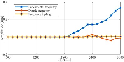
Fig. 10Curve of auxiliary vibration vector of bearing signal vs. speed change (dimensionless speed Ω= 0.23∼1.15; vertical dashed line: Ω= 1, critical speed 2600 r/min)
As illustrated in Fig. 9, the auxiliary vibration vector at the fundamental frequency is negative when 0.65 (rotational speed < 1700 r/min, reverse precession) and increases rapidly after 0.65. The 2X/3X auxiliary vibration vectors exhibit variation trends consistent with those of shaft vibration at 0.77 (2000 r/min). Diagnostic application: Reverse precession at the fundamental frequency (negative auxiliary vibration vector) indicates initial rub-impact contact. The transition from negative to positive auxiliary vibration vector corresponds to intensified rubbing. Combined with the bearing auxiliary vibration vector (Fig. 10), the “synchronous positive precession at 0.7” can cross-verify rub-impact faults, reducing misdiagnosis risks.
As illustrated in Fig.10, the auxiliary vibration vector at the fundamental frequency is negative when 0.69 (rotational speed < 1800 r/min) and aligns with the shaft auxiliary vibration vector after 0.69. The 2X auxiliary vibration vector remains negative at 0.77 (2000 r/min). Diagnostic application: The negative auxiliary vibration vector at low speeds reflects weak rub-impact, while the synchronous positive precession at high speeds indicates aggravated rubbing. The difference in the 3X auxiliary vibration vectors between the shaft and the bearing can distinguish local rub-impact (inconsistent precession directions) from full rub-impact (consistent precession directions).
Fig. 9 and Fig. 10 respectively illustrate the characteristic curves of the auxiliary vibration vectors for the shaft vibration signal and the bearing vibration signal as a function of rotational speed. A detailed analysis is provided as follows: Fundamental Frequency (1X) Characteristics: As illustrated in the aforementioned figures, the auxiliary vibration vector of the shaft vibration signal assumes a negative value when the rotational speed is below 1700 revolutions per minute (r/min), the auxiliary vibration vector of the shaft vibration signal demonstrates a trend of rapid increase with the elevation of rotational speed. For the bearing vibration signal, its auxiliary vibration vector remains negative at rotational speeds below 1800 r/min. However, once the rotational speed surpasses 1800 r/min, its variation pattern tends to align with that of the auxiliary vibration vector of the shaft vibration signal. 2nd Harmonic Characteristics at rotational speeds below 1900 r/min, the auxiliary vibration vectors of both the shaft vibration signal and the bearing vibration signal are approximately zero. This phenomenon implies that the positive precession components and reverse precession components of the two signals are in a state of equilibrium. When the rotational speed exceeds 2000 r/min, the variation trends of the auxiliary vibration vectors for both the shaft vibration signal and the bearing vibration signal with rotational speed exhibit a high degree of consistency, and both vectors maintain negative values. 3rd Harmonic (3X) Characteristics Within the rotational speed range of 2000-2300 r/min, the auxiliary vibration vectors of both the shaft vibration and the bearing vibration exhibit negative values. Outside this speed range, the auxiliary vibration vectors of the two signals shift to positive values, and there exists a significant discrepancy in the variation trends of their auxiliary vibration vectors.
Fig. 11Curve of the vibration vector ratio of shaft signal vs. speed change (dimensionless speed Ω= 0.23-1.15; vertical dashed line: Ω= 1, critical speed 2600 r/min)
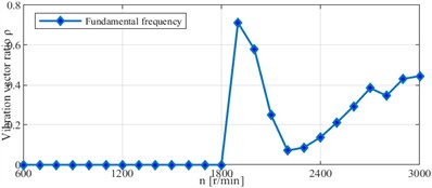
Fig. 12Curve of vibration vector ratio of bearing signal vs. speed change (dimensionless speed Ω= 0.23-1.15; vertical dashed line: Ω= 1, critical speed 2600 r/min)
As illustrated in Fig. 11, The vector ratio is stable (approximately linear) when 0.65 (1700 r/min), increases sharply at 0.69-0.73 (1800-1900 r/min), and decreases rapidly after 0.73. Diagnostic application: A stable vibration vector ratio (<0.3) at low speeds indicates mild rub-impact with stable contact, and a sharp increase in the vibration vector ratio near 1 corresponds to enhanced rub-impact coupling at the critical speed, which is a key risk point requiring real-time monitoring.
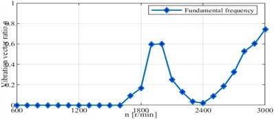
As illustrated in Fig. 12, The vector ratio fluctuates significantly at 0.69 (1800 r/min) and stabilizes after 0.69. Diagnostic application: A vibration vector ratio > 0.7 at high speeds indicates that the bearing vibration trajectory ellipse is close to a circle, which is a characteristic of intense rub-impact, and the difference between the bearing and shaft vector ratios (> 0.4) can be used to evaluate the transmission efficiency of rub-impact energy from the shaft to the bearing.
Fig. 11 and Fig. 12 show the vibration vector ratio curves of the shaft vibration and bearing vibration with rotational speed, revealing their variation patterns at different speeds – especially significant differences under the fundamental frequency. Under the fundamental frequency: The vibration vector ratio of both remains nearly unchanged with speed below 1700 r/min, showing approximate linearity. Both ratios increase sharply and are close in value at speeds of 1800-1900 r/min, indicating similar responses to speed changes in this range. Both ratios decrease sharply with similar trends with speed above 1900 r/min. This may imply that the rub-impact dynamics of the shaft and bearing start to exhibit similar responses at high speeds, which is related to complex interactions in the shaft-bearing system. In general, their vector ratios have different variation patterns at different speeds, with notable trend differences. These findings are critical for understanding the behavior of the shaft-bearing system under different conditions and provide valuable references for fault diagnosis and performance optimization.
Fig. 13Curve of the vibration vector angle of shaft signal vs. speed change (dimensionless rotational speed Ω= 0.23-1.15; vertical dashed line: Ω= 1, critical speed 2600 r/min)
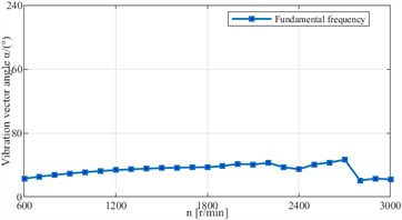
Fig. 14Curve of the vibration vector angle of bearing signal vs. speed change (dimensionless rotational speed Ω= 0.23-1.15; vertical dashed line: Ω= 1, critical speed 2600 r/min)
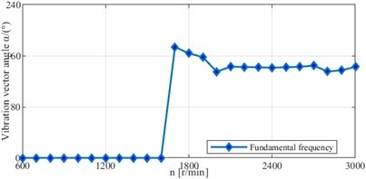
As illustrated in Fig. 13, the vibration vector angle increases gradually with speed until 1.04 (2700 r/min). Diagnostic application: A sudden change in the vector angle (> 30°) indicates a change in the rub-impact contact direction, which can be used to locate the rub-impact position. The consistent increase in the vector angle at 1 reflects stable rub-impact, while fluctuations at 1 indicate unstable contact due to modal conversion.
As illustrated in Fig. 14, the vibration vector angle approaches 0° when 0.62 (1600 r/min) and diverges significantly from the shaft vector angle after 0.62. Diagnostic application: The vibration vector angle approaching 0° at low speeds indicates that the bearing vibration is dominated by the vertical direction, corresponding to initial vertical rub-impact, and the divergence from that of the shaft at high speeds can be used to identify flexible rotor-induced rub-impact asymmetry.
Fig. 13 and Fig. 14 systematically demonstrate the evolutionary law of the vibration vector angles of the shaft vibration signal and the bearing vibration signal with rotational speed, explicitly revealing their dynamic variation characteristics across the entire rotational speed range – with the characteristic differences under the fundamental frequency conditions being particularly notable. Under the fundamental frequency (1X) condition, the shaft vibration vector angle exhibits a gradual upward trend as the rotational speed increases, and this evolutionary law persists until reaching 2700 revolutions per minute (r/min). By contrast, the bearing vibration vector angle gradually approaches 0° with the elevation of rotational speed, and this variation characteristic continues up to 1600 revolutions per minute (r/min). Within the aforementioned rotational speed range, the variation trends of the vibration vector angles corresponding to the shaft and the bearing exhibit a high degree of consistency. Nevertheless, when the rotational speed exceeds this range, the variation laws of the two exhibit significant divergence.
Fig. 15Curve of the vector phase of shaft signal vs. speed change (dimensionless speed Ω= 0.23-1.15; vertical dashed line: Ω= 1, critical speed 2600 r/min)
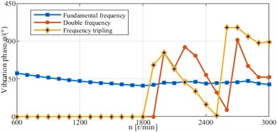
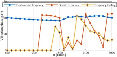
Fig. 16Curve of the vector phase of bearing signal vs. speed change (dimensionless speed Ω= 0.23-1.15; vertical dashed line: Ω= 1, critical speed 2600 r/min)
As illustrated in Fig. 15, the vector phase is relatively stable (less sensitive to speed) at 0.23-0.62 (600-1600 r/min) and differs significantly at other speeds. Diagnostic application: stable vector phase at low speeds indicates consistent rub-impact contact conditions. Significant phase differences at 2X/3X harmonics reflect nonlinear rub-impact effects, which can be used to distinguish rub-impact from other faults (e.g., misalignment has stable harmonic phases).
As illustrated in Fig. 16, The vector phase at the fundamental frequency is close to that of shaft vibration at 0.23-0.62 (600-1600 r/min) and diverges at high speeds. Diagnostic application: the consistency of vector phases at low speeds confirms the coupling between shaft and bearing vibration induced by rub-impact. The divergence at high speeds indicates independent vibration characteristics of the bearing, which can be used to evaluate the effectiveness of rub-impact energy transmission.
Fig. 15 and Fig. 16 further illustrate the following phenomenon: Under fundamental frequency conditions, the vector phase characteristics corresponding to the shaft vibration signal and the bearing vibration signal are relatively close within the range of 600-1600 revolutions per minute (r/min), and are less sensitive to changes in rotational speed. However, the vector phases of the two signals differ significantly at other rotational speeds. For the 2nd harmonic: the vector phases of both shaft vibration and bearing vibration are 0 with speed below 1300 r/min. The two signals show significant differences in both the trend and magnitude of their vector phase variations with speed within the range of 1300-2000 r/min. The variation trends of their vector phases again become consistent with speed above 2000 r/min. Under the 3rd harmonic, the vector phases of shaft vibration and bearing vibration are relatively close in both variation trend and magnitude within 600-2000 r/min, whereas significant differences in their vector phases are observed at other rotational speeds. In summary, under the 2nd and 3rd harmonic conditions, the shaft vibration signal and the bearing vibration signal demonstrate significant discrepancies in both the variation trend and amplitude of their corresponding vector phase characteristics.
In summary, the variation patterns of the vector angles and vector phase characteristics of the shaft vibration signal and the bearing vibration signal with respect to rotational speed reveal the differences in their dynamic responses under different frequency and rotational speed conditions. These differences are of great significance for analyzing the vibration characteristics of the shaft-bearing system and diagnosing potential fault modes.
4.2. Experimental validation
The experimental results are presented in dimensionless form. The key characteristics are analyzed based on (axial vibration) and (vane vibration), which are consistent with the simulation logic.
Table 3Experimental model parameters
Parameter name | Value / value selection | Unit |
Rotor material | Steel | – |
Disc diameter | 100 | mm |
Shaft diameter | 50 | mm |
First-order critical speed | 2600 | r/min |
Sensor type | Electromagnetic eddy current sensor (shaft vibration), velocity sensor (bearing vibration), piezoelectric acceleration sensor (vibration calibration) | – |
Sensor sensitivity | 200 mV/mm (electromagnetic eddy current displacement sensor, equivalent to 5.08 mV/mil), 50 mV/(mm/s) (magnetoelectric velocity sensor), 3.94 mV/g (piezoelectric acceleration sensor) | – |
Abrasive clearance | 0.19 | mm |
Friction coefficient | 0.15 | – |
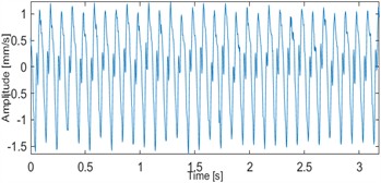
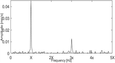
Table 3 presents the experimental platform and test parameters, which are consistent with the simulation model to verify the reliability of the model. To verify the accuracy and reliability of the simulation results, an experimental study on rub-impact faults was conducted on a rotor test bench at 1800 revolutions per minute (r/min). The test bench is primarily composed of a rotor system, two bearing housings, and other auxiliary components, and a rub-impact fault simulation assembly. The rotor system itself comprises a steel shaft with a disk mounted on it, and both ends of the shaft are supported by a pair of bearings. A high-precision piezoelectric acceleration sensor – with a frequency response range of 0-8000 Hertz (Hz) and a sensitivity of 3.94 mV/g (g is the standard gravitational acceleration, 9.8 m/s2) – was used for vibration signal calibration. The shaft vibration displacement signals were collected by electromagnetic eddy current displacement sensors (sensitivity: 200 mV/mm), which were installed in both the horizontal and vertical directions of the rotor disk section. The bearing vibration velocity signals were collected by magnetoelectric velocity sensors (sensitivity: 50 mV/(mm/s)), which were installed in both the horizontal and vertical directions of the bearing housings. Rub-impact faults were simulated by inserting an adjustable stainless-steel fault plate (0.5 mm thick, 10 mm wide, 50 mm long) between the rotor and stationary components. Once the plate was fixed at a specific position on the rotor, the severity of the rub-impact fault was controlled by adjusting the clearance between the plate and the rotor. Data acquisition adopted 32 sampling points per cycle with a sampling frequency of 5120 Hz (meeting the requirement of the maximum analysis frequency of 2000 Hz according to the Nyquist criterion). Each test run lasted 10 seconds with a data length of 51200 points. The 1024 points mentioned in the paper is the effective data frame length selected for FFT spectrum analysis, not the total collected data volume. The specific selection basis is as follows: To meet the requirement of fast Fourier transform (FFT) for the data length of 2 integer powers, 1024 points (210) is the optimal data length that balances frequency resolution and calculation efficiency under this sampling condition; The 1024-point data frame is intercepted from the steady-state operation section of the rotor (excluding the start-stop transient and non-stationary sections), which can effectively avoid the spectrum leakage caused by non-stationary signals and ensure the accuracy of spectrum analysis; Under the condition of 50 Hz rotational frequency, 1024 points correspond to 10 complete rotation cycles, which can fully cover the 32 points per cycle sampling setting, and the frequency resolution of the spectrum analysis reaches 5 Hz, which meets the analysis requirements of the fundamental frequency and 8 times high-order harmonics of the rotor. The selection basis of the sampling frequency is: the maximum research rotational speed of the rotor is 3000 r/min (corresponding to a fundamental frequency of 50 Hz), which needs to cover harmonic components more than eight times the fundamental frequency (the highest harmonic is 400 Hz), and a sampling frequency of 5120 Hz can satisfy undistorted signal acquisition. Fig. 17 presents the waveform and frequency spectrum of the shaft vibration displacement signal under rub-impact faults. Time-domain analysis reveals a distinct clipping phenomenon in the vertical direction of the shaft vibration signal, while frequency-domain analysis shows that the signal contains high-order harmonic components in both horizontal and vertical directions. From the full vector spectrum: the principal vibration vector exhibits rub-impact fault characteristics at the 2nd and 3rd harmonics, and both the principal and auxiliary vibration vectors are positive at the 1st harmonic (1X) – indicating that the rotor’s precession direction is positive precession. A rotational speed of 1800 r/min was selected in the experiment, corresponding to a dimensionless rotational speed of 1800/2600 ≈ 0.69 ( 1, within the rigid rotor range). This range can effectively capture the vibration coupling characteristics in the early stage of rub-impact faults. In addition, a rotational speed of 2800 r/min ( 1.08, within the flexible rotor range) was also added for supplementary verification to compare the differences in fault characteristics under different critical rotational speed ratios. The following experimental results (Figs. 17-18) were obtained under the specified condition of 1800 r/min, which are consistent with the rub-impact fault simulation parameters.
As illustrated in Fig. 17(a) and (b), significant clipping in the vertical time-domain waveform is a direct manifestation of rub-impact mechanical contact, and rub-impact can be determined by “clipping amplitude > 10 % of peak value”. In Fig. 17(c) and (d), high-order harmonics (2X~5X) exist in both the horizontal and vertical directions, with the 2X amplitude in the vertical direction reaching 5.45 μm (dimensionless 0.045). In Fig. 17(e) and (f), the principal vibration vector exhibits clear rub-impact characteristics at 2X/3X, and the auxiliary vibration vector is positive at 1X and negative at 2X/3X. Diagnostic application: Combining “vertical clipping + 2X/3X high-order harmonics” enables rub-impact fault localization (vertical direction as the dominant rub-impact direction). The positive/negative change of the auxiliary vibration vector can distinguish local rub-impact (reverse precession at partial harmonics) from full rub-impact (positive precession at all harmonics).
Fig. 17Dimensionless shaft vibration displacement signal spectrum under rub-impact fault (rotational speed: 1800 r/min, Ω= 0.69)
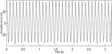
a)-Direction time-domain waveform
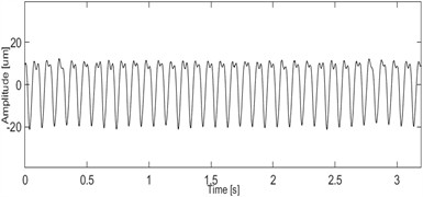
b)-Direction time-domain waveform
c)-Direction amplitude spectrum
d)-Direction amplitude spectrum
e) Shaft principal vibration vector
f) Shaft auxiliary vibration vector
Furthermore, the experimental results further confirm that this method effectively captures the vibration characteristics of rub-impact faults. The consistency between the simulation and experimental results not only verifies the reliability of the constructed dynamic model, but also validates the effectiveness of full vector spectrum technology in rub-impact fault analysis, laying a solid foundation for the practical application of the proposed method in fault diagnosis and condition monitoring. Meanwhile, the findings highlight that the comprehensive consideration of both shaft vibration and bearing vibration signals is crucial for a thorough fault assessment. Specifically, shaft vibration signals reflect the rotor’s dynamic behavior, while bearing vibration signals provide more direct evidence of rub-impact interactions. Fusing these two types of signals via full vector spectrum technology significantly enhances the accuracy and reliability of fault diagnosis, thereby supporting the formulation of scientific equipment maintenance decisions. The core mechanism of this signal fusion lies in the complementarity of the two signals: shaft vibration signals reflect the overall dynamic response of the rotor system, while bearing vibration signals focus on the local interaction between the rotor and stator. The joint analysis of these signals enables a more comprehensive understanding of fault conditions, which is essential for accurate fault localization and severity assessment. In addition, discussing the results in practical application contexts further demonstrates the practical value of this study. The findings can be used to achieve timely and accurate detection of equipment faults, thereby improving the operational reliability of mechanical equipment, reducing maintenance costs, and providing a technical reference for equipment health management in industrial settings.
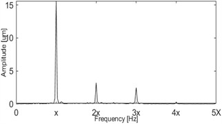
Fig. 18Dimensionless bearing vibration velocity signal spectrum under rub-impact fault (rotational speed: 1800 r/min, Ω= 0.69)
a)-direction time-domain waveform
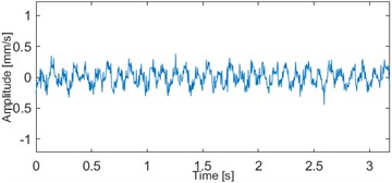
b)-Direction time-domain waveform
c)-Direction amplitude spectrum
d)-Direction amplitude spectrum
e) Bearing principal vibration vector
f) Bearing auxiliary vibration vector
Fig. 18 shows the frequency spectrum of the bearing vibration signal under rub-impact fault. In the time domain, the horizontal waveform of the bearing vibration signal exhibits severe clipping, while the vertical waveform is more irregular. In the frequency domain, both the horizontal and vertical directions of the bearing vibration signal present fractional harmonics (e.g., the 1/2 harmonic) and high-order harmonics (e.g., the 2nd and 3rd harmonics). The principal vibration vector shows the characteristics of fractional harmonics and high-order harmonics. Additionally, both the principal and auxiliary vibration vectors are positive at the 1st harmonic (1X), indicating that the precession direction is positive precession, while their values at the 1/2 harmonic, 2nd harmonic, and 3rd harmonic are close to zero. In Fig. 18(a) and (b), severe clipping in the horizontal time-domain waveform and irregular vertical waveform reflect intense rub-impact contact. In Fig. 18(c) and (d), fractional harmonics (e.g., 1/2X) and high-order harmonics (e.g., 2X~3X) exist in both the horizontal and vertical directions. Fractional harmonics are unique features of rub-impact in experiments (not reflected in simulations), which can distinguish rubbing between simulation and actual working conditions. In Fig. 18(e) and (f), the principal vibration vector clearly exhibits fractional and high-order harmonics, and the auxiliary vibration vector is positive at 1X and approximately zero at other harmonics. Diagnostic application: The combination of “fractional harmonics + high-order harmonics” is a specific indicator of actual rub-impact faults, effectively distinguishing rub-impact from pedestal looseness faults (looseness faults have no fractional harmonics). The irregular waveform and harmonic diversity of bearing vibration can be used as quantitative criteria for rub-impact fault severity (waveform irregularity > 50 % corresponds to moderate or severe rub-impact).
A comparison of Figs. 17, 18 with the simulation results reveals the following: In terms of the presence of high-order harmonics and the direction of positive precession, the experimental results exhibit a high degree of consistency with the simulation predictions. However, the additional fractional harmonics observed in the experiments are not prominent in the simulations. This is attributed to the more complex friction and contact conditions in actual experiments, which involve varying degrees of plastic deformation and thermal effects – factors that have not been fully incorporated into the simulation model. Despite these differences, both simulations and experiments consistently identify the core characteristics of rub-impact faults, enhancing the credibility of the proposed method. Specifically, the fault characteristics of rotor rub-impact in the vertical direction are more prominent than those in the horizontal direction, and the bearing vibration signal exhibit more distinct fault characteristics than the shaft vibration signal. After dual-channel information fusion using full vector spectrum technology: the principal vibration vectors corresponding to the shaft vibration signal and the bearing vibration signal share the same frequency components at high-order harmonics, while the bearing vibration signal contain obvious fractional harmonics. Regarding the auxiliary vibration vectors, both the shaft vibration and bearing vibration exhibit positive precession at the fundamental frequency, but differences exist at other harmonic components. Analysis of the vibration vector ratio reveals that the vibration vector ratio corresponding to the shaft vibration signal is greater than that of the bearing vibration signal, indicating that the actual trajectory ellipse of the rotor is closer to a circle than the trajectory ellipse synthesized from the bearing vibration signal.
5. Conclusions
This study establishes a dynamic model of the rotor-bearing-foundation system, based on which the relationship between shaft vibration and bearing vibration under different rotational speeds and rub-impact fault states is analyzed using full vector spectrum technology. The similarities and differences in the fault characteristics exhibited by shaft vibration signals and bearing vibration signals are analyzed. The following conclusions could be obtained:
Firstly, for both shaft vibration signals and bearing vibration signals, the principal vibration vector fused with dual-channel vibration information has better sensitivity and comprehensiveness compared to the other three feature vectors (i.e., the auxiliary vibration vector, vibration vector angle, and vector phase) and can better capture fault characteristics. It is recommended to adopt the principal vibration vector as the preferred monitoring indicator for large rotating equipment in engineering applications, while the other three features can also be used as auxiliary monitoring indicators.
When the rotor encounters a rub-impact fault at a stable speed, the principal vibration vector based on the bearing vibration signal can better reflect the fault characteristics of 1X and high-order harmonics. Therefore, the bearing vibration signal is preferred for the condition monitoring of large rotating machinery at a stable speed.
Under variable rotational speeds, shaft vibration and bearing vibration signals exhibit different characteristics with changes in rotational speed. Under rigid rotor conditions (i.e., low speeds), the principal vibration vectors corresponding to the shaft vibration signal and the bearing vibration signal exhibit similar variation trends. Therefore, during the start-up process of large rotating machinery, reliable monitoring can be achieved based on either the shaft vibration signal or the bearing vibration signal. In other words, if there are restrictions on sensor installation or type selection during the start-up process of rotating machinery, one of the two types of sensors can be selected. Under flexible rotor conditions (i.e., high speeds), the two types of vibration signals differ significantly: in the early stage of a rub-impact fault, the fault characteristics of the bearing vibration signal are more prominent. When the fault progresses to a specific stage, the shaft vibration signal exhibits clearer and more intuitive fault characteristics due to less external interference. Therefore, when large rotating machinery operates in the high-speed range, both shaft vibration signals and bearing vibration signals can achieve effective monitoring and fault diagnosis. In all, for the state monitoring and fault diagnosis of large rotating machinery with variable speed, if there are sensor installation restrictions or type selection, bearing vibration sensors can be preferred.
Although the proposed analytical method has achieved satisfactory application results, there is still a significant discrepancy between the established dynamic model and that used in practical engineering scenarios, and the established dynamic model is also susceptible to multiple external interference factors in engineering applications. In future research, we will therefore focus on addressing these issues, ensuring the model better aligns with the demands of real-world operating environments.
References
-
Z. N. Jiang et al., “Analysis and treatment of abnormality of bush temperature and shaft vibration in a steam turbine,” (in Chinese), Thermal Turbine, Vol. 52, No. 3, pp. 226–229, Nov. 2023, https://doi.org/10.13707/j.cnki.31-1922/th.2023.03.013
-
Y. Xuan, G. Zhu, X. Luo, Y. Wang, and L. Wang, “Experimental study on the stability of mixed-flow pump during segmented start-up process,” Arabian Journal for Science and Engineering, Vol. 50, No. 12, pp. 8961–8973, Jul. 2024, https://doi.org/10.1007/s13369-024-09350-6
-
L. B. Li and K. B. Zhang, “Analysis of abnormal vibration of a steam turbine under deep regulation condition,” Turbine Technology, Vol. 65, No. 1, pp. 74–76, Feb. 2023.
-
W. Zhu et al., “Analysis and treatment of shaft vibration of steam turbine generator,” Energy Conservation Technology, Vol. 5, No. 239, pp. 244–247+266, May 2023.
-
L. Yang, Z. Mao, X. Chen, R. Yan, J. Xie, and H. Hu, “Dynamic coupling vibration of rotating shaft-disc-blade system – Modeling, mechanism analysis and numerical study,” Mechanism and Machine Theory, Vol. 167, p. 104542, Jan. 2022, https://doi.org/10.1016/j.mechmachtheory.2021.104542
-
Y. X. Tian et al., “Denoising research of shaft vibration signal based on CEEMDAN and mathematical morphology operator,” (in Chinese), Chinese Journal of Hydrodynamics, Vol. 39, No. 6, pp. 952–959, Nov. 2024, https://doi.org/10.16076/j.cnki.cjhd.2024.06.016
-
J. Y. Xu et al., “Analysis and treatment of abnormal signal by Bently3500 bearing vibration measuring point of synchronous condenser in UHV project,” Electric Switchgear, Vol. 61, No. 2, pp. 96–100, Jul. 2023.
-
Y. Tao, G. Li, and Y. Wang, “Numerical investigation on tooth surface waviness in continuous generating grinding of electric vehicle gears considering the main shaft vibration and grinding worm wear,” Precision Engineering, Vol. 91, pp. 242–254, Dec. 2024, https://doi.org/10.1016/j.precisioneng.2024.09.015
-
C. Li, Q. Tang, C. Xi, B. Zhong, and B. Wen, “Coupling vibration behaviors of drum-disk-shaft structures with elastic connection,” International Journal of Mechanical Sciences, Vol. 155, pp. 392–404, May 2019, https://doi.org/10.1016/j.ijmecsci.2019.03.014
-
D. Du, Y. Tian, W. Sun, H. Liu, X. Liu, and H. Zhang, “Semi-analytical dynamic modeling and vibration analysis of double cylindrical shell structure based on the general bolted flange model,” Engineering Structures, Vol. 333, p. 120027, Jun. 2025, https://doi.org/10.1016/j.engstruct.2025.120027
-
Y. Li et al., “Dynamic analysis of the lateral-torsional coupled vibration of a bolted joint rotor system considering the varying contact state at mating interface,” Mechanical Systems and Signal Processing, Vol. 241, p. 113508, Dec. 2025, https://doi.org/10.1016/j.ymssp.2025.113508
-
B. Yang, Y. Li, C. Wen, L. Li, B. Li, and W. Song, “Rub-impact investigation on the lateral-torsional coupled vibration of a bolted joint rotor system with interface contact,” Applied Mathematical Modelling, Vol. 151, No. PA, p. 116459, Mar. 2026, https://doi.org/10.1016/j.apm.2025.116459
-
Y. Wu et al., “Vibration properties of full ceramic bearing under elastohydrodynamic fluid lubrication based on the energy approach,” Case Studies in Thermal Engineering, Vol. 64, p. 105459, Dec. 2024, https://doi.org/10.1016/j.csite.2024.105459
-
Q. Zhou, “Analysis and treatment of air compressor shaft vibration failure of air separation equipment,” (in Chinese), Metallurgical Power, Vol. 1, pp. 17–20, Nov. 2024, https://doi.org/10.13589/j.cnki.yjdl.2024.01.012
-
H. Xiong, Y. Peng, Y. Hu, L. Zhang, and Y. Li, “Vibration fault signal analysis and diagnosis of flue gas turbine,” Engineering Failure Analysis, Vol. 134, p. 105981, Apr. 2022, https://doi.org/10.1016/j.engfailanal.2021.105981
-
F. Kuang et al., “Computer-vision-based research on friction vibration and coupling of frictional and torsional vibrations in water-lubricated bearing-shaft system,” Tribology International, Vol. 150, p. 106336, Oct. 2020, https://doi.org/10.1016/j.triboint.2020.106336
-
Y. Shi, J. Zhou, X. Lai, Y. Xu, W. Guo, and B. Liu, “Stability and sensitivity analysis of the bending-torsional coupled vibration with the arcuate whirl of hydro-turbine generator unit,” Mechanical Systems and Signal Processing, Vol. 149, p. 107306, Feb. 2021, https://doi.org/10.1016/j.ymssp.2020.107306
-
Z. Chen, J. Wang, R. Li, and Y. Liu, “A novel 4-DOF marine stern bearing support model considering discrete distribution effects,” Ocean Engineering, Vol. 312, p. 119072, Nov. 2024, https://doi.org/10.1016/j.oceaneng.2024.119072
-
Z. Qin, L. Qin, Q. Zhu, P. Wang, F. Zhang, and F. Chu, “An ultrasensitive self-powered smart bearing pedestal with fault locating capability,” Mechanical Systems and Signal Processing, Vol. 235, p. 112924, Jul. 2025, https://doi.org/10.1016/j.ymssp.2025.112924
-
X. Zhao, W. Xia, and S. Shen, “Vibration characteristics of thermal insulation tile with material and geometric nonlinear effects,” IOP Conference Series: Materials Science and Engineering, Vol. 394, p. 032145, Aug. 2018, https://doi.org/10.1088/1757-899x/394/3/032145
-
Y. Wu, W. Zhang, S. Yi, X. Wang, Y. Qin, and S. Peng, “Theoretical and experimental study of flexible structure tilting pad bearings considering deformation,” Lubricants, Vol. 12, No. 8, p. 284, Aug. 2024, https://doi.org/10.3390/lubricants12080284
-
W. Li, X. Li, D. Zhang, Q. Niu, and T. Huang, “Abnormal vibration analysis and treatment for No. 3 bearing bush of ultra – supercritical 1000MW turbine,” IOP Conference Series: Earth and Environmental Science, Vol. 300, No. 4, p. 042059, Jul. 2019, https://doi.org/10.1088/1755-1315/300/4/042059
-
T. K. Ma and F. F. Zhang, “Analysis and handling of 300Mvar synchronous condenser’s voltage fluctuation and tripping,” Large Electric Machine and Hydraulic Turbine, pp. 51–56, 2024.
-
X. Tong, A. Palazzolo, and J. Suh, “Rotordynamic Morton effect simulation with transient, thermal shaft bow,” Journal of Tribology, Vol. 138, No. 3, pp. 031705–31705, Jul. 2016, https://doi.org/10.1115/1.4032961
-
X. Tong and A. Palazzolo, “Tilting pad gas bearing induced thermal bow – rotor instability (Morton effect),” Tribology International, Vol. 121, pp. 269–279, May 2018, https://doi.org/10.1016/j.triboint.2018.01.066
-
X. Tong, W. Xu, Y. Shi, M. Cai, and A. Palazzolo, “Transient rotordynamic thermal bow (Morton effect) modeling in flexure-pivot tilting pad bearing systems,” Tribology International, Vol. 177, p. 107954, Jan. 2023, https://doi.org/10.1016/j.triboint.2022.107954
-
D. Shin, J. Suh, and A. B. Palazzolo, “Parametric study of flexure pivot bearing induced thermal bow-rotor instability (morton effect),” Journal of Tribology, Vol. 144, No. 7, pp. 1–30, Jul. 2022, https://doi.org/10.1115/1.4052679
-
C. W. Jin et al., “Characteristics of thermal-bow vibration in an active magnetic bearing supported rotor,” Journal of Vibration and Shock, Vol. 41, No. 4, pp. 36–47, 2022.
-
M.-A. Hassini, “Numerical and experimental analysis of stable, unstable, and limit cycle spiral vibrations,” Mechanical Systems and Signal Processing, Vol. 193, p. 110258, Jun. 2023, https://doi.org/10.1016/j.ymssp.2023.110258
-
Y. Li, B. Yang, C. Wen, Z. Luo, and B. Li, “Dynamic modeling and analysis for lateral-torsional coupling vibration of a bolted joint rotor system during speed-up process,” Communications in Nonlinear Science and Numerical Simulation, Vol. 150, p. 109012, Nov. 2025, https://doi.org/10.1016/j.cnsns.2025.109012
-
B. Chen and H. Wang, “Bispectrum analysis based on dual channel homologous information fusion and its application in fault diagnosis,” Journal of Vibroengineering, Vol. 27, No. 1, pp. 78–92, Feb. 2025, https://doi.org/10.21595/jve.2025.24520
-
J. S. Qi and J. Han, “Research on sort of rotor misalignment based on coupled sections’ information fusion,” Machinery Design and Manufacture, Vol. 9, pp. 197–198, Oct. 2008.
-
J. S. Qi, J. Han, and X. M. Dong, “Research on the same source information fusion of rotor’s multi-sections based on full vector spectrum analysis and fault diagnosis,” Machinery Tool and Hydraulics, Vol. 36, No. 9, pp. 145–147, Sep. 2008.
-
A. B. Muszynska and P. Alex, “Vibration response of rotor supported in one rigid and one poorly lubricated fluid film bearing,” Orbit, Vol. 17, No. 3, pp. 7–9, Oct. 1996.
-
S. Liu and L. S. Qu, “Fault diagnosis prior the field balancing based on holospectrm,” (in Chinese), Journal of Vibration, Measurement and Diagnosis, Vol. 24, No. 4, pp. 270–274, May 2005, https://doi.org/10.16450/j.cnki.issn.1004-6801.2004.04.004
About this article

This work was supported in part by the Key Science and Technology Research Project of Henan Province (Grant No. 252102221044).
The datasets generated during and/or analyzed during the current study are available from the corresponding author on reasonable request.
Haishan Xu is the theoretical researcher and the writer of the paper. Hongchao Wang is the program programmer in the paper.
The authors declare that they have no conflict of interest.
