Abstract
Prefabricated bridge structures have gained increasing attention in modern civil engineering due to their advantages in construction efficiency and quality control. However, their application in seismic regions remains limited, primarily due to insufficient understanding of their seismic performance and damage mechanisms. This study investigates the seismic behavior of prefabricated double-column piers with grouted sleeve connections using a high-fidelity finite element model developed in ABAQUS. A quasi-static loading protocol is employed to evaluate key performance indicators, including hysteretic response, ductility, energy dissipation capacity, and damage evolution. The seismic performance of prefabricated piers is systematically compared with that of cast-in-place counterparts. Furthermore, the influence of pier configuration (single-, double-, and three-column systems) on seismic performance is examined. The results indicate that, although prefabricated double-column piers exhibit slightly reduced ductility, they demonstrate superior peak load capacity and enhanced energy dissipation capacity compared to cast-in-place piers. Among different configurations, double-column piers show the most balanced force distribution and minimal damage concentration. In contrast, single- and three-column systems exhibit significantly lower load capacity and energy dissipation, with reductions of 66.4 % and 23.3 %, respectively. These findings provide valuable insights into the seismic design of prefabricated bridge piers and support their application in seismic regions.
Highlights
- Prefabricated double-column piers with grouted sleeves show 10.1% higher peak load and 15.9% greater energy dissipation than cast-in-place piers, though with 25.1% lower peak displacement and reduced ductility.
- Grouted sleeve connections shift the plastic hinge upward from the pier base to the region above the sleeve, creating dual critical damage zones at the pier top and lower sleeve region, reducing base damage concentration.
- Under equivalent flexural stiffness, seismic performance ranks: double-column > three-column > single-column, with single- and three-column piers showing 66.4% and 23.3% lower peak load capacity, respectively.
- Double-column piers exhibit the smallest residual displacement (89.1 mm at 200 mm drift), outperforming three-column (105.1 mm) and single-column (127.8 mm) configurations, indicating superior self-centering capability.
- Single-column piers show highly localized stress concentration and extensive plastic damage due to static determinacy, while multi-column systems enable distributed plasticity through load redistribution, with outer columns sustaining greater damage than inner ones.
1. Introduction
Prefabricated bridges are particularly well suited for urban environments due to their rapid construction, reduced environmental impact, high safety standards, adaptability to complex site conditions, and minimal disturbance to surrounding infrastructure. Consequently, this construction approach has emerged as a major trend in the modernization of the construction industry. Prefabricated bridge systems employ various connection types, including grouted sleeve connections, grouted duct connections, socket connections, and prestressed tendon connections [1-6]. The overall performance of prefabricated bridges is highly dependent on the selected connection type. This influence becomes especially pronounced under seismic loading, where connection behavior plays a critical role in governing the global seismic performance of the structure [6-8].
As societies develop and living standards improve, travel frequency has risen significantly, resulting in and aggravating daily traffic congestion. To mitigate this, designers of new routes and upgrades to existing roadways are increasingly opting for wider lanes. Consequently, bridge designs are progressively adopting double-column and multi-column piers to accommodate broader corridors. Compared with single-column piers, which are statically determinate and exhibit relatively simple load-transfer mechanisms with well-established seismic design theories, double-column and multi-column systems are typically statically indeterminate, resulting in more complex force distribution characteristics. Under seismic loading, these multi-column configurations exhibit more intricate stress distributions and damage mechanisms [9, 10]. Recent studies have explored innovative design strategies to improve the seismic performance of double-column piers. For instance, Chen et al. proposed a twin-column pier incorporating a replaceable steel shear link (SSL) in the cap beam. Their numerical and experimental results demonstrated that the SSL effectively reduces peak compressive strain at the column base, thereby enhancing damage control under transverse seismic excitation. Similarly, Zhong et al. conducted a resilience-based design optimization of a double-column pier with a dual-replaceable composite link beam (DRCLB). Their findings indicated that key connection parameters, such as the diameter of CFST members and the height ratio between the link beam and columns, significantly influence seismic drift, energy dissipation capacity, and residual displacement under near-fault ground motions [11, 12]. Despite these advances, studies on the seismic behavior of double-column and multi-column piers remain relatively limited compared with the extensive theoretical and experimental research available for single-column piers. This gap restricts the comprehensive understanding and reliable seismic design of multi-column bridge systems.
Extensive research has been conducted on the seismic performance of conventional cast-in-place piers. In contrast, the seismic behavior of prefabricated bridge piers has received comparatively less attention. To address this gap, recent studies have employed shaking table tests, quasi-static cyclic tests, and numerical analyses to investigate the seismic response of prefabricated systems [13-25]. For example, Han et al. performed quasi-static cyclic tests on socketed circular pier specimens with varying embedment depths and compared their performance with that of cast-in-place counterparts. The results indicated that increasing embedment depth significantly enhances peak load capacity, ductility, and energy dissipation capacity. In particular, an embedment depth of approximately 1.5 times the column diameter was found to provide superior seismic performance relative to cast-in-place piers. Ou et al. investigated segmental precast unbonded post-tensioned bridge columns and proposed corresponding strengthening strategies. Their combined experimental and numerical results demonstrated that such systems are suitable for application in seismic regions. In addition, Jia et al. conducted tests on scaled precast reinforced concrete (RC) columns with grouted corrugated duct connections under constant axial load and cyclic lateral loading. The results showed that the key seismic performance indicators of these prefabricated columns are comparable to those of cast-in-place columns. Furthermore, the incorporation of elastomeric pads in the plastic hinge region effectively reduces local concrete damage at the pier base and improves energy dissipation capacity. Although prefabricated bridge piers with different connection types exhibit distinct mechanical behaviors, both experimental and numerical studies consistently demonstrate that they can satisfy current seismic performance requirements. Moreover, appropriate connection design and strengthening measures can significantly enhance seismic resilience, thereby promoting the broader application of prefabricated bridges in regions with moderate to high seismic intensity.
Several studies [26-31] have specifically investigated the seismic performance of prefabricated piers with grouted sleeve connections. For instance, Xu et al. conducted quasi-static cyclic tests and numerical analyses on precast piers incorporating embedded grouted sleeves and compared their behavior with that of cast-in-place control specimens. The results showed that increasing sleeve length and diameter enhances yield load, peak load capacity, and energy dissipation capacity. However, these modifications also tend to induce strain concentration at the sleeve ends, which may alter the failure mode from concrete crushing in the plastic hinge region to reinforcement fracture at the connection interface. In a more recent study, Wang et al. developed a fiber-based numerical model for a prefabricated concrete pier with a composite connection consisting of grouted sleeves and prestressed tendons. The model was validated against both fully sleeve-connected piers and conventional cast-in-place piers. Their results under non-near-fault ground motions indicated that the composite connection system exhibits smaller pier-top displacements and improved self-centering behavior compared to cast-in-place piers. In addition, the plastic hinge region shifts upward toward the upper boundary of the sleeve, thereby reducing damage concentration at the pier base [32, 33]. Furthermore, Zhuang et al. performed numerical investigations on fiber-reinforced concrete beam–column joints connected by grouted sleeves [34, 35]. The literature has demonstrated that the seismic performance of bridges can be enhanced by employing measures such as variable dampers and rubber bearings. These approaches were validated through both numerical simulations and experimental tests. The results indicated that such measures can effectively reduce the shear force at the bridge piers and the displacement at the mid-span, thereby significantly improving the seismic performance of the bridge [36, 37]. Their parametric analysis revealed that the axial load ratio and shear span ratio significantly affect hysteretic behavior and energy dissipation capacity, while connection detailing-such as sleeve embedment depth and joint stiffness-plays a critical role in controlling damage evolution.
Despite the rapid advancement of prefabricated bridge technology, most existing studies have primarily focused on component-level behavior, with comparatively limited attention given to the seismic performance of multi-column pier systems. In particular, the effects of pier configuration on load distribution, damage evolution, and energy dissipation capacity remain insufficiently understood. This knowledge gap hinders the reliable application of prefabricated piers in seismic design. To address this issue, this study focuses on prefabricated double-column piers with grouted sleeve connections and systematically investigates their seismic performance under different pier configurations through quasi-static analysis. The results aim to provide a theoretical basis for the seismic design and optimization of prefabricated multi-column bridge systems.
2. Numerical analysis
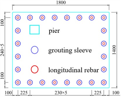
This study is based on a prefabricated bridge from the Jining Inner Ring Elevated and Connection Project, which is adopted as the engineering prototype. The geometric configuration of the prototype is illustrated in Fig. 1. In this bridge system, grouted sleeve connections are arranged at the pier base. Each sleeve has a length of 800 mm, an external diameter of 95 mm, and an inner diameter of 40 mm. The longitudinal reinforcing bars are embedded 400 mm into the sleeve from each end. Detailed information on the reinforcement and sleeve configuration is provided in Fig. 2 [38].
Fig. 1Dimensional detail of precast prefabricated pier (unit: m)
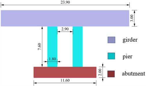
a) Main view
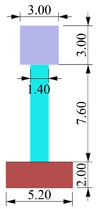
b) Side view
2.1. Numerical simulation program
The objective of this study is to evaluate the seismic performance of prefabricated piers and compare them with conventional cast-in-place piers, with particular emphasis on the influence of pier configuration on hysteretic behavior and damage evolution in prefabricated systems. Using a control-variable approach, the cross-sectional areas of single-column and three-column piers are calibrated based on equivalent cap beam dimensions. Finite element models are subsequently developed in ABAQUS to simulate the structural response. To represent seismic actions, quasi-static cyclic loading with low-amplitude displacement control is applied to the pier models [38]. The seismic performance is evaluated from two perspectives: hysteretic behavior and failure mechanisms. The specimen configurations considered in this study are summarized in Table 1.
Fig. 2Detailed drawing of grouting sleeve arrangement form (unit: mm)
Specimens A1 and A2 represent double-column pier configurations with identical overall geometries (see Fig. 1). Specimen A1 corresponds to a prefabricated pier, whereas A2 represents the conventional cast-in-place counterpart, consisting of four primary components: pier shaft, cap beam, bearings, and reinforcement. The prefabricated configuration differs from the cast-in-place system by incorporating grouted sleeve connections at the pier base. Specimens B1 and B2 are both prefabricated configurations, with B1 representing a single-column pier and B2 a three-column pier system. Their geometric details are illustrated in Figs. 2-3. Group A specimens (A1 and A2) differ in construction method, providing a basis for comparing the seismic performance of prefabricated and cast-in-place piers. Group B specimens (A1, B1, and B2) vary in pier configuration, enabling investigation of the influence of pier number on the seismic behavior of prefabricated bridge systems. The detailed dimensions of B1 and B2 are presented in Figs. 3-4, while their elevation views are consistent with that of specimen A1. All specimens share identical abutment dimensions, material properties, and boundary conditions. In addition, the connection detailing of all prefabricated specimens is kept consistent to ensure a controlled comparison.
Fig. 3Dimensional detail of specimen B1 (unit: m)
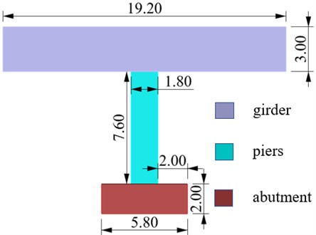
Fig. 4Dimensional detail of specimen B2 (unit: m)
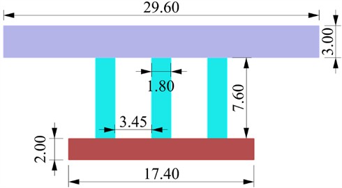
Table 1Specimen parameters
Specimen | Bridge form | Piers and columns arrangement form |
A1 | Prefabricated bridge | Double-column pier |
A2 | Traditional cast-in-place double-column piers | Double-column pier |
B1 | Prefabricated bridge | Single-column bridge |
B2 | Prefabricated bridge | Three-column bridge |
2.2. Unit types and material architecture
In the finite element modeling process, three-dimensional solid elements were adopted to represent the piers, cap beams, bearing platforms, reinforcement, and grouted sleeves. Specifically, eight-node linear brick elements with reduced integration (C3D8R) were used to model both concrete components – such as piers, cap beams, and bearing platforms – and steel components, including reinforcement and grouted sleeves. Mesh sensitivity analysis was conducted to ensure the accuracy and convergence of the numerical results.
In the finite element model, the piers were assigned C50 concrete, while C35 concrete was used for the cap beams and bearing platforms. The grouted sleeves were assumed to be composed of high-strength ductile iron, and HRB400 steel was adopted for the reinforcement. Due to their relatively high stiffness, the grouted sleeves remained in the elastic regime throughout the seismic analysis, without exhibiting noticeable plastic deformation. Therefore, they were modeled using a linear elastic constitutive model, with a density of 7800 kg/m3, an elastic modulus of 2.1×10⁵ MPa, and a Poisson’s ratio of 0.3. The reinforcement was modeled using an elastic–plastic constitutive relationship. It behaved elastically prior to yielding and gradually entered the plastic stage as the load increased and concrete damage developed. The material parameters for the reinforcement were defined as follows: density of 7850 kg/m3, elastic modulus of 2.1×10⁵ MPa, Poisson’s ratio of 0.3, and yield strength of 450 MPa. Concrete was simulated using the concrete damaged plasticity (CDP) model to capture its nonlinear behavior under seismic loading, including cracking, crushing, and stiffness degradation. This model enables accurate representation of damage evolution and failure mechanisms in concrete components such as piers and cap beams. The material properties of concrete include a density of 2450 kg/m3, an elastic modulus of 32,500 MPa, and a Poisson’s ratio of 0.2 [39, 40]. Additional CDP parameters are listed in Table 2, and the corresponding stress – strain relationships are presented in Fig. 5.
Table 2Concrete material parameters
Materials | Shear angle | fb0/fc0 | Offset | Coefficient of viscosity | |
Concrete | 30 | 0.6667 | 1.16 | 0.1 | 0.0001 |
Fig. 5Concrete strength stress-strain curve
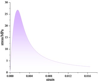
a) Stress-strain curve of concrete under compression
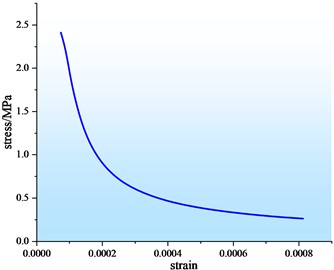
b) Stress-strain curve of concrete in tension
2.3. Contact definition and meshing
In the ABAQUS simulation, appropriate definitions of contact interactions and mesh discretization are essential to ensure numerical convergence and solution accuracy. The contact formulations were selected to realistically represent the mechanical behavior and interaction characteristics of different structural components.
Under seismic loading, the interface between the pier base and the bearing platform was modeled using a surface-to-surface contact formulation, allowing for potential sliding and separation. In practical engineering, the connection between reinforcement and grouted sleeves is typically achieved using high-strength, non-shrink grout. However, explicitly modeling this complex interaction may significantly increase computational cost and reduce convergence efficiency. Therefore, this connection was simplified as a steel-to-steel interaction. To account for possible slip under seismic loading, a surface-to-surface contact definition was also adopted for this interface. Furthermore, considering that the reinforcement, grouted sleeves, piers, and bearing platforms are expected to act in a fully bonded manner in the actual structure, an embedded region constraint was employed to simulate their interaction. This approach assumes perfect bond behavior and eliminates the need for explicit contact definitions, thereby improving computational efficiency and model stability [38, 41].
Fig. 6Model meshing
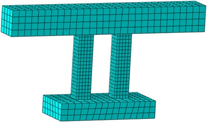
A structured meshing strategy was adopted, in which all components were discretized into hexahedral elements. Specifically, C3D8R elements (eight-node linear brick elements with reduced integration) were used. After mesh sensitivity analysis and iterative refinement, the final mesh configuration is shown in Fig. 6. During the computation, the default convergence criteria of the ABAQUS solver were adopted. Upon completion of the analysis, the mechanical responses of all components were compared against empirical ranges and found to be within reasonable bounds, thereby confirming the convergence of the model.
2.4. Boundary conditions and loading regime
In the actual service condition of the bridge, the pile cap is typically embedded in the surrounding soil, such that its base can be reasonably assumed to be fully restrained, with no translational or rotational degrees of freedom. Accordingly, in the numerical simulation, all displacement and rotational degrees of freedom in the -, -, and -directions were fixed at the bottom surface of the pile cap to realistically represent the boundary conditions. The loading protocol follows that adopted in a previous study by the authors [35]. The static loading applied to the bridge includes both self-weight and superimposed dead loads from the deck system. Specifically, gravitational loading was applied to the entire structure, while a uniformly distributed load was imposed on the top of the girder to simulate the effects of deck pavement and associated loads. To eliminate the influence of varying axial compression ratios, the magnitude of the applied uniform load was adjusted for each specimen to ensure that an identical axial compression ratio was maintained at the pier top.
Seismic analysis of bridge structures is commonly conducted using two primary approaches: dynamic analysis and quasi-static simulation. The dynamic analysis method applies recorded or synthetic ground motion inputs to the structure, providing a realistic representation of seismic response. However, its results are highly sensitive to factors such as peak ground acceleration and the frequency content of the input motions. In contrast, the quasi-static simulation method reproduces seismic effects by applying low-frequency cyclic lateral loading, enabling detailed evaluation of hysteretic behavior, stiffness degradation, and damage evolution. It also facilitates the identification of key response states, such as yielding and ultimate failure of concrete components. Accordingly, this study adopts a quasi-static cyclic loading protocol to investigate the seismic performance of the bridge piers. Cyclic displacement is applied at the cap beam in the transverse direction. The loading is displacement-controlled, with an initial amplitude of 20 mm, which is incrementally increased by 20 mm per loading step up to a maximum amplitude of 200 mm. Each displacement level is repeated for two complete cycles, with each cycle consisting of both forward and reverse loading. The lateral load is applied at the mid-height of the side surface of the cap beam. The loading configuration and direction are illustrated in Fig. 7.
Fig. 7Schematic diagram of the loading system
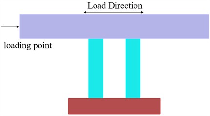
a) Loading direction
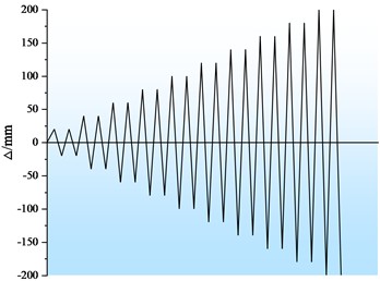
b) Loading system
2.5. Results comparison transformation
The bending moment of inertia of each specimen can be obtained according to the bending moment of inertia calculation formula and the detailed dimensions of the model:
Specimen A1: 3756.06 mm4.
Specimen B1: 1805.68 mm4.
Specimen B2: 8216.78.
2.08.
0.46.
Taking specimen A1 as the reference model, a scaling procedure was implemented based on the ratio of flexural moments of inertia among different pier configurations. Under the assumption of equal displacement demand, the numerical results were transformed to evaluate the seismic performance of prefabricated piers with varying pier configurations, while preserving the stress distribution and plastic zone patterns. The load-carrying capacity of each configuration was subsequently scaled in proportion to the corresponding moment of inertia ratio.
3. Calibration of numerical analysis results
To validate the reliability of the numerical simulation approach, a previously reported quasi-static cyclic test on a prefabricated pier with grouted sleeve connections was reproduced. A corresponding finite element model of the tested specimen was established following the modeling methodology described above. The numerical results were subsequently compared with the experimental data to evaluate the accuracy and predictive capability of the proposed modeling approach.
3.1. Introduction to the test program
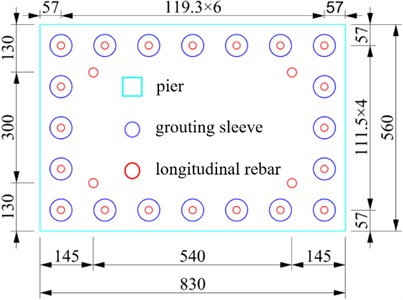
The quasi-static cyclic test reported in the literature provides a validation benchmark for this study [35]. Specimen PCTS from the referenced experiment was adopted as the calibration model. The geometric configuration of the specimen is illustrated in Fig. 8, while the arrangement of the grouted sleeves and longitudinal reinforcement within the pier cross-section is shown in Fig. 9. In the finite element model, the geometric dimensions and material properties of the reinforcement, grouted sleeves, and concrete were defined to be consistent with those used in the experimental program.
Fig. 8Details of specimen size (unit: mm)
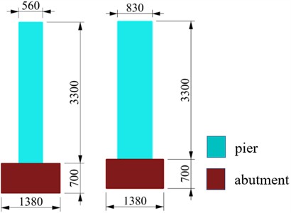
Fig. 9Column section reinforcement diagram (unit: mm)
In the experimental protocol, a constant axial load of 1080 kN was applied to the specimen. Initially, load-controlled conditions were employed to capture the structural response from the undamaged state up to the onset of concrete cracking. Subsequently, the loading mode was switched to displacement-controlled loading to evaluate the ductility capacity of the specimen. The numerical simulation replicated this loading sequence and control strategy, enabling direct comparison between the simulated and experimental responses.
3.2. Numerical simulation verification
Fig. 10 presents the skeleton curves obtained from both the numerical simulation and the experimental results. A close agreement is observed between the two curves, with consistent trends and comparable peak responses, thereby validating the reliability of the numerical model under identical loading conditions.
Fig. 10Comparison of experimental and numerical simulated skeleton curves
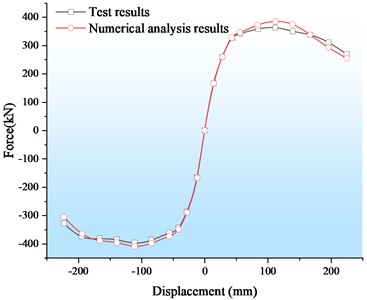
Fig. 11Schematic diagram of the plastic region of concrete
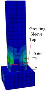
Table 3 compares the key strength and deformation parameters derived from the load-displacement responses of the prefabricated specimen. The results indicate that the numerical predictions are in good agreement with the experimental data, with a maximum deviation of only 5.7 %. This level of accuracy demonstrates the strong predictive capability of the proposed finite element model. Minor discrepancies between the numerical and experimental results can be attributed to several factors. First, variations in material properties exist between the numerical model and the physical test. While standard material parameters were adopted in the simulation, the actual strengths of concrete, reinforcement, and grouted sleeves in the experiment may slightly exceed their nominal values. Second, uncertainties inherent in the experimental process-such as concrete compaction quality and the bond performance between reinforcement and grouted sleeves-can influence the measured response. In contrast, the numerical model assumes idealized conditions, which may also contribute to the observed differences.
Table 3Numerical values of strength and deformation characteristics obtained by experiment and numerical simulation
Load / kN | Displacement / mm | |||
Yield | Ultimate | Yield | Ultimate | |
Test result | 323.1 | 364.3 | 40.6 | 207.2 |
Numerical simulation results | 338.7 | 385.3 | 38.5 | 195.9 |
Error | 4.8 % | 5.7 % | 5.2 % | 5.4 % |
The experimental results indicate that the crushed concrete region extended to approximately 650 mm above the top of the grouted sleeve. The corresponding plastic damage distribution predicted by the numerical simulation is shown in Fig. 11. It can be observed that both the location and the extent of the most severely damaged concrete region in the simulation are in close agreement with the experimental observations. This consistency further confirms the reliability and validity of the adopted numerical modeling approach in capturing the damage characteristics of the prefabricated pier.
4. Analysis of influencing factors
4.1. Sleeve length
4.1.1. Hysteresis performance
Hysteresis curves play a fundamental role in characterizing the deformation capacity, stiffness degradation, and energy dissipation of structures under cyclic loading, thereby providing a basis for nonlinear seismic response analysis. By connecting the peak points of successive hysteresis loops, the skeleton curve represents the overall force–deformation evolution of a structural component and identifies key response stages, including yielding, peak strength, and post-peak degradation. In this study, the yield point was determined using the general yield moment method. The peak load capacity was defined as the maximum ordinate of the skeleton curve, while the ultimate displacement was taken as the displacement corresponding to 85 % of the peak load. The cumulative hysteretic energy dissipation was calculated as the total enclosed area of all hysteresis loops, representing the energy absorbed by the structure during cyclic loading. In addition, residual displacement, which reflects the irreversible deformation after unloading, was adopted as an important indicator of seismic performance. Accordingly, the hysteretic behavior of the prefabricated piers was evaluated from four aspects: hysteresis curves, skeleton curves, cumulative energy dissipation, and residual displacement.
(1) Hysteresis curve.
A finite element model was established and analyzed under quasi-static cyclic loading. The hysteresis curves, representing the relationship between horizontal load and lateral displacement at the pier top for Group A specimens, are presented in Fig. 12. As shown, the hysteresis loops of the Group A specimens exhibit similar shapes, indicating consistent hysteretic behavior among the specimens. This similarity suggests that, despite differences in structural type (prefabricated versus cast-in-place), the cyclic response characteristics – including stiffness degradation, pinching effect, and energy dissipation – follow a comparable trend. This observation further supports the validity of comparing these models in subsequent analyses.
Fig. 12Hysteretic curve of Group A specimen
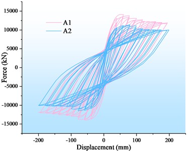
Fig. 13Skeleton curve of Group A specimen
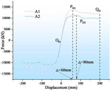
(2) Skeleton curve.
The skeleton curves of the Group A specimens are presented in Fig. 13. As shown, the curves exhibit an initial linear increase in the elastic stage, followed by a gradual nonlinear rise upon entering the plastic stage, and finally a descending branch after reaching the peak load. Prior to the peak point, the load-carrying capacity increases with increasing displacement, whereas beyond the peak, strength degradation occurs as displacement continues to grow. Combined with the data in Table 4, it is observed that specimen A1 (prefabricated) exhibits higher yield and peak loads than specimen A2 (cast-in-place), while A2 shows a larger peak displacement. Specifically, the yield loads of A1 and A2 are 12148.7 kN and 10213.2 kN, corresponding to yield displacements of 32.57 mm and 31.66 mm, respectively. The peak loads are 14100.0 kN and 12800.0 kN, with corresponding peak displacements of 59.80 mm (PD1) and 79.85 mm (PD2), respectively. Overall, the prefabricated pier with grouted sleeve connections demonstrates yield and peak loads that are 18.9 % and 10.1 % higher than those of the cast-in-place pier, respectively. In contrast, its peak displacement is 25.1 % lower, while the yield displacements of the two specimens are comparable. These results indicate that the prefabricated specimen possesses higher strength but relatively lower deformation capacity. Nevertheless, the cast-in-place specimen exhibits a larger ductility coefficient, suggesting superior ductility performance. This behavior can be attributed to the increased local stiffness introduced by the grouted sleeve connection, which enhances strength but restricts deformation development.
Fig. 14Cumulative energy dissipation of Group A specimen
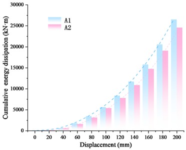
Fig. 15Residual displacement of Group A specimen
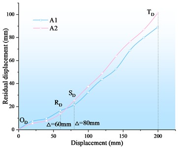
Table 4Group B specimen strength and deformation characteristics of numerical value
Specimen | Load direction | Yield | Ultimate | Ductility factor | ||
Force (kN) | Displacement (mm) | Force (kN) | Displacement (mm) | |||
A1 | Positive | 11907.0 | 32.57 | 14100.0 | 59.80 | 5.72 |
Negative | 12148.7 | 30.15 | 13900.0 | 58.66 | 7.04 | |
A2 | Positive | 10575.0 | 31.66 | 12800.0 | 79.85 | 9.30 |
Negative | 10771.7 | 28.26 | 12700.0 | 78.64 | 12.33 | |
(3) Cumulative energy dissipation.
Fig. 14 presents the cumulative hysteretic energy dissipation of the Group A specimens, which increases monotonically with loading displacement. Throughout the loading process, specimen A1 (prefabricated) consistently dissipates more energy than specimen A2 (cast-in-place). The cumulative energy dissipation of A1 and A2 reaches 26513.6 kN·m and 22878.1 kN·m, respectively. Overall, the prefabricated pier with grouted sleeve connections exhibits superior energy dissipation compared with the cast-in-place pier. Quantitatively, the cumulative energy dissipation of the prefabricated specimen is 15.9 % higher than that of its cast-in-place counterpart. This enhanced energy dissipation capacity can be attributed to the improved load transfer and confinement effect provided by the grouted sleeve connection, which promotes more stable hysteretic behavior under cyclic loading.
(4) Residual displacement.
Fig. 15 presents the residual displacements of the Group A specimens, which increase progressively with loading displacement. Within the 0-60 mm range (OARA segment), specimen A1 (prefabricated) exhibits smaller residual displacements than specimen A2 (cast-in-place). However, in the 100-200 mm range (SATA segment), the residual displacement of A1 exceeds that of A2. At a loading displacement of 200 mm, the residual displacements of A1 and A2 are 89.1 mm and 85.7 mm, respectively.
Overall, before reaching the peak load, the cast-in-place specimen exhibits larger residual displacements than the prefabricated specimen, as both remain in the elastic and early elastic-plastic stages. This behavior is attributed to the higher stiffness of the prefabricated pier, which enables more effective recovery after unloading. However, near and beyond the peak load, the prefabricated specimen shows slightly larger residual displacements (by approximately 4.0 %), indicating a reduction in self-centering capability. These results suggest that, although the prefabricated double-column pier demonstrates higher stiffness and strength, its post-peak deformation recovery capacity is relatively weaker than that of the cast-in-place pier. This highlights the importance of incorporating self-centering or recentering design strategies in prefabricated bridge systems to enhance seismic resilience.
4.1.2. Damage mechanism
The objective of this analysis is to identify vulnerable regions and stress concentration zones in bridge piers under seismic loading by examining the evolution of stress distribution and the development of plastic zones during displacement-controlled loading. Prior to the application of lateral displacement, the bridge model is subjected to gravity load and a uniform load applied on the cap beam. During the loading process, the specimens reach their peak loads at displacements of 59.80 mm and 79.85 mm, respectively. Accordingly, the damage mechanism analysis focuses on the stress distribution and plastic zone contours at the instances when the forward displacement first reaches 60 mm and 80 mm.
(1) Stress development.
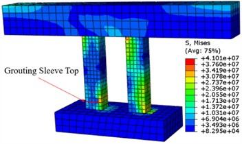
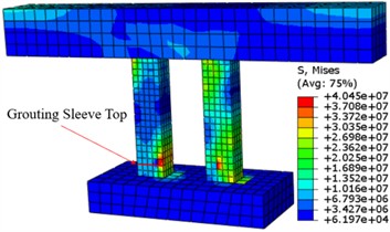
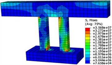
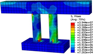
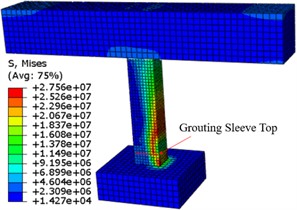
The stress distribution contours of the Group A specimens are presented in Figs. 16-17. During displacement-controlled loading, the stress states of the cap beam and bearing platform remain largely unchanged, while significant variations are observed in the piers. At a displacement of 60 mm, pronounced stress concentrations develop in the piers of both specimens, primarily located at the upper left and lower right regions. This distribution is influenced by the interaction between the two columns and the cap beam, which results in similar stress patterns in the upper portions of the piers. For specimen A1 (prefabricated), the presence of grouted sleeve connections increases local stiffness, leading to a stress distribution below the sleeve that resembles that at the pier base. In contrast, specimen A2 (cast-in-place) exhibits a more pronounced stress concentration at the pier bottom.
Fig. 16Stress cloud of specimen A1
a) 60 mm
b)80 mm
When the displacement increases to 80 mm, the overall stress distribution pattern remains similar, but the stress magnitude becomes significantly higher. In particular, specimen A1 at 60 mm and specimen A2 at 80 mm exhibit intensified stress levels, corresponding to their respective states near peak load. This behavior is consistent with the hysteretic response as the piers approach their maximum load-carrying capacity under cyclic loading. Overall, stress concentrations in the prefabricated piers are primarily distributed at the pier top and in the lower region near the grouted sleeve, whereas in the cast-in-place piers, stress concentrations are mainly located at both the top and bottom ends. This indicates that the grouted sleeve connection modifies the load transfer path and redistributes stresses along the pier height, thereby reducing excessive stress concentration at the base.
Fig. 17Stress cloud of specimen A2
a) 60 mm
b)80 mm
(2) Plastic region development.
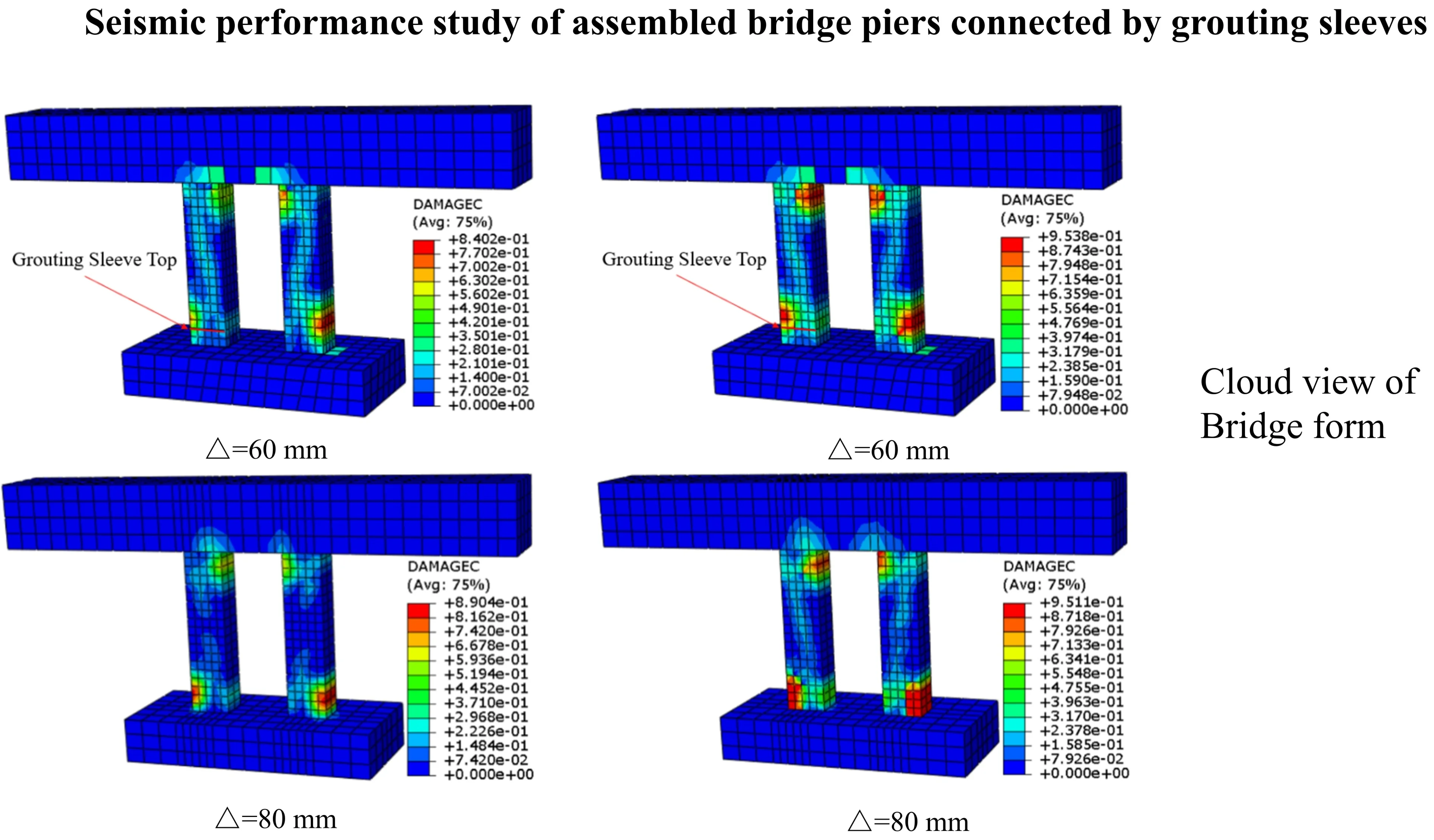
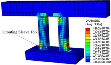
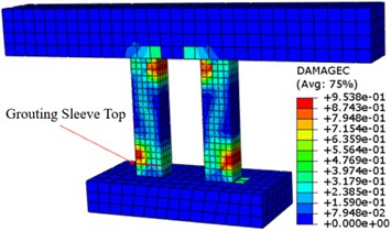
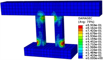
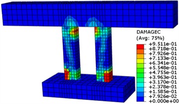
Figs. 18-19 present the plastic zone contours of the Group A specimens. During displacement-controlled loading, plasticity in the cap beam and bearing platform is primarily confined to their connection regions with the piers, while other areas exhibit relatively minor damage. In contrast, significant plastic development is observed in the piers. For specimen A1 (prefabricated), plastic zones initially concentrate at the pier top and in the region just above the grouted sleeve. At a displacement of 60 mm, a plastic zone emerges at the mid-height of the pier, indicating the initiation of distributed damage.
Fig. 18Cloud view of the plastic region of specimen A1
a) 60 mm
b)80 mm
Fig. 19Cloud view of plastic region of specimen A2
a) 60 mm
b)80 mm
With increasing displacement, this mid-height plastic zone expands significantly, accompanied by a continuous increase in the damage factor. At 80 mm displacement, the plastic zones in the piers further enlarge and intensify, reflecting progressive damage evolution. In contrast, specimen A2 (cast-in-place) exhibits plastic zones predominantly concentrated at the top and bottom regions of the pier, indicating a more typical flexural failure mode with plastic hinges forming near the ends. Overall, the presence of grouted sleeve connections in the prefabricated piers increases the stiffness of the lower pier region, which alters the load transfer mechanism and promotes an upward shift of the plastic zone. This results in the formation of a distributed plastic region above the sleeve and at the pier top, rather than severe damage localization at the base. Such a shift in plastic zone distribution suggests a mitigation of base damage and a modification of the failure mode from concentrated to more distributed plastic deformation.
4.2. Reinforcement diameters
4.2.1. Hysteresis performance
(1) Hysteresis curve.
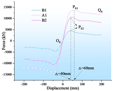
The hysteresis curves of the Group B specimens are presented in Fig. 20. All specimens exhibit broadly similar loop shapes, indicating consistent cyclic behavior. However, a clear stepped pattern in the hysteresis response is observed. In terms of load level, the curves rank from highest to lowest as A1, B2, and B1. This hierarchical distribution reflects differences in lateral stiffness and structural configuration among the specimens. Specimen A1 demonstrates the highest lateral stiffness and strongest resistance to deformation, followed by B2 and then B1. As the number of columns decreases, the structural stiffness is reduced, leading to lower load-carrying capacity and more pronounced deformation under cyclic loading.
Fig. 20Hysteretic curve of Group C specimen
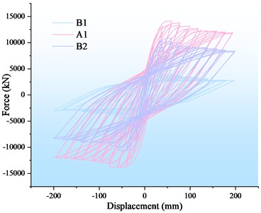
Fig. 21Skeleton curve of Group C specimen
(2) Skeleton curve.
The skeleton curves of the Group B specimens are shown in Fig. 21. All curves exhibit an initial linear ascending branch, followed by a nonlinear stage with reduced stiffness, and finally a descending branch after reaching peak load capacity, indicating structural degradation. Throughout the loading process, the load-carrying capacities of specimens A1, B2, and B1 consistently follow a descending order, forming a distinct stepped pattern. As summarized in Table 5, the load–displacement responses indicate that the bearing capacity of all specimens increases with displacement prior to the peak load, and subsequently decreases with further displacement, reflecting post-peak softening behavior. The yield loads of specimens B1, A1, and B2 are 4204.5 kN, 12148.7 kN, and 9213.9 kN, respectively, while the corresponding peak load capacities are 4742.9 kN, 14100.0 kN, and 10815.9 kN. The yield displacements are 33.42 mm, 32.57 mm, and 32.56 mm, respectively, and the ultimate displacements are 59.80 mm, 54.03 mm, and 58.17 mm. Among them, specimen B1 exhibits the largest yield displacement, whereas specimen A1 shows the smallest. Overall, for prefabricated piers connected by grouted sleeves with equivalent moments of inertia, the structural performance is strongly influenced by the column configuration. The yield load, peak load capacity, and ductility coefficient follow the order: double-column > three-column > single-column piers. Compared with the double-column configuration, the yield loads of single-column and three-column piers decrease by 65.4 % and 24.2 %, respectively, while the peak load capacities decrease by 66.4 % and 23.3 %, respectively. These results indicate that increasing the number of columns significantly enhances lateral stiffness and load-carrying capacity, while also improving the overall seismic performance of prefabricated bridge piers.
Fig. 22Cumulative energy dissipation capacity of Group C specimen
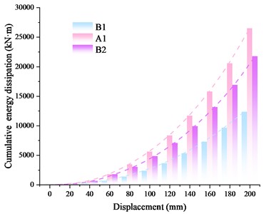
Fig. 23Residual displacement of Group C specimen
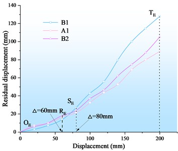
Table 5Group C specimen strength and deformation characteristics of numerical value
Specimen | Load direction | Yield | Ultimate | Ductility factor | ||
Force (kN) | Displacement (mm) | Force (kN) | Displacement (mm) | |||
B1 | Positive | 4069.5 | 33.42 | 4742.9 | 56.16 | 2.20 |
Negative | 4204.5 | 30.23 | 4742.9 | 58.17 | 3.05 | |
A1 | Positive | 11907.0 | 32.57 | 14100.0 | 59.80 | 5.72 |
Negative | 12148.7 | 30.15 | 13900.0 | 58.66 | 7.04 | |
B2 | Positive | 9213.9 | 32.56 | 10815.9 | 54.03 | 4.11 |
Negative | 9212.6 | 28.49 | 10722.6 | 48.84 | 4.69 | |
(3) Accumulated energy dissipation.
Figure 22 illustrates the cumulative hysteretic energy dissipation capacity of the Group B specimens, which increases monotonically with loading displacement. Throughout the loading process, a clear hierarchical trend is observed, with the energy dissipation capacity ranking as A1 > B2 > B1. At a displacement of 200 mm, the cumulative energy dissipation values of specimens A1 and B2 reach 26513.6 kN·m and 21759.5 kN·m, respectively. This stepped distribution is consistent with the differences in structural stiffness and load-carrying capacity among the specimens. Overall, for prefabricated piers connected by grouted sleeves with identical bending moments of inertia, the cumulative energy dissipation capacity follows the order: double-column > three-column > single-column. Compared with the double-column configuration, the cumulative energy dissipation of single-column and three-column piers decreases by 53.4 % and 17.9 %, respectively. These results indicate that increasing the number of columns significantly enhances the energy dissipation capacity of the structure, thereby improving its seismic energy absorption capability under cyclic loading.
(4) Residual displacement.
Fig. 23 presents the residual displacements of the Group B specimens, showing a continuous increase with loading displacement. In the 0-60 mm range (OERE segment), the residual displacements of specimens A1 and B2 are nearly identical and both exceed that of specimen B1. However, in the 80-200 mm range, the ranking reverses to B1 > B2 > A1, indicating a change in deformation characteristics as damage accumulates. At a displacement of 200 mm (SETE segment), the residual displacements of specimens B1, B2, and A1 are 127.8 mm, 105.1 mm, and 89.1 mm, respectively.
In summary, for grouted-sleeve-connected prefabricated piers with identical bending moments of inertia, the residual displacement follows the order: double-column < three-column < single-column. Compared with the double-column configuration, the residual displacements of single-column and three-column piers increase by 43.4 % and 17.9 %, respectively. This trend indicates that structures with fewer columns exhibit reduced stiffness and weaker self-centering capability, leading to larger irreversible deformations after unloading. In contrast, the double-column configuration demonstrates superior stiffness retention and enhanced self-centering performance. From an engineering perspective, prefabricated double-column piers exhibit smaller residual displacements and are therefore more favorable for post-earthquake recovery. Adopting a double-column configuration in bridge design can effectively reduce permanent deformation and facilitate structural re-centering, thereby improving seismic resilience and post-disaster serviceability.
4.2.2. Damage mechanism
For the Group B specimens, the ultimate load-bearing capacity is reached at forward displacements of 40 mm and 60 mm. To investigate the damage mechanisms of the prefabricated piers, stress and plastic-zone contour plots are extracted at the first instances when the forward displacement reaches 40 mm and 60 mm, respectively.
(1) Stress development.
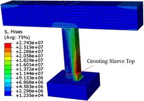
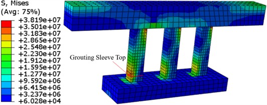
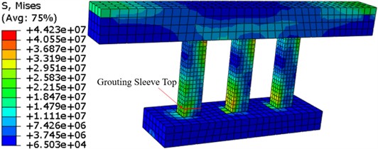
The stress contour plots of the Group B specimens are shown in Figs. 16 and 24-25. It can be observed that the stress distribution varies significantly with the structural configuration. For the single-column pier, no pronounced stress concentration is observed at the pier top. Instead, stress is primarily concentrated in the region above the grouting sleeve. As the displacement increases to the ultimate load state, the stress concentration zone expands laterally, indicating progressive stress redistribution and damage propagation in this region. For the three-column piers, the stress distribution pattern is generally consistent with that of the double-column piers. Significant stress concentrations are observed both at the pier top and in the lower regions above the grouting sleeves.
Fig. 24Stress cloud of specimen B1
a) 40 mm
b)0 mm
This indicates that these locations act as critical sections under cyclic loading. Under positive displacement loading, the left pier in the three-column configuration exhibits a markedly higher stress concentration compared to the two right piers. Moreover, throughout the cyclic loading process, the outer piers consistently experience higher stress levels than the middle pier. This non-uniform stress distribution can be attributed to the interaction among columns and the asymmetric load transfer mechanism within the multi-column system. The outer columns are more directly involved in resisting lateral loads, resulting in higher stress demands, while the middle column contributes comparatively less to lateral resistance. Overall, the stress concentration locations in Group B specimens are strongly influenced by the column configuration. In single-column piers, stress is mainly concentrated above the grouting sleeve, whereas in multi-column piers, stress concentrations occur both at the pier top and near the sleeve region. These findings highlight the critical role of structural configuration in governing stress distribution and potential damage initiation zones.
Fig. 25Stress cloud of specimen B2
a) 40 mm
b)0 mm
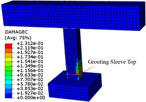
(2) The plastic zone distributions of the Group B specimens are presented in Figs. 18 and 26-27. It can be observed that the development of plastic zones varies significantly with the structural configuration. For the single-column pier, the plastic zone is primarily concentrated above the grouted sleeve in the lower region of the pier, with no evident plastic development near the pier top. This indicates that damage is highly localized, forming a dominant plastic hinge near the base of the pier. In contrast, the double- and three-column piers exhibit additional plastic zones near the pier top, along with those in the lower regions above the sleeves. This suggests a more distributed plastic deformation pattern, with multiple potential plastic hinge regions forming along the pier height. This difference can be attributed to the structural system characteristics. The single-column pier behaves as a statically determinate system, leading to concentrated internal force demand and localized damage. In contrast, the double- and three-column piers are statically indeterminate systems, which allow for load redistribution among columns, thereby reducing damage concentration in any single location. As a result, the plastic zone in the lower region of the single-column pier is more extensive and exhibits more severe damage. Conversely, the double- and three-column piers show smaller and less concentrated plastic regions, indicating improved damage distribution and enhanced structural redundancy.
Fig. 26Cloud view of plastic region of specimen B1
a) 40 mm
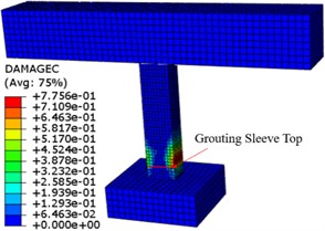
b)0 mm
Fig. 27Cloud view of the plastic region of specimen B2
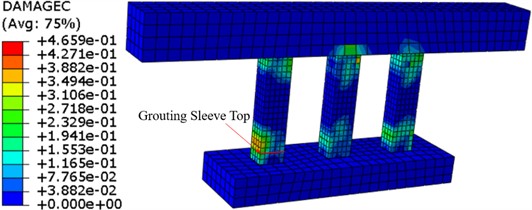
a) 40 mm
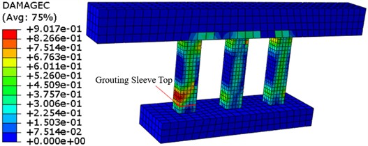
b)0 mm
After loading, the plastic zones in the two columns of the double-column pier are nearly symmetrical, with comparable damage levels. However, in the three-column configuration, the plastic zones in the outer columns are significantly larger than that in the central column, indicating that damage is more concentrated in the outer columns. This behavior is consistent with the stress distribution characteristics, where the outer columns carry higher lateral load demands. It further demonstrates that column interaction and load redistribution play a critical role in governing damage evolution in multi-column prefabricated piers.
5. Discussion
Prefabricated bridges offer significant advantages and promising applications, especially given advances in construction and assembly technologies. Nevertheless, their seismic theory remains imperfect. Unlike traditional cast-in-place piers, prefabricated bridges comprise components such as piers and cover girders that are prefabricated off-site and later prefabricated on location. Although less monolithic than cast-in-place systems, their seismic response is more complex. Many researchers have extensively studied damage modes and mechanisms in prefabricated bridges connected via grouting sleeves; however, these studies have largely focused on single-column piers, with far fewer investigations into double-column bridge piers despite their more widespread use. Moreover, the differences in seismic performance among prefabricated bridges with different pier and column arrangements remain unclear. In this study, using ABAQUS simulation, we developed finite element models for prefabricated two-column bridges and cast-in-place two-column bridges of identical geometry. By applying cyclic displacement to simulate seismic action, we analyzed and compared the hysteretic performance and damage mechanisms of both types. This allowed us to clarify the seismic performance differences between prefabricated and cast-in-place two-column bridges, and to further explore how different pier/column arrangement forms affect performance in prefabricated bridges.
This study validated the numerical simulation method through comparison with existing experimental tests. Using real-world project geometry, refined finite element models of both prefabricated two-column and cast-in-situ two-column bridges were developed. A cyclic displacement protocol (quasi-static loading) was applied to simulate seismic demand, enabling analysis of the hysteretic behavior and damage mechanisms of both bridge types. Furthermore, the effect of different pier/column arrangements on the performance of prefabricated piers was investigated. The influence of pier column layout on the seismic performance of prefabricated piers is mainly due to the difference of bending moment of inertia under different pier column layouts. Therefore, in the high intensity area, the design of prefabricated piers should improve the bending moment of inertia as much as possible under the same volume to improve its seismic performance. However, it should be noted that the damage modes predicted by the quasi-static method were not reproduced with the same fidelity as those observed in shaking table tests. As a result, conclusions concerning damage patterns under seismic excitation are less comprehensive, particularly with respect to localized cracking, inertial effects, strain rate influences, and interaction among components.
6. Conclusions
Prefabricated bridge systems exhibit significant advantages in terms of construction efficiency and structural performance, demonstrating strong potential for application in seismic regions. Based on a prototype engineering background, this study presents a systematic numerical investigation into the seismic behavior of prefabricated bridge piers with grouted sleeve connections, in comparison with conventional cast-in-place double-column piers. In addition, the effects of pier-column configuration on seismic performance are comprehensively evaluated. The findings provide both mechanistic insights and design-oriented guidance for the application of prefabricated bridge systems in high-intensity seismic zones. The principal conclusions are as follows:
1) Prefabricated double-column piers exhibit superior peak load capacity and energy dissipation capacity compared with cast-in-place piers, whereas the latter demonstrate enhanced ductility. This trade-off is governed by the stiffness discontinuity introduced by grouted sleeve connections near the pier base. The localized stiffness amplification constrains plastic deformation development and limits global deformation capacity, thereby leading to reduced ductility in prefabricated systems.
2) Under the condition of equivalent flexural stiffness (i.e., identical moment of inertia), pier-column configuration plays a decisive role in seismic performance. The double-column configuration consistently achieves the highest load-bearing capacity, greatest energy dissipation, and smallest residual displacement, followed by the three-column configuration, while the single-column configuration exhibits the weakest performance. This hierarchy highlights the critical role of structural redundancy and force redistribution in enhancing seismic resilience.
3) A key mechanistic finding of this study is that the presence of grouted sleeve connections alters the damage evolution pattern by shifting the plastic hinge region upward from the pier base to the region immediately above the sleeve. Consequently, stress concentration and plastic damage are predominantly distributed at the pier top and in the lower region above the sleeve, forming a dual critical damage zone along the pier height.
4) The seismic vulnerability of pier systems is strongly dependent on structural determinacy. The single-column pier, as a statically determinate system, exhibits highly localized stress concentration and extensive plastic damage, indicating limited capacity for damage redistribution. In contrast, multi-column systems (double- and three-column piers), characterized by structural redundancy, enable more distributed plasticity through load redistribution mechanisms. Notably, in three-column configurations, damage is preferentially concentrated in the outer columns, while the central column remains relatively less engaged.
5) From a performance-based perspective integrating hysteretic response, energy dissipation, residual displacement, and damage distribution, the seismic performance of different configurations can be ranked as: double-column > three-column > single-column. The double-column configuration achieves an optimal balance between strength, deformation capacity, and post-earthquake recoverability, and is therefore recommended as a preferred design solution for prefabricated bridge piers in seismic regions. Overall, this study elucidates the interaction mechanism among connection form, structural configuration, and damage evolution in prefabricated bridge piers, and provides a theoretical and practical basis for seismic design and optimization of prefabricated bridge systems.
References
-
Y. Liu, X. Li, X. Zheng, and Z. Song, “Experimental study on seismic response of precast bridge piers with double-grouted sleeve connections,” Engineering Structures, Vol. 221, No. 99, p. 111023, Jul. 2020, https://doi.org/10.1016/j.engstruct.2020.111023
-
J. Jia et al., “Seismic evaluation of precast bridge columns with built-in elastomeric pads,” Soil Dynamics and Earthquake Engineering, Vol. 128, p. 105868, Sep. 2019, https://doi.org/10.1016/j.soildyn.2019.105868
-
Y. Han, J. Dong, and L. Wang, “Experimental study on the seismic performance of socket bridge piers,” Advances in Civil Engineering, Vol. 2020, No. 1, Nov. 2020, https://doi.org/10.1155/2020/8895196
-
C. Li, H. Hao, X. Zhang, and K. Bi, “Experimental study of precast segmental columns with unbonded tendons under cyclic loading,” Advances in Structural Engineering, Vol. 21, No. 3, pp. 319–334, Jun. 2017, https://doi.org/10.1177/1369433217717119
-
J. D. Nzabonimpa and W.-K. Hong, “Structural performance of detachable precast composite column joints with mechanical metal plates,” Engineering Structures, Vol. 160, pp. 366–382, Feb. 2018, https://doi.org/10.1016/j.engstruct.2018.01.038
-
Z. Wang, J. Wang, Y. Tang, Y. Gao, and J. Zhang, “Lateral behavior of precast segmental UHPC bridge columns based on the equivalent plastic-hinge model,” Journal of Bridge Engineering, Vol. 24, No. 3, Dec. 2018, https://doi.org/10.1061/(asce)be.1943-5592.0001332
-
Z. Lu, J. Huang, S. Dai, J. Liu, and M. Zhang, “Experimental study on a precast beam-column joint with double grouted splice sleeves,” Engineering Structures, Vol. 199, p. 109589, Aug. 2019, https://doi.org/10.1016/j.engstruct.2019.109589
-
C. Li, K. Bi, H. Hao, X. Zhang, and D. van Tin, “Cyclic test and numerical study of precast segmental concrete columns with BFRP and TEED,” Bulletin of Earthquake Engineering, Vol. 17, No. 6, pp. 3475–3494, Mar. 2019, https://doi.org/10.1007/s10518-019-00597-1
-
R.-Y. Wu and C. P. Pantelides, “Seismic evaluation of repaired multi-column bridge bent using static and dynamic analysis,” Construction and Building Materials, Vol. 208, pp. 792–807, Mar. 2019, https://doi.org/10.1016/j.conbuildmat.2019.03.027
-
B.-F. Wang, Q. Han, Z.-L. Jia, and X.-L. Du, “Seismic response analysis of the precast double-deck rocking frame bridge pier system,” Soil Dynamics and Earthquake Engineering, Vol. 146, p. 106745, Apr. 2021, https://doi.org/10.1016/j.soildyn.2021.106745
-
W. Chen, X. Bai, T. Xu, S. Ke, K. Deng, and H. Xie, “Damage control of a twin-column pier with a replaceable steel shear link in a cap beam under transverse seismic motion,” Advances in Bridge Engineering, Vol. 2, No. 1, Apr. 2021, https://doi.org/10.1186/s43251-020-00031-6
-
J. Zhong, X. Zheng, Y. Zhu, and X. Dang, “Resilience-based seismic design optimization of novel link beam in a double-column bridge bent using Gaussian process regression,” Bulletin of Earthquake Engineering, Vol. 21, No. 13, pp. 6121–6142, 2023, https://doi.org/10.1007/s10518-023-01762-3
-
J. Jia, K. Zhang, S. Wu, Y. Guo, X. Du, and X. Wang, “Seismic performance of self-centering precast segmental bridge columns under different lateral loading directions,” Engineering Structures, Vol. 221, p. 111037, Jul. 2020, https://doi.org/10.1016/j.engstruct.2020.111037
-
C. Li, K. Bi, and H. Hao, “Seismic performances of precast segmental column under bidirectional earthquake motions: Shake table test and numerical evaluation,” Engineering Structures, Vol. 187, pp. 314–328, Mar. 2019, https://doi.org/10.1016/j.engstruct.2019.03.001
-
Z. Cheng and S. Sritharan, “Outdoor test of a prefabricated column-pile cap-pile system under combined vertical and lateral loads,” Journal of Bridge Engineering, Vol. 25, No. 8, pp. 04020052–4020052, Jun. 2020, https://doi.org/10.1061/(asce)be.1943-5592.0001588
-
Y. W. Lee, J. Seo, S. Kim, Y. J. Kang, and D. Won, “Cyclic lateral performance evaluation of precast double-skinned composite tubular columns,” International Journal of Steel Structures, Vol. 18, No. 1, pp. 97–113, Mar. 2018, https://doi.org/10.1007/s13296-018-0308-3
-
Z.-Y. Bu and Y.-C. Ou, “Erratum: Simplified analytical pushover method for precast segmental concrete bridge columns (Vol. 16, 805-822, 2013),” Advances in Structural Engineering, Vol. 16, No. 6, pp. 1161–1161, 2016, https://doi.org/10.1260/1369-4332.16.6.1161
-
Z.-Y. Bu, Y.-C. Ou, J.-W. Song, N.-S. Zhang, and G. C. Lee, “Cyclic loading test of unbonded and bonded posttensioned precast segmental bridge columns with circular section,” Journal of Bridge Engineering, Vol. 21, No. 2, pp. 4015043.1–4015043.1, Jun. 2015, https://doi.org/10.1061/(asce)be.1943-5592.0000807
-
D. Guan, C. Jiang, Z. Guo, and H. Ge, “Development and seismic behavior of precast concrete beam-to-column connections,” Journal of Earthquake Engineering, Vol. 22, No. 2, pp. 234–256, Feb. 2018, https://doi.org/10.1080/13632469.2016.1217807
-
H. Liu, X. Wang, G. Tan, X. He, and G. Luo, “System reliability evaluation of prefabricated RC hollow slab bridges considering hinge joint damage based on modified AHP,” Applied Sciences, Vol. 9, No. 22, p. 4841, Nov. 2019, https://doi.org/10.3390/app9224841
-
C. Ma, H. Jiang, and Z. Wang, “Experimental investigation of precast RC interior beam-column-slab joints with grouted spiral-confined lap connection,” Engineering Structures, Vol. 196, p. 109317, 2019, https://doi.org/10.1016/j.engstruct.2019.109317
-
Z. Wang, J. Wang, G. Zhao, and J. Zhang, “Modeling seismic behavior of precast segmental UHPC bridge columns in a simplified method,” Bulletin of Earthquake Engineering, Vol. 18, No. 7, pp. 3317–3349, Mar. 2020, https://doi.org/10.1007/s10518-020-00817-z
-
Y. Zhang, W. Fan, Y. Zhai, and W. Yuan, “Experimental and numerical investigations on seismic behavior of prefabricated bridge columns with UHPFRC bottom segments,” Journal of Bridge Engineering, Vol. 24, No. 8, pp. 04019076–4019076, May 2019, https://doi.org/10.1061/(asce)be.1943-5592.0001451
-
Y.-C. Ou, P.-H. Wang, M.-S. Tsai, K.-C. Chang, and G. C. Lee, “Large-scale experimental study of precast segmental unbonded posttensioned concrete bridge columns for seismic regions,” Journal of Structural Engineering, Vol. 136, No. 3, pp. 255–264, Sep. 2009, https://doi.org/10.1061/(asce)st.1943-541x.0000110
-
Y. Zhang, A. Tabandeh, Y. Ma, and P. Gardoni, “Seismic performance of precast segmental bridge columns repaired with CFRP wraps,” Composite Structures, Vol. 243, p. 112218, 2020, https://doi.org/10.1016/j.compstruct.2020.112218
-
Y.-C. Ou, M. Chiewanichakorn, A. J. Aref, and G. C. Lee, “Seismic performance of segmental precast unbonded posttensioned concrete bridge columns,” Journal of Structural Engineering, Vol. 133, No. 11, pp. 1636–1647, Oct. 2007, https://doi.org/10.1061/(asce)0733-9445(2007)133:11(1636)
-
E. Henin and G. Morcous, “Non-proprietary bar splice sleeve for precast concrete construction,” Engineering Structures, Vol. 83, pp. 154–162, 2014, https://doi.org/10.1016/j.engstruct.2014.10.045
-
C. Yang et al., “Effective stress-strain relationship for grouted sleeve connection: modeling and experimental verification,” Engineering Structures, Vol. 210, p. 110300, Feb. 2020, https://doi.org/10.1016/j.engstruct.2020.110300
-
Q. Yan, T. Chen, and Z. Xie, “Seismic experimental study on a precast concrete beam-column connection with grout sleeves,” Engineering Structures, Vol. 155, pp. 330–344, Nov. 2017, https://doi.org/10.1016/j.engstruct.2017.09.027
-
Ameli M. J. et al., “Seismic column-to-footing connections using grouted splice sleeves,” ACI Structural Journal, Vol. 113, No. 5, pp. 1021–1030, Sep. 2016, https://doi.org/10.14359/51688755
-
Z. B. Haber, K. R. Mackie, and H. M. Al-Jelawy, “Testing and analysis of precast columns with grouted sleeve connections and shifted plastic hinging,” Journal of Bridge Engineering, Vol. 22, No. 10, pp. 04017078–4017078, Aug. 2017, https://doi.org/10.1061/(asce)be.1943-5592.0001105
-
J. Wang et al., “Seismic performance of fabricated continuous girder bridge with grouting sleeve-prestressed tendon composite connections,” Frontiers of Structural and Civil Engineering, Vol. 17, No. 6, pp. 827–854, Jul. 2023, https://doi.org/10.1007/s11709-023-0954-1
-
W. J. Xu et al., “The seismic performance of precast bridge piers with grouted sleeves,” Engineering Mechanics, Vol. 37, No. 10, pp. 93–104, 2020.
-
M.-L. Zhuang et al., “Numerical simulation study on the seismic performance of prefabricated fiber-reinforced concrete beam-column joints with grouted sleeve connections,” International Journal of Concrete Structures and Materials, Vol. 18, No. 1, pp. 26–26, 2024, https://doi.org/10.1186/s40069-024-00671-2
-
J. Zhang and Y. L. Shen, “Seismic performance of prefabricated bridge piers with replaceable dampers,” Journal of Chongqing University, pp. 1–11, Nov. 2021.
-
B. B. Soneji and R. S. Jangid, “Effectiveness of seismic isolation for cable-stayed bridges,” International Journal of Structural Stability and Dynamics, Vol. 6, No. 1, pp. 77–96, Nov. 2011, https://doi.org/10.1142/s0219455406001836
-
S. N. Madhekar and R. S. Jangid, “Variable dampers for earthquake protection of benchmark highway bridges,” Smart Materials and Structures, Vol. 18, No. 11, p. 115011, Nov. 2009, https://doi.org/10.1088/0964-1726/18/11/115011
-
S. Li, Z. Yao, L. Wang, L. Ma, Y. He, and X. Ban, “Research on the factors influencing the seismic performance of grouting sleeve assembled double-column piers,” Journal of Sensors, Vol. 2024, No. 1, pp. 1–13, 2024, https://doi.org/10.1155/2024/6938870
-
H. Dawood, M. Elgawady, and J. Hewes, “Behavior of segmental precast posttensioned bridge piers under lateral loads,” Journal of Bridge Engineering, Vol. 17, No. 5, pp. 735–746, 2011, https://doi.org/10.1061/(asce)be.1943-5592.0000252
-
O. Alrayes, C. Könke, E. T. Ooi, and K. M. Hamdia, “Modeling cyclic crack propagation in concrete using the scaled boundary finite element method coupled with the cumulative damage-plasticity constitutive law,” Materials, Vol. 16, No. 2, p. 863, Jan. 2023, https://doi.org/10.3390/ma16020863
-
F. Yuan, Y.-F. Wu, and C.-Q. Li, “Modelling plastic hinge of FRP-confined RC columns,” Engineering Structures, Vol. 131, pp. 651–668, Nov. 2016, https://doi.org/10.1016/j.engstruct.2016.10.018
About this article

This research was supported by the National Science Foundation of China (51868041, 51668036), Basic Research Innovation Group Project of Gansu Province (21JR7RA347), Science and Technology Project of Gansu Province(21YF5GA050), and Industrial Support Plan of Education Department of Gansu Province(2021CYZC-28), Gansu Provincial Department of Education: Excellent Graduate Student Innovation Star Project (2026CXZX-672), China Railway 21st Group Co., Ltd. Technology Development Project (24A-2,21J-CYZXSFB-JH-2025-02).
The datasets generated during and/or analyzed during the current study are available from the corresponding author on reasonable request.
Zewen Yao: software, data curation, formal analysis, methodology, writing-original draft preparation, writing-review and editing. Sheng Li: conceptualization, funding acquisition, project administration, resources. Li Wang: data curation, software. Yunhua Lu: software, data curation. Li M: investigation, methodology. Zhigang Chen: software, data curation.
The authors declare that they have no conflict of interest.

