Abstract
With the rapid development of rail transit, construction activities near existing high-speed railway lines have become increasingly frequent. However, most studies focus on excavation depth while neglecting lateral proximity effects and the complete construction sequence. This study establishes a PLAXIS 2D model with the HSS constitutive model, validated against field data, to investigate the effects of new pier cap construction on adjacent high-speed railway subgrades. The model evaluates displacements of subgrade soil, retaining walls, and pile foundations, and explores the influence of construction distance. Results show that maximum displacement occurs at the uppermost edge closest to the excavation. Among construction stages, bored pile activation and dewatering excavation exert the greatest impact. Quantitative thresholds for safe construction distances are proposed: within 1.8 m, substantial impact; 1.8-12 m, significant; 12-60 m, minor; beyond 60 m, negligible.
1. Introduction
With the accelerating pace of urbanization in China, high-speed railways are being rapidly developed and put into operation. To alleviate the operational pressure on existing lines and enhance the density and efficiency of the railway network, constructing intercity railways adjacent to high-speed lines has become increasingly necessary [1-2]. However, the construction of numerous bridge piers and pier caps during these projects inevitably induces foundation soil deformation, which in turn causes additional displacement to the nearby existing lines [3-4]. Therefore, the impact of excavation for new pier caps on adjacent high-speed railway subgrades warrants close attention.
Interaction issues during overlapping construction have long been a focal point [5]. Previous studies have investigated single-pile behavior near deep excavations [6], floating pile group response in soft soil [7], tunnel-crossing effects on HSR tunnels [8], excavation impacts on bridge piles [9], metro tunnel deformation effects [10], and shield tunneling-induced pier displacement [11]. Moreover, soil-structure interaction (SSI) can significantly influence displacement predictions for infrastructure on soft soil profiles [12-13]. While previous studies have examined the effects of excavation depth during the early stages of pier cap construction on nearby structures, limited research has addressed the influence of lateral proximity. Moreover, the impacts of subsequent construction phases, such as retaining structure removal, backfilling, and pier cap casting, remain inadequately understood. Furthermore, practical thresholds for safe construction proximity remain lacking. This paper uses finite element analysis via PLAXIS 2D to investigate the effects of a newly constructed pier cap on a segment of a nearby high-speed railway bridge.
2. Finite element model
2.1. Project overview
The new intercity railway under study is located in the Yangtze River Delta Plain, with a design speed of 350 km/h and a total length of 278.53 km. The route runs parallel to the existing Shanghai-Nantong HSR at multiple points, where some pier caps are constructed within 30 m of the existing line-qualifying as adjacent construction. A total of 305 pier cap structures are involved. This study focuses on a typical case where the minimum excavation distance is only 0.5 m from the existing subgrade retaining wall, and the maximum excavation depth reaches 5 m. The retaining wall is embedded 12 m deep, with its base at –4 m elevation. The HSR subgrade comprises a 4.5 m-high fill with a 2:3 slope on the left and a 0.5 m gravel cushion beneath, supported by 1 m-diameter, 70 m-deep bored piles spaced 2.5 m apart. The top supports six-track high-speed rails. A 0.5 m-thick retaining wall is located on the right. The excavation is supported by 12 m-long steel sheet piles with waling installed at 0.5 m depth. The pier foundation consists of 4×2 bored piles (1 m diameter, 68.5 m long), with the pile cap bottom at −1.5 m elevation and a height of 2.5 m. The cap base is sealed with 0.5 m-thick C15 concrete. The groundwater level is at 0 m. See Fig. 1 for the schematic layout.
2.2. Soil parameters
The existing high-speed railway line is constructed using embankment fill and a gravel cushion. During later construction stages, miscellaneous fill is used for backfilling the excavation pit. The soil at the location of the new pier caps primarily consists of silty clay and silty clay with silt. The basic parameters of each soil layer are listed in Table 1.
Table 1Basic parameters of soil
Soil type | Unit weight (kN/m3) | Cohesion (kPa) | Friction angle (°) | Poisson’s ratio | Elastic modulus (kPa) | Thickness (m) |
Embankment fill | 20.5 | 25.0 | 28.0 | 0.30 | 25×103 | 4.5 |
Gravel cushion | 25.0 | / | 36.0 | 0.25 | 50×103 | 0.5 |
Miscellaneous fill | 19.5 | 24.5 | 21.5 | 0.30 | 31×103 | / |
Silty clay | 19.0 | 17.2 | 15.2 | 0.35 | 3.64×10³ | 7 |
Silty clay with silt | 18.0 | 10.27 | 10.49 | 0.36 | 2.00×10³ | 31 |
Clay | 19.0 | 19.2 | 26.5 | 0.32 | 4.50×10³ | 15 |
Sand | 20.0 | 1.0 | 31.2 | 0.31 | 30×103 | 30 |
Construction activities at the pier cap locations involve excavation and backfilling, representing a process of soil unloading and reloading. These excavation processes induce small-strain behavior, under which the soil exhibits a relatively high elastic modulus. The Hardening Soil Small-Strain (HSS) model provides a more comprehensive representation of the nonlinear and stress-path-dependent deformation behavior of soils, making it particularly suitable for accurately predicting the environmental impact of excavation [14]. The parameters adopted for the HSS model are listed in Table 2.
Table 2HSS model parameters
Soil type | Silty Clay | Silty Clay with Silt | Clay | Sand |
Triaxial loading (kPa) | 5.96×10³ | 3.43×10³ | 6.57×10³ | 42.41×10³ |
Triaxial unloading (kPa) | 31.78×10³ | 21.36×10³ | 34.29×10³ | 181.89×10³ |
Oedometer loading (kPa) | 4.732×10³ | 2.72×10³ | 5.22×10³ | 33.68×10³ |
Power exponent | 0.90 | 0.90 | 1.00 | 0.50 |
Initial shear modulus (kPa) | 70×103 | 55×103 | 90×103 | 400×103 |
Shear strain level | 3.2×10⁻⁴ | 3.2×10⁻⁴ | 3.2×10⁻⁴ | 3.9×10⁻⁴ |
Concrete structural elements are modeled using a linear elastic approach. The embankment fill, gravel cushion, and backfilled soils are simulated using the Mohr-Coulomb (M-C) model. Both the new structures and existing HSR pier caps and columns are constructed with C30 concrete and HRB400 reinforcement.
2.3. Structural component parameters
The cofferdam is constructed with Larsen IV-type steel sheet piles. Retaining walls and concrete bedding are modeled as shell elements, while the support structure uses beam elements (Q235 double H-section steel). Bored piles are simulated as embedded pile elements (C30 concrete, HRB400 reinforcement). Key material parameters are summarized as follows: the steel sheet pile has a thickness of 0.17 m and elastic modulus of 2.06×10⁸ kPa; the retaining wall and cushion layer have thicknesses of 0.5 m with elastic moduli of 3×10⁷ kPa and 1.476×10⁷ kPa respectively; the pile elements have a diameter of 1.0 m and elastic modulus of 3.0×10⁷ kPa.
2.4. Model development
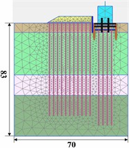
Given the uniform layout of the existing embankment fill and pile foundations in the direction perpendicular to the Shanghai-Tong high-speed railway, along with their consistent cross-sectional geometry, stress conditions, and loading mechanisms, the system is simplified into a 2D plane strain problem in PLAXIS. The most critical scenario is selected for numerical simulation. For ease of analysis, a Cartesian coordinate system is adopted, with the borehole location set as the origin (0, 0). The model boundaries span from –20 m to 50 m along the -axis and from –100 m to 20 m along the -axis. To enhance calculation accuracy, 15-node triangular elements are used for soil meshing. The groundwater table is set at an elevation of 0 m, and flow is restricted at the model boundaries. The final finite element model consists of 2,835 elements and 25,501 nodes. The mesh layout of the finite element model is illustrated in Fig. 2. The model is validated against field monitoring data, with deviations within 15 %.
Fig. 1Site engineering dimension drawing (m)
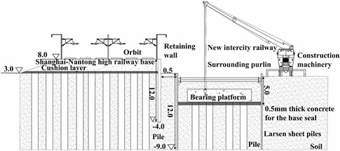
Fig. 2Mesh division of the model
3. Results and analysis
3.1. Subgrade soil displacement
Six monitoring points (A to F) were selected. Horizontal and vertical displacement curves were plotted, as shown in Fig. 3. Displacement diminishes with increasing distance from the excavation.
As shown in Fig. 3, dewatering and excavation during the early construction stages represent a typical unloading process, causing horizontal displacements toward the pit and settlements due to groundwater drawdown reducing pore pressure and increasing effective stress. The maximum horizontal displacement is 9.71 mm and maximum settlement is 9.73 mm, decreasing with distance from the pit. Activation of the support structure and construction of the concrete bedding layer induce slight reverse horizontal displacements in remote sections of the subgrade, mainly due to the lateral expansion force exerted by the transverse bracing system. The greatest displacement increment (3.94 mm) is caused by cofferdam removal, followed by support system and pile activation. All construction stages result in vertical settlement of the subgrade soil, with pier construction and loading most significantly influencing settlement.
Fig. 3Subgrade soil displacement curves
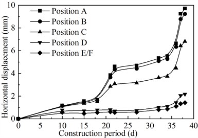
a) Horizontal displacement
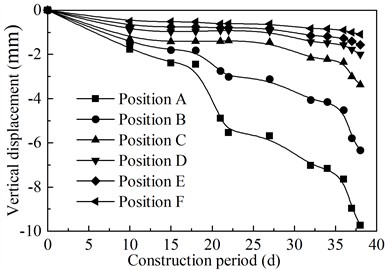
b) Vertical displacement
3.2. Displacement of subgrade pile foundations
The maximum displacement of each pile occurs at its top node. Eleven piles were labeled sequentially from 1 to 11 based on proximity to the excavation pit. Horizontal and vertical displacement curves of the pile tops are shown in Fig. 4.
Fig. 4Displacement curves of pile foundations
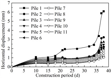
a) Horizontal displacement
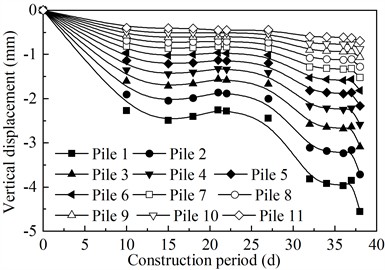
b) Vertical displacement
As shown in Fig. 4, horizontal displacement of the surrounding soil causes lateral deflection and settlement of the piles, decreasing with distance from the pit. Pile 1, closest to the excavation, shows maximum horizontal displacement of 6.08 mm and settlement of 4.56 mm. Sheet pile removal has the greatest impact on pile horizontal displacement, followed by drilling and support system operations. For vertical displacement, drilling and pier column casting have the most pronounced effects.
3.3. Influence of construction distance on subgrade displacement
The distance from the new pier cap to the existing subgrade is denoted as . Keeping all other conditions constant, was varied as follows: 0.25 m, 0.5 m, 1 m, 2 m, 4 m, 6 m, 8 m, 10 m, 12 m, 14 m, 16 m, 18 m, 24 m, 32 m, 48 m, and 64 m. For each case, the maximum horizontal and vertical displacements of the existing subgrade soil were determined. The point of maximum displacement consistently occurred at the highest elevation of the embankment fill. Empirical relationships between displacement (, ) and distance (), as shown in Fig. 5. Both horizontal and vertical displacements clearly decrease with increasing .
The fitting equations derived from the data are as follows:
(1) Horizontal displacement:
where is the horizontal displacement (mm), is the distance from the new pier cap to the existing subgrade (m), and is the coefficient of determination.
(2) Vertical displacement:
where is the vertical displacement (mm), and the other parameters are defined as above.
Fig. 5Displacement-distance fitting curves
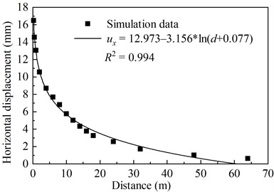
a) Horizontal displacement
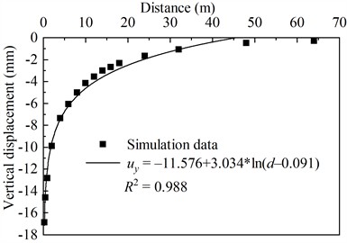
b) Vertical displacement
Current standards [15-16] stipulate allowable settlements of 30-50 mm for ballasted tracks at 300-350 km/h and displacement rates ≤ 3 mm/day for adjacent sections. Given the higher speeds of high-speed rail, stricter control is warranted. Simulation results show that horizontal and vertical displacements are of similar magnitude. Considering both directions, when the construction distance exceeds 60 m, the impact on the existing railway is negligible. At distances of 12-60 m, the influence is minor; at 1.8-12 m, the impact becomes significant; and when within 1.8 m, the effect is substantial. Practically, construction within 1.8 m requires reinforced retaining structures and real-time monitoring; 1.8-12 m needs standard monitoring with sheet pile support; beyond 12 m, routine procedures suffice.
4. Conclusions
This study investigates the impact of pier cap construction on the adjacent subgrade section of an existing high-speed railway in a soft soil area. A site-specific model was developed using the PLAXIS finite element software, and the following conclusions were draw:
1) The HSS model provides more reliable displacement predictions under small-strain conditions than the conventional M-C model, aligning closely with field measurements.
2) Maximum displacement of the subgrade and retaining wall occurs at the upper edge near the excavation, with both horizontal and vertical peak values reaching approximately 14.6 mm. Pile foundation displacements are concentrated within the depth range of the excavation and oriented toward the pit.
3) The most influential construction stages for horizontal displacement include bored pile activation, dewatering excavation, sheet pile removal, and backfilling. For vertical displacement, the most impactful are bored pile activation and pier column casting.
4) Construction within 1.8 m of the existing HSR subgrade induces significant displacement; 1.8-12 m causes noticeable impact; 12-60 m, minor impact; beyond 60 m, the effect is negligible.
References
-
M. Tan, Y. Yang, L. Bian, J. Zhang, and S. Ohno, “Safe operation plan for high-speed rail based on dynamical prediction model of short-term rainfall,” KSCE Journal of Civil Engineering, Vol. 29, No. 4, p. 100058, Apr. 2025, https://doi.org/10.1016/j.kscej.2024.100058
-
H. Zhao et al., “The impact of dissipative algorithms on assessment of high-speed train running safety on railway bridges,” Engineering Structures, Vol. 314, p. 118298, Sep. 2024, https://doi.org/10.1016/j.engstruct.2024.118298
-
T. H. Gong and Y. L. Yao, “Effect of pier bearing construction on nearby high-speed rail line bridges,” Vibroengineering Procedia, Vol. 55, pp. 118–124, Sep. 2024, https://doi.org/10.21595/vp.2024.24145
-
P. Pan, W. Chen, and P. Wu, “Safety and stability analysis of demolition and reconstruction of existing railway bridge piers and caps,” Applied Sciences, Vol. 13, No. 12, p. 7213, Jun. 2023, https://doi.org/10.3390/app13127213
-
Y. Wang, S. Liang, C. Huang, and R. Wang, “Foundation settlement response of existing high-speed railway bridge induced by construction of undercrossing roads,” Sustainability, Vol. 14, No. 14, p. 8700, Jul. 2022, https://doi.org/10.3390/su14148700
-
D. S. Liyanapathirana and R. Nishanthan, “Influence of deep excavation induced ground movements on adjacent piles,” Tunnelling and Underground Space Technology, Vol. 52, pp. 168–181, Feb. 2016, https://doi.org/10.1016/j.tust.2015.11.019
-
M. Shakeel and C. W. W. Ng, “Settlement and load transfer mechanism of a pile group adjacent to a deep excavation in soft clay,” Computers and Geotechnics, Vol. 96, pp. 55–72, Apr. 2018, https://doi.org/10.1016/j.compgeo.2017.10.010
-
M. Zhao et al., “Stability analysis of TBM tunnel undercrossing existing high‐speed railway tunnel: a case study from Yangtaishan Tunnel of Shenzhen Metro Line 6,” Advances in Civil Engineering, Vol. 2021, No. 1, pp. 1–18, Jan. 2021, https://doi.org/10.1155/2021/6674862
-
C. Chen and Z. J. Wang, “Finite element analysis of the influence of foundation pit excavation on railway viaducts in adjacent city (in Chinese),” (in Chinese), Construction and Design for Engineering, Vol. 7, pp. 39–41, 2021, https://doi.org/10.13616/j.cnki.gcjsysj.2021.04.013
-
Z. Yang and X. Wang, “Influence of metro tunnel excavation on deformation of existing pedestrian underpass in changzhou railway station platform,” IEEE Access, Vol. 8, pp. 55860–55871, Jan. 2020, https://doi.org/10.1109/access.2020.2981343
-
D. Lee, “Analysis on the influence and reinforcement effect of adjacent pier structures according to the underpass construction,” Journal of the Korean GEO-environmental Society, Vol. 23, No. 4, pp. 29–39, 2022, https://doi.org/10.14481/jkges.2022.23.4.29
-
F. Rizzo, L. Caracoglia, and G. Piccardo, “Examining wind-induced floor accelerations in an unconventionally shaped, high-rise building for the design of “smart” screen walls,” Journal of Building Engineering, Vol. 43, p. 103115, Nov. 2021, https://doi.org/10.1016/j.jobe.2021.103115
-
T. Ali, M. N. Eldin, and W. Haider, “The effect of soil-structure interaction on the seismic response of structures using machine learning, finite element modeling and ASCE 7-16 methods,” Sensors, Vol. 23, No. 4, p. 2047, Feb. 2023, https://doi.org/10.3390/s23042047
-
Z. Yin, R. Jin, S. Guan, Z. Chen, G. Dai, and W. Zhu, “Research on construction sequencing and deformation control for foundation pit groups,” Applied Sciences, Vol. 15, No. 14, p. 7719, Jul. 2025, https://doi.org/10.3390/app15147719
-
China Railway, “Observation and evaluation specification for settlement deformation of railway engineering: Q/CR 9230-2016.,” China Railway Publishing House, Beijing, 2016.
-
“Technical code for monitoring of building foundation pit engineering: GB 50497-2009,” Ministry of Housing and Urban-Rural Development of China, China Planning Press, Beijing, 2009.
About this article

The authors have not disclosed any funding.
The datasets generated during and/or analyzed during the current study are available from the corresponding author on reasonable request.
The authors declare that they have no conflict of interest.
