Abstract
This article investigated the construction conditions of the pile foundation in the Wuxing section of the “Shanghai Suzhou Huzhou” railway bridge project. To test the reliability of large diameter connectors, it has established a finite element model with ABAQUS software for numerical simulation. Based on on-site tests, the reliability of the connection between the pipe pile and the cover steel was studied. According to the simulation results, when the load is 900 kN, the displacements of A2 and A3 steel pipe piles are 55.8 mm and 60.1 mm, respectively. The load-displacement relationship shows a high-order curve distribution. According to the results of on-site experiments, the displacements are 77.9 mm and 60.2 mm, respectively. The load-displacement relationship is linear. The results for the simulation and on-site testing are consistent. This study provides a basis to the research on the reliability of the connection between large-diameter steel pipe piles.
1. Introduction
In recent years, few studies have focus on the connection method between prestressed high-strength concrete pipe piles (PHC pipe piles) and cap beams. Usually, finite element analysis or numerical simulation is used to numerically analyze the connection, pull-out performance, horizontal bearing capacity, tensile bending, and tensile shear performance between pipe piles and cap beams. Wang Ruifang et al. [1] analyzed the distribution mechanism of soil reaction force at the bottom of PHC pile cap beam using ANSYS program, and derived the working failure behavior of pile group from the soil reaction force at the bottom of cap beam. Zhang Xingyu et al. [2] studied the mechanical properties of PHC pile with added core filling and top embedded steel wire based on experiments, which improved the brittle performance of the pile. Lei Haiyang et al. [3] conducted a series of on-site testing studies on PHC high cap pipe piles used in soft soil areas in practical engineering, and provided the application characteristics of high cap pipe piles in soft soil areas. Dong Fengbao [4] used ABAQUS software to analyze the foundation of high cap pipe piles, clarified the horizontal bearing mechanism of high cap pipe piles, and proposed several measures to improve the horizontal bearing capacity of pile foundations.
Liu Lixia [5] studied the load transfer characteristics and bearing capacity of high-capped pipe piles, analyzed the aging bearing capacity of high-capped pipe piles, the stress behavior and the change law of the bearing capacity under horizontal loads, and obtained some benefits for engineering design. According to the national standard atlas, Xing Keyong et al. [6] carried out horizontal bearing capacity tests on single piles, single piles and caps under joint stress on the spot, and concluded that the inserted ribs in the pipe piles played a very good restraint role. Rong Xian et al. [7] used four PHC pipe pile cap specimens with different improvements to conduct low cycle reciprocating loading tests. Research shows that adding steel fibers to pile concrete can improve the seismic performance of PHC pipe piles. Wang Tiecheng et al. [8] completed the low-period reciprocating load test of six joints between PHC pipe piles and caps, and described the failure process and failure form at the joints. Li Qiang et al. [9] used ABAQUS software to calculate and analyze the combination model of PHC pipe piles and caps, and investigated the mechanical characteristics of the joints between PHC pipe piles and caps under the combined action of axial tension and horizontal loads. It also analyzed the stress of plate-welded anchor bars and mechanical sleeve-connected anchor bars under axial tension.
Theoretical research directions and tools are also constantly evolving. With the advancement of technology, the construction of nodes has undergone significant improvements. In addition, the finite element method of rod structures has also developed into 3D solid finite element method, which can conduct more comprehensive and detailed analysis of various factors [10-13]. In the field of architecture, these advances have had a significant impact on architectural design, construction, and renovation [13-16]. By simulating and analyzing the response of building structures under different conditions, engineers can better evaluate the performance and safety of the structure and take measures to optimize the design and improve the safety of the structure [16-18]. Using advanced finite element analysis software, construction engineers can simulate the response of structures under different earthquake, wind, and temperature to predict the results and optimize their design. These tools also allow engineers to conduct fine-grained analysis of structures to identify and solve problems and ensure the long-term stability and reliability of buildings [19-20].
In summary, with the advances in theoretical research, we will see more improvements in architecture and other fields [21]. These tools will help engineers simulate and analyze the effects of various factors on structures to design safer, reliable, and effective buildings and systems [22-23]. Abutment is a structure for transmitting internal forces and deformations between the upper components of a bridge and the lower foundation. It is a key part of bridge design calculations and a weak link in the transmission of stress and deformation for the entire system. This article starts with details, and the cap steel pile joint section focuses on two key issues: the design calculation of the pile cap steel pile node and the optimization of the structural form of the pile cap steel pile joint section. Numerical simulation and on-site testing are used to study the stress mechanism between the connection and concrete. The data obtained from on-site testing provides more objective and practical engineering insights. They help determine the reasonable joint section connection structure between steel and concrete structures to give the structure a higher bearing capacity.
2. Project overview
The Luhe Bridge project has 57 piers and 921 PHC piles, while the Wuxing section of the Luhe Bridge project has 36 piers and 362 PHC piles. Based on engineering practices and the research of scholars such as Liang [24], Hedley [25], and Ameli [26] on the strength of bridge structures, there are two mainly types of failure for pipe piles. One is the bending and shear failure of the pile itself, and the other is the bending failure of the pile cap connection node. Currently, the application of pipe piles in railway bridge engineering has been explored, but a complete theoretical system has not been formed and needs to be verified through more experiments. To make the substructure of railway bridges more stable, large diameter pipe piles are used for the substructure. Under the action of train braking force, large diameter pipe piles will generate large horizontal forces and bending moments at the connection between the pile cap and the pipe pile. Therefore, bending failure at the connection between the pile and the cap is more likely to occur. The recommended method in the national standard atlas “prestressed concrete pipe piles” (10G409) is to directly weld steel bars on the end plate. When this method is applied to large pipe piles, there are some problems: firstly, the welding seam between the steel bar and the end plate is perpendicular to the direction of the steel bar, which is prone to distortion. Secondly, the on-site welding workload is too large. Thirdly, the quality of on-site welding cannot be guaranteed. Therefore, it is necessary to conduct research and verify the bending resistance measures to connect large-diameter pipe piles with the caps.
Field tests were conducted on the pipe pile head (ratio: 1:1) to understand the failure and stress of the joint between the pipe pile head and the cap and to verify the design parameters and construction technology. It has verified and compared the performance and reliability of different connection methods with the supportive platform.
3. Finite element calculation analysis of the connection between pipe pile and cap
3.1. Basic assumptions
Finite element method (FEM) is adopted in this paper to analyze factors such as the size of the model, the quality of the grid division, the selection of the unit, and the convergence of the nonlinear computation. The paper also uses dynamic/explicit module in the software ABAQUS to quasi-statically simulate the force relationship among the “cap-pipe-pile-soil”. The assumptions used in simulation calculations are as follows:
(1) The vertical deformation at the bottom of the pile is limited. This assumption is in line with the reality. As the vertical bearing capacity of the pile is balanced with the external load, the vertical deformation at the bottom of the pile is small. Transverse bending is the core index to examine the performance of the pile-abutment connection. In addition, there is no vertical counterweight in the test. To reduce the number of units in the simulation, only a single pile with a length of 16m is selected.
(2) Soil scale. Although infinite soil size meets the requirements, the scale of the soil should be limited for the efficiency of calculation. In this paper, the soil dimensions are set to be “length × width × height = 16.55 m × 12.00 m × 15.50 m”. The minimum soil size is 6 ( is the diameter of the pile, 1.0 m).
(3) Soil re-consolidation. After the piles are in place, the soil is re-consolidated. This article ignores the addition of stress to the pile during the piling or after the cap is poured. It assumes that before the test begins, the pile soil is stable and does not sink.
(4) The soil water is saturated. The location of the site is in a small foundation pit, and after rain, there is significant build-up of water. The soil layer in the test had a high moisture content, poor soil quality, and very little bearing capacity. This assumption is reasonable for a given height of the soil layer.
The extracted data can be used as a reference for the stress of the 282 # pipe pile cap of the Suhu Extra Large Bridge Wuxing Bridge section of the Shanghai Suhu Railway Section 2 (Table 1).
Table 1Load internal force combination of pipe piles and cap pile heads on the line
Load condition number | ||||||
(kN) | (kN) | (kN) | (kN.m) | (kN.m) | (kN.m) | |
1 | 3132.8 | 17.7 | 6.6 | 2.8 | 35.5 | 67.7 |
2 | 3221.0 | 41.4 | –226.2 | 7.0 | 402.3 | 99.8 |
3 | 829.3 | –5.5 | 227.8 | 8.3 | –378.6 | 1.3 |
Note: represents the axial force direction, represents the transverse bridge direction, and represents the longitudinal bridge direction | ||||||
3.2. Model establishment
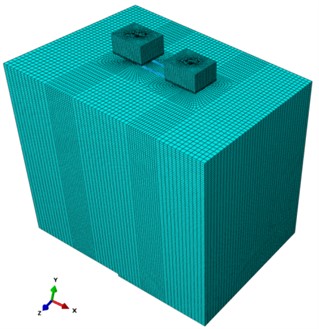
The model conducts test by simulating several key components and connections involved in PHC pile design and construction. These include the placement of PHC pile foundations, prestressed tendons and spiral reinforcement within the pile structure, the connection between PHC piles and core-filling concrete, and the correlation between the spiral steel bars, PHC pipe piles, and the cap. The model also reflects the precise dimensions of the cap platform and the arrangement of the steel cage. To ensure accurate stress and deformation analysis, a grid partitioning approach is utilized. This approach focuses on densely dividing the pile and soil regions of interest, while sparsely dividing the soil regions located farther away from the pile. This approach ensures accurate model calculations while also optimizing computational efficiency. Consequently, a linear gradient grid control is adopted, with a starting grid length of 1 and an ending grid length of 0.5.
To simulate the constraint mode during loading, the side wall of the pipe pile is affixed to a semicircular steel plate ( 10 mm), and six strands of steel wires are wrapped tightly around the plate. Fig. 1 shows how the PHC pipe pile and the cap are connected in the model. A double line elastic-plastic model is used to represent a variety of materials (steel wire not included). Table 2 lists the model's strength and strain parameters.
Table 2Material parameters of steel double line elastic-plastic model
Steel type | Elastic | Plasticity | ||||
Elastic modulus (N/mm2) | Poisson’s ratio | Yield strength (N/mm2) | Plastic Strain | Strength (N/mm2) | Plastic Strain | |
HRB400 | 2.06×10⁵ | 0.3 | 400 | 0 | 600 | 0.09 |
Q235 | 2.06×10⁵ | 0.3 | 235 | 0 | 400 | 0.09 |
Wirerope φ20 | 1.23×10⁵ | 0.3 | 1770 | 0 | / | / |
Prestressed reinforcement | 2.00×10⁵ | 0.3 | 1080 | 0 | 2000 | 0.05 |
Fig. 1Model establishment of connection between PHC pipe pile and cap
In this article, ABAQUS, the non-linear finite element analysis software, is used for simulation. The soil, pipe piles, core-filling concrete, cap, and half-circle steel plate are simulated by C3D8R element type T3D2. The bond between steel bar and concrete comprises three parts: chemical bonding strength, friction resistance, and mechanical interlocking force. The steel wire and the semicircular steel plate are also bounded. Factors for numerical calculation model, including material properties, boundary conditions, loads, and other factors, are pre-defined on separate geometric models.
In the elastic stage, the model uses a linear elastic model to describe the mechanical properties of the material. When calculating, concrete can be regarded as an elastic homogeneous material, and the constitutive relationship can be expressed in tensor form using the generalized Hooke’s law:
where is the material constant, which is a first and fourth order tensor, assuming the material. When it is isotropic, two constants can be used and to express, and . It is called the Lame constant, and represents stress and strain tensors, respectively.
In the plastic stage, the elastic modulus of the damaged CDP model can. The relationship between the damage factor d and the initial non-destructive elastic modulus is expressed as:
where is the initial (non-destructive) elastic modulus; is the damage factor:
where stress state variable; is the uniaxial tensile and compressive damage variable; under uniaxial cyclic loading, and are functions of stiffness recovery stress state related to stress reversal.
3.3. Boundary conditions
The experimental area is the top surface of the soil. To improve simulation accuracy, we constrain its five side surfaces and also constrain the vertical deformation at the bottom of the pile to prevent the pile from sinking during testing. This is consistent with the initial condition that the pipe pile is buried in deep soil and will not sink. Fig. 2 shows the boundary conditions of the model.
Table 3 lists the parameters of the geotechnical report. Four sets of parameters for soil layers were selected to simplify the calculation.
Table 3Material parameters of soil around piles
Name | Length range (m) | Elastic modulus (MPa) | Poisson’s ratio | Internal friction angle (°) | Dilation angle (°) | Cohesive force (kPa) |
Silty silty clay | 2.6 | 3.00 | 0.2 | 12.0 | 0.1 | 10 |
Silty clay | 3.4 | 21.0 | 0.3 | 19.0 | 0.1 | 25 |
Silty silty clay | 7.0 | 18.0 | 0.2 | 16.1 | 0.1 | 20 |
Silty clay | 3.0 | 21.0 | 0.3 | 19.0 | 0.1 | 25 |
Fig. 2Boundary conditions of the model (except for the top surface of the soil, the lateral deformation of the other five surfaces of the soil is restricted)

3.4. Numerical calculation analysis
3.4.1. Initialization of structure
The pile and cap's structural forces must be initialized. Prior to the test, the PHC pipe pile, post-cast cap, and soil must all be in a stable condition. Although the PHC pipe pile is installed in the soil, the pile's concrete and pre-stressed tendons possess initial stress that must be accounted for during the initialization phase. This initial stress cannot be relieved through cooling or other methods in the final test configuration, as such measures would alter the structure's state. Consequently, no pre-stress should be applied to the structure, as this would modify the stress states of the soil, core-filling concrete, and caps.
The calculation is executed in the following sequential steps: (1) Apply vertical pre-stress and gravity to the pile in the soil-less condition. (2) Increase the gravity of the core-filling concrete. (3) Raise the gravity of the cap to observe how the pipe piles are linked to pile caps. (4) Once the deformation state is eliminated as the initial configuration of the structure, solely the stress state is retained. The stress value of the deformation state is integrated into the new structure for further computations.
Fig. 3Initialization of PHC pipe pile (stress is calculated separately; deformation is not included)
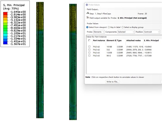
When cap and core-filling concrete are connected, the core-filling concrete plays a key role in reducing the stress on the pile. Fig. 3 shows the minimum principal stress of the pile concrete, which range from –10.9 MPa to –5.60 MPa, in both the non-core-filling concrete area and the core-filling concrete area of the pipe pile.
Fig. 4Stress distribution of PHC pipe pile after initialization
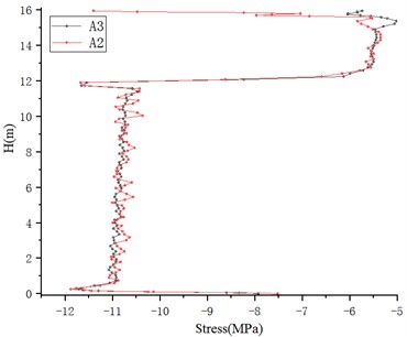
Two columns of units are selected for computation. One is the A3 pipe piles (left) and the other is A2 pipe piles (right). Fig. 4 shows the stress distribution of their units. The pipe pile is 16 meters long. Its coordinate is zero and its height (H) is along the Y direction. Fig. 4 shows the stress distribution of the pile concrete after it is pre-tensioned and prestressed. The gravity of the core-filling concrete and cap is sharply reduced at the 4 m section of the core-filling concrete. The stresses at other sections concentrate at around –11 MPa. When the products leave the factory, the stress level of concrete in the pile must be controlled at a –10 MPa according to the regulation.
The initialization of the soil layer’s ground stress is necessary when excavation and piling are considered. This is to make sure that there is no soil deformation or displacement at the initial state.
The stress under the self-weight of the pipe pile in the restrained state should be calculated. The stress of the soil layer is set as the initial value and substituted into the subsequent model for further calculation (Fig. 5 and Fig. 6).
After the initialization of the structure, a horizontal load is exerted to examine the mechanical performance of the pile and the components under different pile-cap connection modes.
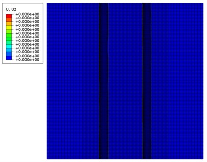
Fig. 5Stress distribution diagram after soil layer initialization
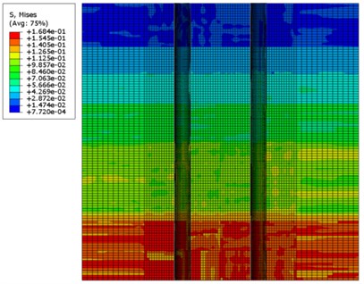
Fig. 6Displacement distribution diagram after soil layer initialization
3.4.2. Output of the platform displacement
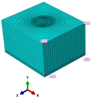
To track the platform’s displacement, four corner points on the loading surface were selected. As shown in Fig. 7, the 4 points are defined as A2G, A6G, A4G, A8G for the cap loading surface that is connected to the A3 pile and as A1G, A5G, A3G, A7G for the cap loading surface that is connected to the A2 pile. These numbers match the monitoring points that were set up during the field test.
Fig. 7Layout of A3 pipe pile-cap displacement monitoring points
According to Fig. 7 and the calculation results, there is a small displacement at the bottom of the loading surface. When the load increases, the displacement at the top will slightly increase. When the load 900 kN, the displacement of A3 pile cap’s upper edge is 60.1 mm, which is 4.3 mm higher than that of the A2 pile cap. When the loaded increases to 1000 kN, the displacement of the A3 pile cap’s upper edge becomes 76.2 mm. For the A3 pile cap alone, the displacement of the upper edge is 13 mm greater than that of its lower edge at the load level of 900 kN. The displacement of A2 pile cap’s upper edge is 8.8 mm greater than that of the lower edge.
4. Reliability test of the connection between pipe pile and cap platform
4.1. Experimental design
The special conditions of the site make it inconvenient to build a reaction platform between piles. To ensure the stability of the applied load, the “back-to-back mutual push” method was selected for testing during the construction of the cap platform.
(1) The connection with the pile head: a connecting steel bar is welded on the end plate of the A2 pipe pile. The sleeve is pre-buried under the end plate of the A3 pipe pile while the pipe pile is prefabricated. Then, the pipe pile is put into sleeve socket to connect with the steel bar.
(2) The arrangement of measuring points: a strain gauge is a sensor whose resistance varies with applied force. It converts force into a change in electrical resistance which can then be measured. In this paper, the measuring points were aligned and strain gauges were installed at steel bars, pile cap concrete, and the caps, respectively.
(3) Technology to build the cap: the formwork for the cap and binding of steel bars of A2 and A3 pipe piles are carried out based on the drawings. A cap is cast on each pile and the concrete is given sufficient curing time. For ease of observation and the placement of monitoring points, the pile is moved out of the soil layer to a specific depth based on its actual circumstances. The platform is 2.5 m×2.2 m×1.5 m in size and 30-60 cm above the ground.
(4) Start the test: At the beginning of the test, a double-controlled jack is built between the end faces of the cap of A2 and the cap of A3, and the loading method adopts horizontal mutual push.
(5) Test data collection: sensors are buried or temporarily installed in the equipment. After they are connected and the load is exerted, various test data are collected simultaneously.
Fig. 8Load-applying device system for field testing
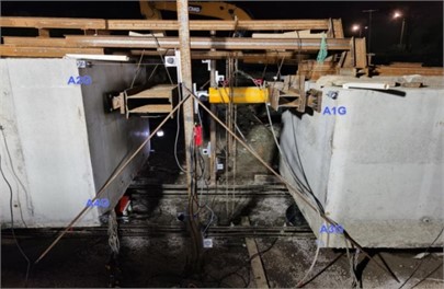
In this test, horizontal thrust is loaded to the pile from one side and for multiple cycles. To evaluate the reliability of the connection point, loads are applied until the pipe pile-cap connection is damaged or other damages occur. This is to examine the maximum horizontal thrust allowed for loading (see Fig. 8).
4.2. Detection and analysis of displacement
As the jacking loads change, the soils around pile are squeezed and lateral displacement occurs. The cap platform deforms laterally due to the jack's thrust. The four corner points' displacement values will change with the thrust force. According to the data from the sensor, the displacement under repeated loading does not return to the original zero value, and there is a residual displacement. Figs. 9-12 show the load-displacement curve (-) and load-displacement residual curve on the A2 and A3 pipe pile-cap loading surfaces. After quadratic polynomial fitting, the dotted lines denote the displacement of each measuring point.
Fig. 9Load-displacement curve (P-Δx) of pile platform A2
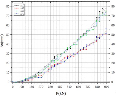
Fig. 10Load-residual displacement curve (P-Δx residual) of pile platform A2
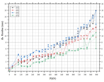
Fig. 11Load-displacement curve of A3 pipe pile-capacity (P-Δx)
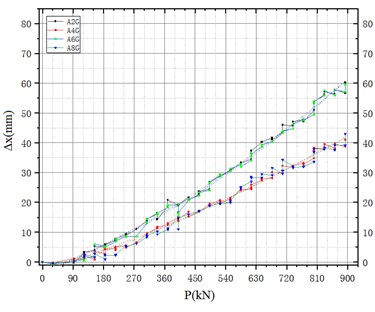
Fig. 12Load-residual displacement curve of A3 pipe pile-capacity (P-Δx residual)
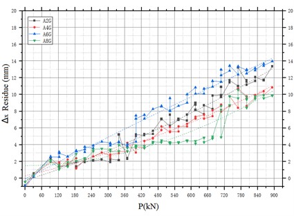
When the load of approximately 900 kN is applied to the A2 “pile cap”, the lateral displacement of the top pushing surface reaches its maximum value of 77.9 mm, occurring in the upper right corner of the thrust surface. Under different experimental conditions, the displacements of the upper left and upper right corners are similar but not identical to those of the lower left and lower right corners. Similarly, when the load of approximately 900 kN is applied to the A3 “pipe pile cap”, the lateral displacement of the top pushing surface reaches its maximum value of 60.2 mm, also occurring in the upper right corner of the thrust surface. Again, due to different experimental conditions, the displacements of the top left and top right corners are similar but not exactly equal to those of the bottom left and bottom right corners.
The reason for the asymmetry of displacement between the bottom left and bottom right corners is that the existing experimental conditions cannot achieve exactly the same situation. However, during the experiment, the displacement values of the top left and top right corners are similar, and the experimental data results are also within an acceptable range. Therefore, this deviation from the perfect symmetry is allowed.
5. Conclusions
1) The connection method that directly puts steel bars in the sleeve on the end plate of A3 pipe pile can consistently transmit the force as the joint force of the “pipe pile-cap” structure. In contrast, the connection method that directly welds steel bars on the end plate of A2 pipe pile shows local characteristics and dispersed force transmission. At 900 kN, the A2 “pipe pile-cap” connection method is almost a plastic hinge, while the A3 “pipe pile-cap” connection method deforms plastically in some units, but the entire section remains as a hinge.
2) The displacement indicators show the changes of the cap pushing surface and the pile. At 900 kN, the lateral displacement of the platform pushing surface reaches its peak. For, the peak of A2 “pipe pile-cap” structure and A3 “pipe pile-cap” structure are fxmax= 77.9 mm and fxmax= 60.2 mm, respectively, both occurring at the upper right corner of the pushing surface. Meanwhile, the peak displacements of the A2 and A3 piles in the soil layer are fxmax= 45.5 mm and fxmax= 35.7 mm, respectively.
3) In theory, when the applied load is 900 kN, the displacement of the A2 and A3 “pipe pile-cap” structures are 55.8 mm and 60.1 mm, respectively. The load-displacement relationship follows a high-order curve distribution. According to the results of on-site experiments, the displacement values were 77.9 mm and 60.2 mm, respectively. The load-displacement relationship appears to be linear.
4) The joint of the cap- pile structure is an important but weak link. It transmits the stress and deformation to the entire system. This paper mainly focuses on the design and optimization of the joint section of the pile-cap structure. Numerical simulation and on-site testing methods are used to study the stress distributed at the connection and the concrete. The data obtained from on-site testing provides objective and practical engineering insights to help designers create better structure with higher bearing capacity to connect the steel and the concrete. It also provides a theoretical basis for other similar engineering projects.
5) This article studies the mechanism of pile-cap connection in large bridges. In the future, the mechanical performance differences between single-hole PBL connectors and group-hole PBL connectors, as well as issues such as aperture, hole spacing and steel plate thickness should be studied. Whether to install through steel bars is another important topic to explore for the design of seamless bridges.
References
-
R. F. Wang and J. H. Pi, “Research on subsoil reaction force of PHC pipe pile cap,” Shanxi Architecture, Vol. 17, pp. 59–60, 2005, https://doi.org/10.3969/j.issn.1009-6825.2005.17.038.s
-
X. Y. Zhang, B. K. Liu, and Y. X. Ling, “Experimental study on shear capacity of connections between prestressed concrete pipe pile and pile cap,” Building Structures, Vol. 4, pp. 11–14, 2008.
-
H. Y. Lei, W. C. Zhang, and P. Y. L., “Experimental analysis of soil squeezing effect of high-capacity pipe piles in soft soil areas,” Chinese Journal of Geotechnical Engineering, Vol. 33, pp. 478–482, 2011.
-
F. B. Dong, “Numerical analysis of horizontal bearing mechanism of high-capacity pipe pile group,” Tianjin University, 2012.
-
L. X. Liu, “Research on load transfer characteristics and bearing capacity of high-capacity pipe piles,” Tianjin University, 2012.
-
K. Y. Xing, C. X. Zhao, and H. Y. Zhao, “Experimental study on the connection performance of prestressed pipe piles and caps,” National Defense Transportation Engineering and Technology, Vol. 10, No. 5, pp. 22–6, 2012, https://doi.org/10.3969/j.issn.1672-3953.2012.05.009
-
X. Rong, P. Lin, and Y. Y. Li, “Experimental study on the seismic performance of improved PHC pipe pile cap,” Concrete and Cement Products, Vol. 11, pp. 29–32, 2013, https://doi.org/10.3969/j.issn.1000-4637.2013.11.007
-
T. C. Wang, Z. J. Yang, and H. L. Zhao, “Experimental study on the seismic performance of the connection nodes between prestressed concrete pipe piles and caps,” Transactions of the Chinese Society of Geotechnical Engineering, Vol. 35, pp. 1002–6, 2013.
-
Q. Li, “Simulation analysis of the influence of tension and bending load-bearing performance of the connection node between PHC pipe pile and cap platform,” Taiyuan University of Technology, 2020.
-
C. F. Huang, “Experimental study on the mechanical properties of the connection between large-diameter PHC pipe piles and caps on high-speed railway bridges,” Railway Construction, Vol. 62, No. 9, pp. 97–102, 2022.
-
T. L. Yan, J. F. Gao, and R. H. Zhang, “Research on the pull-out performance of PHC pipe pile joints and cap connections,” China Construction Industry Press, Soil Mechanics and Geotechnical Engineering Branch of China Civil Engineering Society, 2021.
-
Z. Q. Liu, “Finite element analysis study on the pull-out load-bearing performance of PHC pipe pile hoop type and mechanical meshing pile-pile connection joints,” Taiyuan University of Technology, 2021.
-
M. Y. Mo, “Analysis of the horizontal bearing capacity of the connection nodes between PHC pipe piles and caps under different node structures,” Taiyuan University of Technology, 2019.
-
Y. Xu, Z. Zeng, Z. Wang, and J. Ge, “Experimental studies of embedment length of precast bridge pier with socket connection to pile cap,” Engineering Structures, Vol. 233, p. 111906, Apr. 2021, https://doi.org/10.1016/j.engstruct.2021.111906
-
J. Ge, L. Lai, S. Liu, and X. Yan, “Ultimate bearing capacity analysis of pile caps with new socket connections,” Buildings, Vol. 12, No. 11, p. 2034, Nov. 2022, https://doi.org/10.3390/buildings12112034
-
Y. Wang, K. Wan, H. Xiang, and J. Wang, “Analysis and experimental study on mechanical properties of large-diameter grouted sleeve connections,” International Journal of Geomechanics, Vol. 23, No. 6, p. 04023, Jun. 2023, https://doi.org/10.1061/ijgnai.gmeng-8430
-
G. Zhang, Q. Han, K. Xu, X. Du, and W. He, “Experimental investigation of seismic behavior of UHPC-filled socket precast bridge column-foundation connection with shear keys,” Engineering Structures, Vol. 228, p. 111527, Feb. 2021, https://doi.org/10.1016/j.engstruct.2020.111527
-
C. Liu, Z. Zhang, and R. A. Regueiro, “Pile and pile group response to tunnelling using a large diameter slurry shield – Case study in Shanghai,” Computers and Geotechnics, Vol. 59, pp. 21–43, Jun. 2014, https://doi.org/10.1016/j.compgeo.2014.03.006
-
H. Wang et al., “On-site full-scale load test and reliability evaluation of prefabricated bridge substructure for “pile-column integration”,” Applied Sciences, Vol. 12, No. 11, p. 5520, May 2022, https://doi.org/10.3390/app12115520
-
R. Wang, B. Ma, and X. Chen, “Seismic performance of pre-fabricated segmental bridge piers with grouted splice sleeve connections,” Engineering Structures, Vol. 229, p. 111668, Feb. 2021, https://doi.org/10.1016/j.engstruct.2020.111668
-
Y. Yang, B. W. Melville, G. H. Macky, and A. Y. Shamseldin, “Experimental study on local scour at complex bridge pier under combined waves and current,” Coastal Engineering, Vol. 160, p. 103730, Sep. 2020, https://doi.org/10.1016/j.coastaleng.2020.103730
-
J. Geng, F. Wang, C. Liu, J. Wang, and Z. Zhao, “Parametric study on seismic performance of prefabricated bridge piers connected by ultra‐high performance concrete grout,” Structural Concrete, Vol. 23, No. 3, pp. 1469–1491, May 2022, https://doi.org/10.1002/suco.202100179
-
J. Wu, J. Zhao, Z. Tan, X. Liu, X. Wang, and M. Liu, “Mechanical behavior of large-diameter adjacent shield tunnelling bridge piles: A case study of Chunfeng tunnel,” Applied Sciences, Vol. 12, No. 11, p. 5418, May 2022, https://doi.org/10.3390/app12115418
-
F. Liang, C. Wang, and X. B. Yu, “Performance of existing methods for estimation and mitigation of local scour around bridges: case studies,” Journal of Performance of Constructed Facilities, Vol. 33, No. 6, p. 04019, Dec. 2019, https://doi.org/10.1061/(asce)cf.1943-5509.0001329
-
A. E. Haiderali and G. Madabhushi, “Evaluation of curve fitting techniques in deriving p-y curves for laterally loaded piles,” Geotechnical and Geological Engineering, Vol. 34, No. 5, pp. 1453–1473, Jul. 2016, https://doi.org/10.1007/s10706-016-0054-2
-
M. J. Ameli and C. P. Pantelides, “Seismic analysis of precast concrete bridge columns connected with grouted splice sleeve connectors,” Journal of Structural Engineering, Vol. 143, No. 2, p. 04016, Feb. 2017, https://doi.org/10.1061/(asce)st.1943-541x.0001678
About this article

The authors have not disclosed any funding.
The datasets generated during and/or analyzed during the current study are available from the corresponding author on reasonable request.
Hongmei Ni: conceptualization, formal analysis, methodology, writing-original draft preparation. Xupeng Yin: formal analysis, methodology, writing-review and editing.
The authors declare that they have no conflict of interest.
