Abstract
This paper presents an inertia channel design methodology for a hydraulic damper dedicated to high-speed rail applications. By theoretically analyzing how dimensional parameters of the inertia channel influence the damping force of the hydraulic mount, the calculation methods for both friction losses and local losses are elaborated in detail. Integrating specific design targets, the required inertia-channel dimensions are derived. The study demonstrates that the proposed approach can markedly accelerate the design process of hydraulic dampers and substantially cut research-and-development costs.
1. Introduction
With the rapid development of high-speed railways, train operating speeds continue to rise, and the demands on vibration and noise control have become increasingly stringent [1]. As a key component of the floor vibration-isolation system in high-speed trains, the hydraulic damper’s performance directly affects running stability and passenger comfort. Hydraulic mounts can effectively absorb and isolate vibration, and the dimensional parameters of the inertia channel are a decisive factor in this isolation capability. Traditional inertia-channel design has typically relied on empirical rules, leading to repeated trial-and-error validation during subsequent manufacturing and thus driving up both development cost and lead-time. To avoid the cost penalties of repeated tool modifications, this paper proposes a method for accurately sizing the inertia channel during the conceptual-design phase.
Adjacent to the rubber elastomer is a fluid-filled chamber, typically separated from the main elastomer volume by a flexible diaphragm or a moving plate. This chamber is connected to the main elastomer volume through an inertia track or a series of orifices. When high-frequency vibrations are applied to the mount, the moving mass (such as a decoupler) within the mount starts to oscillate. As it moves, it displaces the fluid in the chamber. The fluid, being incompressible, has to flow through the inertia track or orifices. The flow of the fluid is restricted by the geometry of these passages, which creates a pressure drop across them. According to the principles of fluid mechanics, the pressure drop is proportional to the square of the fluid flow rate. This pressure drop generates a damping force that opposes the motion of the moving mass, thereby dissipating the vibrational energy as heat. The inertia of the fluid flowing through the track also contributes to the overall damping effect, as it resists changes in the flow rate, especially at higher frequencies.
One of the most significant advantages of hydraulic mounts is their ability to provide frequency - dependent damping. At low frequencies, the fluid flow through the inertia track or orifices is relatively unrestricted, allowing the rubber elastomer to dominate the damping behavior. This results in a soft mount characteristic, which is beneficial for isolating large-amplitude, low-frequency vibrations, such as those during engine idling. As the frequency of the vibrations increases, the fluid flow becomes more restricted due to the inertia and viscous effects in the passages. The damping force generated by the fluid flow increases significantly, effectively stiffening the mount at high frequencies. This frequency – dependent behavior allows hydraulic mounts to simultaneously isolate low-frequency vibrations and attenuate high-frequency noise, providing a more balanced and effective vibration isolation solution compared to traditional mounts. Manufacturers can further optimize the performance of hydraulic mounts by adjusting the geometry of the inertia track, the size and number of orifices, and the properties of the fluid to meet specific vehicle requirements.
The inertia track of a hydraulic mount is the key organ that turns low-frequency, large-amplitude vibration into significant damping. Its working excitation is essentially a pressure-difference pulse generated across the upper and lower fluid chambers when the rubber main spring is stroked. During engine idling or road-induced bounce the piston-like motion of the spring compresses one chamber and expands the other; the instantaneous pressure unbalance forces a liquid column to accelerate through the long, narrow inertia track. Because the mass of this liquid column is orders of magnitude larger than the mass that would move through a simple orifice, the resulting inertial resistance produces a reactive force 180° out-of-phase with the input displacement. The periodic reversal of flow converts kinetic energy into heat through entrance/exit losses and wall friction, giving the mount a tunable “liquid mass damper” characteristic that can reach loss factors above 0.5 in the 8-25 Hz band most critical to shake and boom.
The hydraulic damper addressed in this paper is required to carry a static load of 30 kg. To achieve effective vibration isolation above 20 Hz, the natural frequency of the hydraulic isolation system is set at 14.14 Hz. In order to suppress the resonance peak, the hydraulic mount must supply sufficient damping force, which is calculated as follows [2]:
where, is the damping force, is the damping ratio, is the load mass, is the natural angular frequency, is the vibration amplitude.
When the damping ratio is 0.3 and the vibration amplitude is 0.5 mm, the damping force that the hydraulic mount must deliver at the resonance frequency equals 71.1 N. The objective of this paper is to design an inertia channel capable of providing exactly this 71.1 N of damping force.
2. Methods
2.1. Fluid-flow regime
By calculating the Reynolds number, engineers can predict whether fluid flow is laminar or turbulent, thereby guiding the selection of pipe diameter, material, and surface treatment to optimize fluid transportation. This dimensionless parameter, which represents the ratio of inertial to viscous forces, enables engineers to determine appropriate pipeline specifications for desired flow characteristics. This principle is directly applicable to designing inertial tracks for automotive hydraulic mounts, where precise control of flow regime is essential. By optimizing channel geometry and surface properties based on Reynolds number analysis, engineers can ensure optimal damping performance, effective vibration isolation, and reliable operation across varying driving conditions.
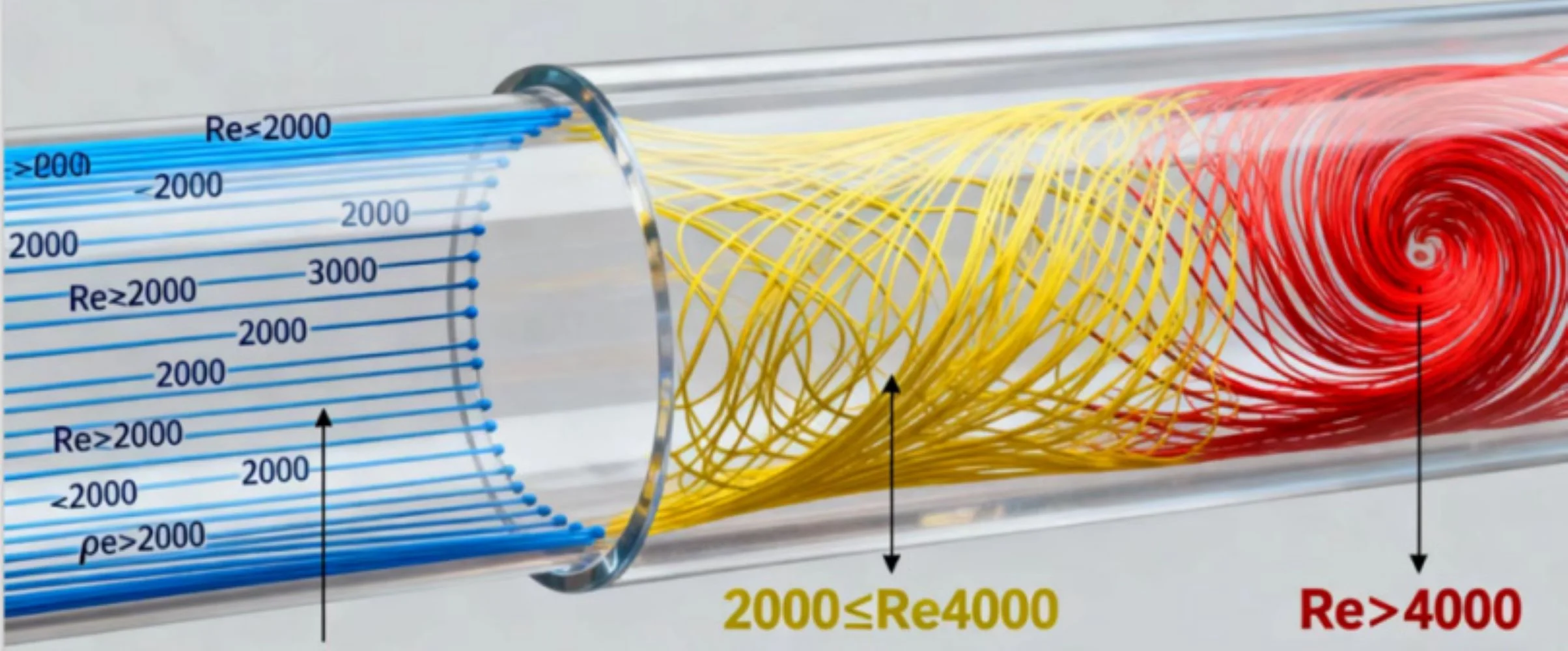
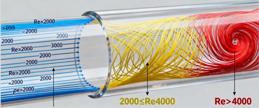
The hydraulic mount is filled with hydraulic oil. At the resonance frequency the required damping force is generated primarily by the flow losses that occur as the oil passes through the inertia channel. Depending on the Reynolds number, the flow regime can be either laminar or turbulent: 2000 corresponds to laminar flow, whereas 4000 indicates turbulent flow [3-4]. Inside narrow channels subjected to high-frequency oscillations, the liquid typically operates in the turbulent regime, the flow state of the liquid is shown in Fig. 1:
where, is the Reynolds number, is the fluid velocity, is the internal diameter of the flow channel, is the kinematic viscosity of the fluid.
Fig. 1The flow state of a liquid
2.2. Types of fluid loss
2.2.1. Frictional loss along the channel
Frictional loss, also called major loss, is the continuous mechanical-energy dissipation that occurs when a real (viscous) fluid moves through a long, straight, uniform conduit of either circular or non-circular cross-section. The root cause is the no-slip condition at the wall, which imposes a velocity gradient across the entire flow area. In laminar flow this gradient is smooth and parabolic; in turbulent flow it is steep near the wall and nearly flat in the core, but in both regimes the shearing of adjacent fluid layers generates internal friction. Work must therefore be supplied by the flow itself to maintain motion, and the corresponding energy is converted irreversibly into thermal energy, producing a pressure drop that increases linearly with distance. Frictional loss is the mechanical-energy dissipation that occurs when fluid flows through a long, straight pipe of constant diameter; it arises from the combined action of fluid viscosity and wall friction and manifests as a pressure drop or head loss. It constitutes one of the principal components of energy loss in any piping system. The frictional loss is calculated as follows [5-6]:
where, is the major head loss, is the Darcy friction factor, is the pipe length, is the fluid velocity, is the gravitational acceleration, is the internal diameter of the flow channel:
where, is the absolute roughness of the flow channel.
2.2.2. Local loss
Local loss, often referred to as minor loss in the context of internal flow systems, is the irreversible conversion of mechanical energy into thermal energy that occurs whenever a fluid stream encounters a discrete, localized geometric disturbance within a piping or ducting network. These disturbances include, but are not limited to, valves, elbows, tees, reducers, expanders, branch connections, inlets, outlets, orifices, and flow-metering devices. Unlike the continuous shear-driven dissipation that characterizes friction along straight, uniform conduits, local losses arise from concentrated, three-dimensional phenomena: sudden deformation of the velocity profile, adverse pressure gradients that trigger boundary-layer separation, recirculation zones with intense turbulent mixing, vortex shedding, and secondary flows. The kinetic energy contained in the coherent, bulk motion of the fluid is progressively cascaded to smaller eddies and ultimately converted to random molecular motion through viscous action. Although each individual fitting may contribute only a modest increment of head loss, hence the traditional label minor. The cumulative effect of numerous elements in a compact system can outweigh the frictional loss accumulated over many metres of straight pipe. Consequently, accurate estimation and minimization of local losses are central tasks in the design of energy-efficient pumping circuits, HVAC distribution networks, hydraulic power plants, and micro-fluidic devices.
Local loss is the additional mechanical-energy dissipation that occurs when fluid passes through localized pipe elements such as valves, bends, tees, sudden expansions, sudden contractions, inlets, and outlets. These elements cause abrupt changes in flow velocity, direction, or profile, leading to flow separation, vortex formation, and intensified turbulence [7-8]:
where, is the minor head loss, is the local resistance coefficient, is the gravitational acceleration.
2.2.3. Total loss and flow resistance
Total loss is the irreversible conversion of mechanical energy into heat within a flowing fluid, expressed as the drop in total head between two cross-sections of a conduit or streamtube. It is the sum of all continuous (major) losses caused by wall friction in fully developed flow and all local (minor) losses generated at bends, valves, sudden expansions, contractions, or any other geometric or surface disruption. The loss is quantified dimensionally as energy dissipated per unit weight of fluid and carries units of length, so it is conveniently reported in meters or feet of fluid column. Engineers use the Darcy-Weisbach equation for straight pipes and experimentally derived loss coefficients for fittings, then add the contributions to obtain the system’s total loss. This value fixes the extra pressure or elevation a pump must supply, governs cavitation risk, and dictates whether the residual head at the outlet meets process or environmental requirements.
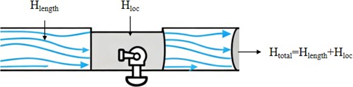
The total loss is equal to the sum of the frictional (major) loss and the minor (local) loss, as expressed by the following formula, as shown in Fig. 2:
where, is the total head loss. And:
where, is the flow resistance, is the fluid density, is the gravitational acceleration, is the piston area.
Fig. 2Definition of total loss
3. Results
To facilitate subsequent machining, the inertia channel of this hydraulic damper is given a rectangular cross-section. Subject to the overall dimensional constraints of the damper, the channel length is set at 165 mm and the piston-end cap area at 988 mm2. The hydraulic oil has a density of 1.1E×10⁻6 kg/mm3 and a kinematic viscosity of 3 mm2/s.
Table 1Damping force calculations under different inertial channel size parameters
Inertia-channel cross-sectional dimensions | Total Loss / mm | Resistance / N | |
Width / mm | Height / mm | ||
1.0 | 1.0 | 287263.9325 | 3121.984418 |
1.2 | 1.2 | 118106.0336 | 1283.576373 |
1.5 | 1.5 | 40428.43351 | 439.3762153 |
1.8 | 1.8 | 17040.64845 | 185.1977673 |
2.0 | 2.0 | 10390.23688 | 112.9210944 |
2.2 | 2.2 | 6659.018537 | 72.37021346 |
2.5 | 2.5 | 3680.176016 | 39.99615295 |
3.0 | 3.0 | 1590.32462 | 17.28364797 |
Using the above data together with the loss-equations derived in Section 3, the damping force that the inertia channel can deliver was computed for several cross-sectional areas; the results are listed in Table 1.
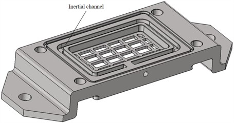
Based on the above calculations, a rectangular inertia channel 2.2 mm wide × 2.2 mm high yields a flow resistance that best matches the required value. Consequently, the final dimensions of the inertia channel for this hydraulic damper are set to 165 mm in length with a 2.2 mm × 2.2 mm cross-section, fully satisfying the design target. This is essentially consistent with the existing hydraulic damper’s inertial-channel dimensions, which’s width is 2.4 mm and height is 2.4 mm. The damper has already been validated through multiple tests and is a mature product. Its inertial-channel dimensions are shown in Fig. 3.
Fig. 3The inertial channel of the existing hydraulic damper
4. Conclusions
This paper presents a systematic and theoretically grounded methodology for accurately sizing the inertia channel of a hydraulic damper specifically engineered for high-speed rail applications. The inertia channel, a critical internal component of hydraulic mounts, plays a pivotal role in determining the dynamic characteristics and vibration isolation performance of the damper. By establishing a clear theoretical relationship between the geometric parameters of the inertia channel – such as its length, cross-sectional area, and shape—and the resulting dynamic stiffness and damping properties of the hydraulic mount, the proposed approach enables engineers to directly determine the optimal channel dimensions during the initial concept design phase. This eliminates the need for time-consuming and costly iterative prototyping and re-machining processes traditionally associated with hydraulic damper development. The methodology integrates specific design targets, including desired natural frequencies, damping ratios, and isolation performance metrics, directly into the sizing process, ensuring that the resulting inertia-channel geometry meets the stringent performance requirements of high-speed rail applications. Furthermore, the theoretical framework developed in this study provides valuable insights into the underlying physical mechanisms governing the dynamic behavior of hydraulic dampers, enhancing the overall understanding of their performance characteristics. Future research efforts can build upon this foundational work by extending the proposed methodology to investigate the influence of varying oil properties – such as viscosity, density, and temperature-dependent characteristics – on the optimal inertia-channel dimensions. Additionally, the approach can be adapted to explore the effects of different excitation frequencies and amplitudes, which are critical considerations in the dynamic environment of high-speed rail operations. Another promising avenue for future investigation involves quantifying the impact of alternative cross-sectional shapes for the inertia channel, such as elliptical, rectangular, or more complex geometries, on the vibration isolation performance and damping characteristics of the hydraulic mount. Experimental validation of the theoretically predicted damping forces and dynamic stiffness values will be essential to further strengthen the reliability and accuracy of the proposed model, ultimately providing a more comprehensive, robust, and trustworthy design basis for the development of next-generation high-speed-rail hydraulic dampers.
Due to time constraints, this design method is merely theoretical calculation and has not been verified through experiments. Further verification of this theoretical design method will be conducted through relevant experiments when the opportunity is ripe in the future.
References
-
T. Li, D. Qin, N. Zhou, and W. Zhang, “Step-by-step numerical prediction of aerodynamic noise generated by high speed trains,” Chinese Journal of Mechanical Engineering, Vol. 35, No. 1, p. 28, Apr. 2022, https://doi.org/10.1186/s10033-022-00705-4
-
S. S. Rao, Mechanical Vibrations. Pearson, 2019.
-
“Flow Regimes (Laminar, Transitional, Turbulent) calculation for Mechanical Engineering,” truegeometry.com, Jan. 2024.
-
Reynolds Number and Its Applications. Engineers Guide Book, 2025.
-
R. V. Pethakar, “Design and manufacturing of pipe friction apparatus to investigate major losses in pipe flow,” International Research Journal of Modernization in Engineering, Technology and Science, Vol. 6, No. 6, 2024.
-
K. Zhang et al., “Analysis of flow instability and mechanical energy loss of fluid field in fluid momentum wheel,” Journal of Marine Science and Engineering, Vol. 12, No. 2, p. 331, Feb. 2024, https://doi.org/10.3390/jmse12020331
-
H. Sun, X. Zhu, X. Wang, J. Zhao, S. Hu, and J. Yu, “A Study on a semi-empirical model for the local loss coefficient of small angle contraction pipes,” Journal of Applied Fluid Mechanics, Vol. 18, No. 4, pp. 1446–1458, Jun. 2025, https://doi.org/10.47176/jafm.18.6.3249
-
T. M. Arteaga-Hernández, J. J. Villegas-León, and F. L. Acuña-Izquierdo, “Head losses and experimental loss coefficient in 45° and 90° elbows of PVC pipes with small diameters for single-phase flow and moderate Reynolds numbers,” Preprints, Jun. 2024, https://doi.org/10.20944/preprints202406.0560.v1
About this article

The authors have not disclosed any funding.
The datasets generated during and/or analyzed during the current study are available from the corresponding author on reasonable request.
The authors declare that they have no conflict of interest.
