Abstract
This paper studies a large-span low-pier continuous rigid frame bridge using Midas Civil to model a full-bridge simulation. It assesses two force-adjustment measures during construction: permanent counterweights at side-span cantilever ends and reverse thrusting at mid-span free ends. Monitoring data shows good agreement between measured pier forces/displacements and simulations, proving the feasibility of measures in improving the bridge’s force conditions.
Highlights
- Permanent counterweights at side-span cantilever ends and reverse thrusting at mid-span free end are proposed to improve the force conditions of low-pier continuous rigid-frame bridges.
- A full-bridge finite element model considering four construction schemes (no measures, counterweights only, thrust only, and combined) shows that combined measures most effectively reduce pier internal forces and displacements.
- Field monitoring data agree well with FEM predictions , verifying the feasibility and effectiveness of the combined measures.
1. Introduction
Continuous rigid frame bridges are widely used due to their good load-bearing performance and convenient construction [1]. To make the overall structural force of continuous rigid frame bridges more reasonable, the piers are usually designed to be relatively high during the design process [2]. However, municipal or river-crossing bridges, constrained by geographical conditions, require low piers, increasing loads on the substructure [3]. Therefore, in order to improve its force-bearing capacity and optimize structural performance, this paper will conduct a systematic study and scheme comparison on the force-bearing control measures of low-pier continuous rigid frame bridges.
2. Improvement measures
Low-pier continuous rigid-frame bridges suffer from excessive internal forces in piers and overloading on foundations, while enlarging foundations is costly. Common improvement measures are as follows [4]-[5]: First, adjusting the pier spacing and edge-center-to-span ratio. Second, adjusting the force state of the structure, such as the permanent counterweight at the cantilever end of the side span and the reverse thrusting at the free end of the middle span, etc.
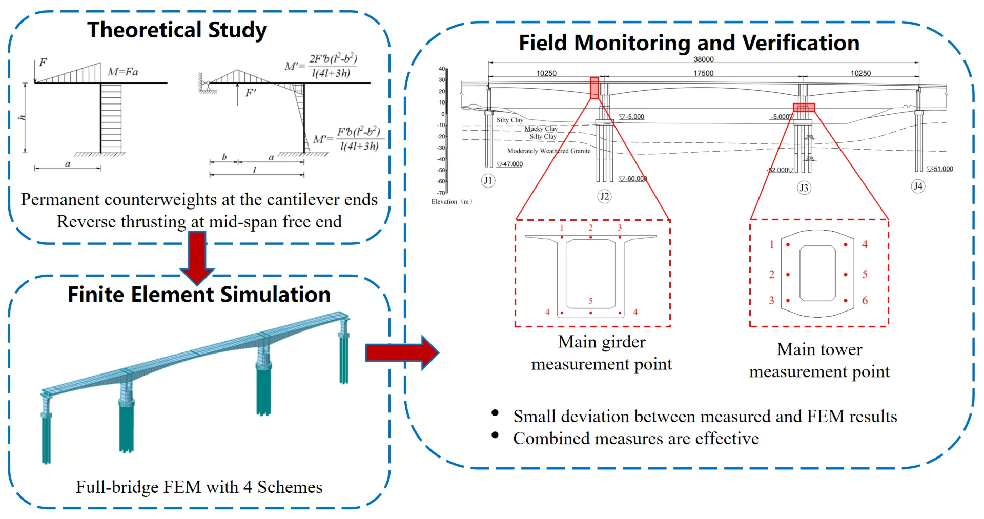
2.1. Permanent counterweights at the cantilever ends of the side spans
The combined cooling load governs the internal forces in the pier body and foundation of continuous rigid-frame bridges. Under the maximum double-cantilever state, the counterweight placed at the end of the side-span cantilever can be partially unloaded after closure. Its load effect is opposite to that of the cooling load, thereby improving the force conditions of the pier body.
Taking the counterweight as the research object, the structural model can be simplified as shown in Fig. 1. Let the counterweight before closure be denoted as , with the corresponding pier bending moment and axial force being respectively. After closure, partial unloading of the counterweight is equivalent to applying a reverse force at the end of the side-span cantilever, generating a reverse bending moment in the pier. This reduces the internal forces in both the pier body and foundation.
Fig. 1Schematic diagram of the force analysis of the permanent counterweight of the side span cantilever
2.2. Reverse thrusting at the free end of the middle span
The cooling load condition controls the force on the pier body and foundation of the continuous rigid frame bridge with low piers. When the temperature drops, the main beam will move as a whole towards the mid-span before the closure, causing horizontal and angular displacements of the main pier top along the mid-span direction [6]. Conversely, applying a top thrust at the mid-span cantilever end generates a bending moment at the pier base, whose effect precisely counteracts that of the cooling load.
3. Calculation examples
3.1. Project overview
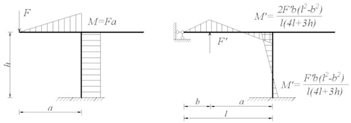
This article takes a 102.5 m+175 m+102.5 m prestressed concrete continuous rigid frame bridge as the research object (Fig. 2). The upper structure is a segmented single-box single-cell box girder, with the girder height changing from 10.4 meters at the root to 3.5 meters at the mid-span according to a quadratic parabola. The bridge deck width is 16.5 meters. The main piers of the lower structure adopt bored cast-in-place pile foundations, with pile diameters ranging from 2.5 meters to 2.3 meters.
Fig. 2Schematic diagram of the bridge type layout of the main bridge (elevation unit: m; rest units: cm)
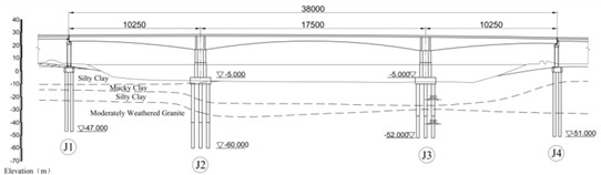
3.2. Finite element model calculation
To evaluate the effectiveness of the proposed construction force adjustment measures in improving the structural behavior of the low-pier continuous rigid-frame bridge, a full-bridge simulation analysis was conducted using Midas Civil to establish the spatial bar system model. The entire bridge structure is simulated as spatial beam units. The model has a total of 745 nodes and 712 units. The superstructure adopts a rigid connection of pier beams, and the vertical displacement simulation is constrained at the support points on both sides. All degrees of freedom of the substructure are constrained at the bottom of the pile, and the m method is used to simulate the boundary of the group pile [7].
Fig. 3Finite element model of the full-bridge simulation calculation
This paper studies the force measures for improving the continuous rigid frame bridge with low piers from the aspect of adjusting the structural force during the construction process. Therefore, under the condition that the design dimensions of the upper and lower structures remain unchanged, four schemes are selected for simulation calculation (Table 1), among which: The permanent counterweight of the side span is to apply a constant load of 715 kN to the side cantilever end of the side span under the maximum double cantilever state; The top thrust is a 4500 kN horizontal top thrust applied to the end of the mid-span cantilever along the edge span direction before the closure, and is unloaded after the closure.
Table 1Corresponding regulatory measures for each scheme
Working condition | Control measures |
Scheme 1 | No horizontal top thrust and permanent side span counterweights |
Scheme 2 | Apply permanent side span counterweights |
Scheme 3 | Apply the horizontal top thrust |
Scheme 4 | Apply horizontal top thrust and permanent counterweight |
Table 2Structural stress conditions of pier bodies and foundations in each scheme
Scheme | Bridge completion | 10-year shrinkage and creep | |||||
(kN) | (kN) | (kN·m) | (kN) | (kN) | (kN·m) | ||
1 | Outer pier top | –68580 | –2860 | –16162 | –65656 | –3763 | –20274 |
Outer pier bottom | –71240 | –2860 | 12438 | –68316 | –3763 | 17359 | |
Inner pier top | –46034 | 587 | 1115 | –48862 | 365 | 643 | |
Inner pier bottom | –48694 | 587 | –4758 | –51522 | 365 | –3008 | |
Pile cap bottom | –136200 | –2272 | –32647 | –163104 | –3398 | –16679 | |
2 | Outer pier top | –72579 | –2900 | –16973 | –68411 | –3799 | –20831 |
Outer pier bottom | –75239 | –2900 | 12029 | –71071 | –3799 | 17161 | |
Inner pier top | –42339 | 623 | –1352 | –46333 | 382 | –893 | |
Inner pier bottom | –44999 | 623 | –5472 | –48993 | 382 | –3424 | |
Pile cap bottom | –163503 | –2278 | –58320 | –163329 | –3417 | –9080 | |
3 | Outer pier top | –68207 | –1446 | –8861 | –65522 | –2837 | –15506 |
Outer pier bottom | –70867 | –1446 | 5601 | –68182 | –2837 | 1268 | |
Inner pier top | –45991 | 1851 | 7513 | –48736 | 1198 | 4851 | |
Inner pier bottom | –48651 | 1851 | –10998 | –51396 | 1198 | –7131 | |
Pile cap bottom | –162783 | 405 | –83171 | –162843 | –1638 | –25043 | |
4 | Outer pier top | –72206 | –1486 | –9426 | –68276 | –2873 | –16063 |
Outer pier bottom | –74866 | –1486 | 5498 | –70936 | –2873 | 12663 | |
Inner pier top | –42296 | 1886 | 7034 | –46207 | 1216 | 4610 | |
Inner pier bottom | –44955 | 1886 | –11429 | –48867 | 1216 | –7547 | |
Pile cap bottom | –163087 | 400 | –79271 | –163069 | –1657 | –22311 | |
3.3. Results and analysis
The internal forces of the pier body and the bottom of the pier cap at the completion stage of the bridge, and after 10 years of shrinkage and creep, are shown in Table 2. The longitudinal displacement of the pier top in the direction of the bridge is shown in Table 3. In Table 2, the signs of axial force, shear force, and bending moment follow the element local coordinate system and the right-hand rule in Midas Civil, with axial force positive in tension and negative in compression.
It can be seen from Table 2 that: (1) Due to the relatively low height of the main piers, the constraints on the deformation of the main girder are strong, and the internal forces of the pier body and the foundation are relatively large, and the difference in axial force between the two sides of the pier is also large; (2) Applying permanent weights at the cantilever end of the side span can effectively reduce the bending moment at the bottom of the abutment; (3) The reverse thrust during the pre-arching before the closure can significantly reduce the shear force and bending moment of the pier body and foundation. (4) By using both measures together, it can effectively reduce the forces on the pier body and foundation, making the structural forces more reasonable.
Table 3Longitudinal bridge displacement at pier top (Unit: mm)
Scheme | 1 | 2 | 3 | 4 | ||||
Outer | Inner | Outer | Inner | Outer | Inner | Outer | Inner | |
Bridge Completion | 6.4 | 4.2 | 1.9 | –0.4 | –15.6 | –17.8 | –20.1 | –22.4 |
10-year Shrinkage and Creep | 25.4 | 22.0 | 20.9 | 17.4 | 3.5 | 0.2 | –1.0 | –4.4 |
Note: “-” indicates the cross-side offset along the edge. “+” indicates offset along the mid-span side | ||||||||
From Table 3, it can be seen that without any construction measures, the top of the pier would shift towards the mid-span side. The maximum shift value was 25.4 mm. With the adoption of construction measures, the displacement of the pier top gradually shifted from the mid-span direction to the side of the abutment, and the shift amount gradually increased from Scheme 2 to Scheme 4. The maximum shift occurred in Scheme 4, which simultaneously adopted the counterweight and jacking construction measures. Considering the 10-year shrinkage and creep, the displacement of the pier top was basically zero. This indicates that the adoption of counterweight and jacking measures can effectively reduce the axial deformation of the main beam caused by shrinkage and creep, reducing the offset of the bridge piers and being beneficial to the overall force distribution of the structure.
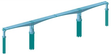
4. Monitoring and verification
4.1. Monitoring contents and methods
To verify the accuracy of the above finite element calculation results and the actual effectiveness of the construction control measures, this study implemented a systematic monitoring plan during the actual bridge construction process. During the construction process, concrete strain gauges were arranged at the pier top, pier bottom, and bottom of the foundation platform to monitor the stress changes at key sections, and the internal forces of the pier were calculated based on the average stress of the sections; a total station monitoring point was set at the pier top to collect longitudinal bridge displacement data in real time. The concrete strain gauges were embedment vibrating-wire type with a resolution of 1 με, paired with a JMZX300 readout unit; the total station was an ES101 model with an angular accuracy of 1″.
4.2. Results comparison
After implementing the permanent counterweight at the side spans and the reverse thrusting at the middle spans (Scheme 4), the monitoring data during the bridge completion stage showed:
The actual trend of the beam axis force variation was basically consistent with the results of the finite element calculation. After applying the thrusting for closure, the beam axis force was –80294 kN, which closely approximates the simulated value of –72206 kN; Regarding the displacement at the pier top: The measured value of the pier top displacement towards the side span during the bridge completion stage was –18.8 mm (for the outer pier) and –21.3 mm (for the inner pier), which was close to the simulated values of –20.1 mm and –22.4 mm.
Fig. 4Measurement point layout

a) Main girder
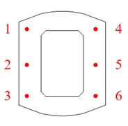
b) Main tower
5. Conclusions
This paper combines finite element simulation with construction monitoring data to verify the control effect of permanent counterweights at the side spans and reverse thrust at the middle spans during the construction stage. Although the long-term shrinkage and creep effects cannot be directly monitored, the long-term analysis based on the verified finite element model indicates that these measures have a significant effect on improving the long-term force-bearing performance of low-arch continuous rigid frame bridges.
References
-
X. Han, W. Li, and P. Li, “Long-term deflection analysis of large-span continuous prestressed concrete rigid-frame bridges based on a refined modeling approach,” Applied Sciences, Vol. 13, No. 17, p. 9727, Aug. 2023, https://doi.org/10.3390/app13179727
-
X. Yan et al., “Seismic response study of super-high pier continuous rigid-frame bridges based on shake table test,” (in Chinese), Earthquake Resistant Engineering and Retrofitting, Vol. 47, No. 2, pp. 115–123, 2025, https://doi.org/10.16226/j.issn.1002-8412.2025.02.014
-
E. Afsar Dizaj, M. R. Salami, and M. M. Kashani, “Nonlinear dynamic behaviour and seismic fragility analysis of irregular multi-span RC bridges,” Structures, Vol. 44, pp. 1730–1750, Oct. 2022, https://doi.org/10.1016/j.istruc.2022.08.112
-
X. Song, H. Melhem, L. Cheng, and Q. Xu, “Optimization of closure jacking forces in multispan concrete rigid-frame bridges,” Journal of Bridge Engineering, Vol. 22, No. 3, p. 04016, Mar. 2017, https://doi.org/10.1061/(asce)be.1943-5592.0001005
-
C. Wang, G. Yang, J. Zhang, J. Wang, and Y. Zheng, “Research on one-time pouring construction technology of side-span cast-in-situ section and closed section,” Applied Sciences, Vol. 14, No. 11, p. 4356, May 2024, https://doi.org/10.3390/app14114356
-
X. S. Liao and T. Liang, “Investigation on closure temperature of long-span pre-stressed concrete continuous rigid-frame bridge,” Applied Mechanics and Materials, Vol. 361-363, pp. 1325–1328, Aug. 2013, https://doi.org/10.4028/www.scientific.net/amm.361-363.1325
-
“JTG D63-2007 Specifications for design of highway bridges and culverts foundation and foundation,” (in Chinese), China Communications Press, Beijing, Ministry of Transport, 2007.
About this article

The authors have not disclosed any funding.
The datasets generated during and/or analyzed during the current study are available from the corresponding author on reasonable request.
The authors declare that they have no conflict of interest.
