Abstract
Based on the structural characteristics of asymmetric vortex compressors, a structure of asymmetric variable diameter base involute vortex comprwessors is proposed, and performance analysis is conducted for vortex compressors used in portable oxygen production systems. According to the normal equidistant method, the volume calculation formula for a variable diameter base circle involute vortex disc with both inner and outer profile angles was derived. An asymmetric variable diameter base circle involute vortex disc model with equal content product ratio was established, and its performance was compared with that of an asymmetric circular involute vortex disc under certain conditions. The results showed that, while ensuring the same compression ratio, the structural size of the model was reduced by 7.58 %, the area utilization rate was reduced by 7.47 %, and the material was more economical. Meanwhile, the gas force was reduced, and the mechanical properties were better. Under the condition of ensuring the same size, the suction volume of the model increased by 8.98 % and the compression ratio increased by 16.3 %, indicating better working performance. This study could provide theoretical reference for the design of vortex compressors in specific scenarios.
1. Introduction
Scroll compressors, recognized as a new generation of positive displacement compressors, are widely employed in the refrigeration and air compression industries due to their advantages such as high efficiency, low noise, and a minimal number of components [1]. With continuous advancements in the design and manufacturing of scroll compressors, their applications have expanded into emerging fields, including refrigeration systems for new energy vehicles and pressurization systems for portable oxygen concentrators. These applications often impose strict spatial constraints, driving the demand for scroll compressors with more compact designs and higher efficiency.
Conventional scroll compressors utilize symmetrically structured fixed and orbiting scrolls and employ symmetrical suction. In such configurations, the outermost wrap segment does not engage in meshing. Furthermore, in systems with only a single intake port, the symmetrical suction mechanism can lead to non-negligible suction losses [2]. In contrast, asymmetric scroll compressors feature a fixed scroll that extends half a wrap beyond the orbiting scroll. This design enables alternating suction processes, which reduces suction losses and improves spatial utilization. The concept of an asymmetric scroll pair was initially introduced by Suefuji [3], who proposed a structure where the fixed scroll wrap was extended by 60°-120° compared to the orbiting scroll. This configuration resulted in a more compact design and reduced the load on the Oldham coupling. Qiao [4] calculated the gas forces and moments in an asymmetric scroll compressor and compared them with those of a symmetric counterpart, demonstrating that the asymmetric design exhibits lower torque, thereby enhancing operational stability and reducing noise. Shaffer [5] applied the control volume method to calculate the areas of the crescent-shaped working chambers in an asymmetric scroll compressor and derived analytical expressions for these areas at various angles. Addressing the issue of significant exhaust pressure loss caused by unequal volume ratios between the two working chambers in asymmetric compressors, Cao [6] proposed an asymmetric dual-arc modification technique. This method equalized the volume ratios in both working chambers, effectively mitigating exhaust losses. Wang [7] developed an asynchronous exhaust scroll compressor by shortening the tooth tip centerline of the orbiting scroll. This innovation ensured equal volume ratios for both working chambers during the exhaust phase in an asymmetric configuration, thereby improving overall performance. Lian [8] proposed an asymmetric variable-clearance scroll profile, which effectively balances chamber pressure distribution and reduces pressure and flow fluctuations.
The fixed and orbiting scrolls constitute the core components of a scroll compressor, and the scroll profile geometry profoundly influences compressor performance. While circular involute is the most commonly adopted profile, there has been a growing interest in variable-wall-thickness designs for scroll profiles to enhance efficiency and reduce size. Tojo K. [9] conducted early feasibility studies on employing a variable diameter base circle involute as a scroll profile. Liu [10] subsequently established the theoretical framework for the variable diameter base circle involute profile and derived equations for its meshing volume. Wang [11] introduced a variable diameter base circle involute scroll structure with a gradually varying meshing clearance, provided the corresponding profile equations, and performed numerical simulations of its working process. Based on the meshing principles of this profile type, Wang [12] determined the range of the unfolding angle for different working chambers and derived volume calculation formulas for each chamber using the normal equidistant method. Ding [13] derived the profile equation for a variable base circle involute that incorporates both inner and outer generating angles, depending on whether the unfolding angle initiates from the x-axis, and investigated the impact of different modification unfolding angles on the compression ratio.
In practical operation, the variable-diameter scroll profile inevitably generates tangential leakage and complex vortex flow inside the working chamber, which directly restricts the compression efficiency and operational stability of the compressor. Huang [14] verified that variable-diameter combined profiles can suppress gas leakage, while radial gap tangential leakage significantly affects internal flow field distribution. Meanwhile, Li [15] demonstrated that multiple flow boundary conditions dominate the vortex evolution characteristics in fluid domains. These fluid dynamic characteristics are non-negligible in the performance analysis of asymmetric variable-diameter scroll profiles.
However, a comprehensive theoretical model for calculating the volumes of variable base circle profiles possessing both inner and outer starting angles remained unaddressed. Scholars have carried out continuous research on geometric modeling, gas force calculation and performance optimization of variable-radius base circle scroll compressors, yet few studies focused on asymmetric equal-volume modified profiles, which is the core innovation of this paper. In addition, recent nonlinear vibration studies on adjustable bio-inspired piezoelectric structures proposed complete nonlinear dynamic analysis frameworks, which can be borrowed to analyze the airflow-induced vibration [16-17].
Building upon the structural characteristics of asymmetric scroll compressors and the variable diameter base circle involute profile, this study designs a novel asymmetric scroll structure based on the variable diameter base circle involute. A complete geometric model is established, and the volume calculation formula for a variable diameter base circle involute scroll featuring both inner and outer unfolding angles is derived. An asymmetric variable diameter base circle involute scroll model with equal volume ratio is subsequently developed. Finally, a comparative analysis of the dynamic performance between the proposed model and a conventional circular involute scroll is conducted. The findings of this study provide a theoretical basis for optimizing scroll compressor design in space-constrained applications.
2. Variable diameter base circle involute scroll profile
2.1. Variable diameter base circle involute
The variable diameter base circle involute differs from the circular involute in that its base circle radius continuously varies during the unfolding process. The radius is defined by the equation , where represents the instantaneous base circle radius, represents the initial base circle radius, represents the base circle radius coefficient, and represents the involute unfolding angle.
Fig. 1Variable diameter base circle involute
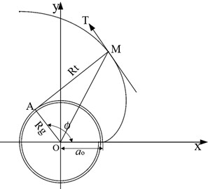
In the figure, point is a point on the involute curve, is its normal line, and is the line perpendicular to this normal. According to the meshing condition of the scroll profile, it can be concluded that:
Therefore, the equation of the variable diameter base circle involute can be expressed as:
2.2. Inner and outer wall profiles of the variable diameter base circle involute
The equations describing the inner and outer wall profiles of the variable diameter base circle involute scroll profile are further categorized into two distinct forms depending on the starting angle at the profile origin [12].
Fig. 2Variable diameter base circle involute scroll profiles with different starting positions
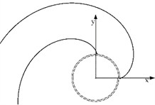
a) Originating from the -axis
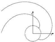
b) Originating below the -axis
When the profile originates from the -axis, the expression for its outer wall profile is given by Eq. (1), while the inner wall profile can be expressed as follows:
When the profile originates below the -axis, it exhibits two symmetrical generating angles relative to the -axis. The expression for the outer wall profile under this condition is as follows:
Similarly, the inner wall profile can be expressed as:
For computational and comparative convenience, this paper adopts the second form, which incorporates generating angles both above and below the -axis. Using the above profile as the fixed scroll, and installing it with a 180° phase difference relative to the orbiting scroll while offsetting by a crank eccentric distance , the profile equation of the orbiting scroll can be derived based on coordinate transformation relationships as follows:
The crank eccentric distance can be calculated as:
Combining Eqs. (2), (7) and (8) yields the profile equations for the outer and inner walls of the orbiting scroll as:
2.3. Volume calculation for the variable diameter base circle involute scroll profile
For the scroll profile originating from the -axis, the volume can be determined using the infinitesimal calculus method. This involves calculating the difference in the areas enclosed by the inner wall of the orbiting scroll and the outer wall of the fixed scroll within a specific interval. The area enclosed by the involute scroll profile of the variable diameter base circle can be calculated as follows:
Fig. 3Area enclosed by the variable diameter base circle involute scroll profile
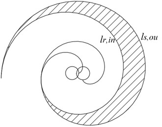
However, the volume calculation theory for variable diameter base circle involute scroll profiles that simultaneously possess both inner and outer generating angles remains underdeveloped. While the calculus method can be applied, it is relatively complex. The author therefore employs the normal equidistant method for this calculation, the fundamental principle of which is illustrated in the figure below.
Fig. 4Schematic diagram of area calculation using the normal equidistant method
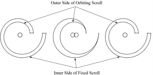
For a closed crescent-shaped cavity, typically formed by the outer wall of the fixed scroll and the inner wall of the orbiting scroll, the normal equidistant method involves shifting one of these profiles by a distance along the line connecting the base circle centers of the two profiles. This transformation changes the crescent-shaped cavity into the form shown in the diagram.
When shifting the outer wall of the fixed scroll, its center baseline can only represent a specific position, allowing the area to be calculated only at that particular angle. Therefore, a more rational approach is to shift the inner wall of the orbiting scroll to the position illustrated in the diagram. In this case, the center baseline can be used to calculate the cavity area at any angle.
The expression for the baseline is as follows:
The arc length of the baseline is:
When the fixed and orbiting scrolls are engaged, and the unfolding angle at the meshing point of the inner wall of the fixed scroll is , the axial projection area of the closed crescent-shaped cavity is:
This formula can be used to determine the axial projection area of the crescent-shaped working chamber at any engagement unfolding angle. Consequently, the corresponding volume is:
The volume ratio can then be calculated as:
where and represent the suction volume and the volume at the exhaust timing, respectively.
2.4. Modeling of the asymmetric variable diameter base circle involute scroll
To facilitate subsequent calculations and comparisons, this study adopts the profile type that simultaneously includes both inner and outer wall unfolding angles. The main parameters of the asymmetric variable diameter base circle involute scroll are listed in Table 1.
Table 1Main parameters of the asymmetric variable diameter base circle involute scroll
Parameter | Symbol | Value | Unit |
Initial base circle radius | 2.62606 | mm | |
Generating angle | 43.636 | deg | |
Base circle radius variation coefficient | –0.02 | – | |
Scroll wrap height | 33 | mm | |
Eccentric distance | 4.27623 | mm | |
Number of fixed/orbiting scroll turns | 2.75/2.25 | – |
Furthermore, due to the asymmetric scroll structure employed in this study, the fixed scroll unfolding angle is extended by compared to the orbiting scroll. This results in unequal volume ratios between the two sets of working chambers formed on the outer side. Throughout the operation, the pressure distribution remains asymmetric. Moreover, the mixing of gases at different pressures leads to increased exhaust losses and flow losses, which is a known drawback of traditional asymmetric scroll compressors.
To equalize the volume ratios of the two working chambers, i.e., to satisfy:
The compression end volumes of the two working chambers are controlled. Based on the engagement angles in the volume formula, the tooth heads of the fixed and orbiting scrolls are shortened. According to the specific application scenario of the model, the volume ratio is set as , leading to the following relationship:
The corresponding unfolding angles and at the meshing points of the inner walls of the fixed and orbiting scrolls at the end of compression are determined. Since the unfolding angle range of the crescent-shaped working chamber is , the tooth head unfolding angles of the fixed and orbiting scrolls are shortened by:
Assuming that the main shaft rotation angle is 0 when the suction process ends in the outer working chamber, the exhaust start angles for the two working chambers are respectively:
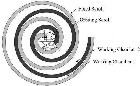
In summary, the final model of the asymmetric variable diameter base circle involute scroll is shown in Fig. 5.
Fig. 5Asymmetric variable diameter base circle involute scroll
3. Performance study under identical pressure ratio
3.1. Asymmetric circular involute scroll model
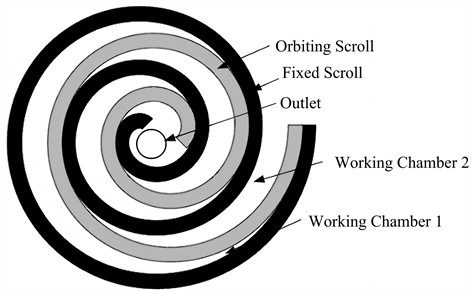
To quantitatively illustrate the performance of the asymmetric variable diameter base circle involute scroll profile, an asymmetric circular involute scroll profile is introduced for comparison. The fundamental parameters of this circular involute profile are identical to those of the asymmetric variable diameter base circle involute, and the volume ratios of its two working chambers are also maintained at the same value. The model of the asymmetric circular involute scroll is shown in the figure below.
Fig. 6Asymmetric circular involute scroll
3.2. Area utilization ratio
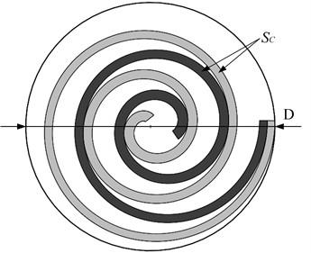
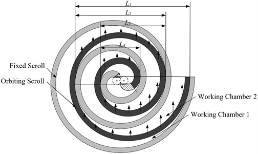
Under the same compression ratio condition, the asymmetric variable diameter base circle involute scroll exhibits a more compact structure. The area utilization ratio of the scroll wrap is used to evaluate material usage and quantitatively compare the structural size of scroll compressors. A smaller area utilization ratio indicates better economic efficiency [18-20]. The area utilization ratio is defined as the ratio of the axial projection area of the fixed and orbiting scrolls to the area of the minimum enclosing disk diameter during their engagement, as illustrated in the figure.
The engagement dimension of the asymmetric circular involute scroll is:
The engagement dimension of the asymmetric variable diameter base circle involute scroll is:
Thus, the expression for the area utilization ratio of the scroll is:
where represents the terminal unfolding angle of the scroll profile; denotes the axial projection area of the fixed and orbiting scrolls.
The geometric parameters and area utilization ratios of the two models under identical working conditions are listed in Table 2.
Table 2Comparison of geometric parameters and area utilization ratios between the two models
Profile type | Compression ratio | Engagement disk diameter / mm | Area utilization ratio |
Circular involute | 3 | 103.13 | 0.375 |
Variable base circle involute | 3 | 95.31 | 0.347 |
As indicated in the table, under equal compression ratio conditions, the asymmetric variable diameter base circle involute profile achieves a 7.58 % reduction in the engagement disk diameter compared to the circular involute profile, resulting in a more compact structure. Furthermore, even with the reduced engagement disk diameter, the area utilization ratio of the variable diameter base circle involute profile decreases by 7.47 %. Consequently, the asymmetric variable diameter base circle involute scroll possesses a more compact structure and offers better material economy, making it suitable for applications with stringent spatial constraints.
Fig. 7Schematic diagram of area utilization calculation
3.3. Working chamber volume variation
The volume variation of the working chambers in the asymmetric variable diameter base circle involute scroll during operation is illustrated in Fig. 8.
Fig. 8Volume variation curves of the two structures
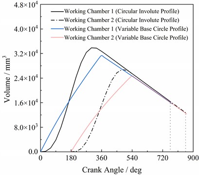
As shown in Fig. 8, the volume variation pattern of this model is similar to that of the circular involute model. Initially, the volume of working chamber 1 continuously increases until the main shaft rotation angle reaches 360°, marking the end of the suction process. The volume at this point represents the theoretical suction volume, after which the compression stage begins. Exhaust commences when the predetermined final compression volume is reached. Similarly, the compression process of working chamber 2 follows the same pattern, but its suction process starts half a revolution later. When the suction process of working chamber 2 concludes, the volumes of both working chambers become consistent.
Due to the more compact structure of the asymmetric variable diameter base circle involute scroll and the reduced engagement disk diameter, both the suction volume and the final compression volume of the asymmetric variable diameter base circle involute scroll experience a slight decrease – approximately 3.8 % – compared to those of the asymmetric circular involute scroll.
3.4. Gas force comparison
1)Axial Gas Force.
The gas forces generated during the operation of a scroll compressor directly affect its working efficiency. Among these, the axial gas force is the most significant force acting on the scroll wrap. It acts along the direction of the main shaft axis. Excessive gas force can cause the orbiting scroll to separate from the fixed scroll, thereby increasing the axial clearance and raising the radial leakage. Based on the characteristics of the asymmetric scroll structure, the calculation formula for the axial gas force is:
where, , , represent the pressures in the three distinct stages of compression occurring in working chamber 1. Specifically, denotes the pressure immediately after suction ends, represents the discharge pressure, and signifies the pressure during the intermediate stage. , , denote the corresponding areas of working chamber 1 at these respective states. Similarly, , represent the pressures in working chamber 2, and , denote the corresponding areas of working chamber 2 at these states.
2) Tangential Gas Force.
The gas force acting on the orbiting scroll along the tangential direction of the main shaft is referred to as the tangential gas force:
where , , and represent the tangential projection lengths of the scroll wrap surfaces subject to pressure differences. Their calculation method is as follows:
– When :
– When :
where , (1, 2, 3) are the unfolding angles of the outer profiles of the fixed and orbiting scrolls at the meshing point.
This force results from the pressure differences between adjacent working chambers, and its mechanical principle is illustrated in Fig. 9.
Fig. 9Diagram of tangential gas force
Owing to its more compact structure, the asymmetric variable diameter base circle involutes scroll generates lower gas forces under identical operating conditions.
Transient CFD simulations with identical numerical setups were conducted for both scrolls to acquire gas force data. Simulations adopted atmospheric-temperature pressure inlet and pressure outlet matching compression ratio 3.0 with adiabatic no-slip walls, where the orbiting scroll rotated periodically; the SST - turbulence model was selected for accurate prediction of narrow clearance flow and pressure fluctuation, and tetrahedral meshes with local refinement on clearances and exhaust ports were used. Grid independence test verified that the mesh of 2.1 million cells brought less than 1.1 % deviation of peak axial gas force, which was finally adopted for calculation. The transient gas force results under unified settings are displayed in the following figures.
As shown in Fig. 10, the axial gas force of the asymmetric scroll increases gradually during the suction and compression processes. Within one cycle, the tangential gas force of the asymmetric circular involute scroll reaches its maximum at main shaft rotation angles of 66°, 152°, 241°, and 330°, respectively. The theoretical exhaust angles for the two working chambers are 45° and 135°. When the exhaust stage is reached, the small flow area of the exhaust port causes the pressure in the working chamber to continue rising, consequently leading to a further increase in the tangential gas force. Similarly, for the asymmetric variable diameter base circle involute scroll, the tangential gas force peaks at 49°, 138°, 227°, and 318° within one cycle. The initial theoretical exhaust angles for its two working chambers are 55.908° and 141.312°, where the pressure and tangential gas force also continue to increase. From Fig. 11, it can be observed that the variation trends of the axial gas forces for both structures are similar. Both exhibit a significant increase during the exhaust process. This is because the working chamber pressure reaches its maximum at the onset of exhaust, and over-compression further elevates the pressure, resulting in the axial gas force peaking within the cycle. Furthermore, Fig. 10 and Fig. 11 indicate that, under identical conditions, the asymmetric variable diameter base circle involute scroll exhibits lower axial and tangential gas forces compared to the asymmetric circular involute scroll. The peak values of these two gas forces are reduced by 2.5 % and 8.2 %, respectively, while the average tangential force over one cycle is reduced by 12.6 %. This improvement is attributed to its more compact structural dimensions.
Fig. 10Axial gas forces
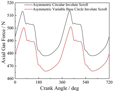
Fig. 11Tangential gas forces
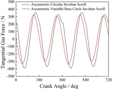
Fig. 12 shows the radial gas forces for both structures. The magnitude of the radial gas force is primarily related to the pressure differences across different working chambers and the size of the base circle radius. The peaks of the radial and tangential gas forces for the two structures exhibit opposite trends. The radial gas force fluctuates significantly because it pushes the orbiting scroll towards the fixed scroll, and the pressure in the radial clearance between them varies considerably during the compression process, leading to strong pulsations in the radial gas force. Compared to the circular involute scroll, the peak radial gas force of the variable diameter base circle involute scroll is reduced by 21.3 %, and its average value over one cycle is reduced by 17.4 %. This is associated with the shorter leakage path length and reduced internal leakage in the asymmetric variable diameter base circle involute scroll.
Fig. 12Overturning moments of the two structures
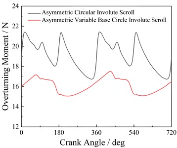
Fig. 13Self-rotation moments of the two structures
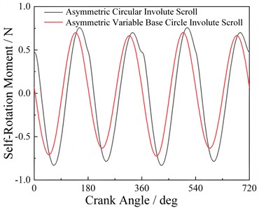
Fig. 13 shows the variation of the overturning moment with the rotation angle. The overturning moment is determined by the radial force, tangential force, and the scroll wrap height. An excessively large overturning moment can destabilize the orbiting scroll’s operation and increase friction between the end faces of the fixed and orbiting scrolls. As shown in the figure, the overturning moments of both structures fluctuate periodically with the exhaust process, gradually increasing during exhaust and then decreasing until the next exhaust begins. Within one cycle, the peak and average overturning moments of the asymmetric variable diameter base circle involute scroll are lower than those of the asymmetric circular involute scroll.
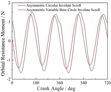
Fig. 14 displays the variation curves of the self-rotation moment and the orbital resistance moment for both structures. According to their calculation formulas, both moments are generated by components of the tangential force. The former tends to induce self-rotation of the orbiting scroll during operation, while the latter hinders its orbital motion, both adversely affecting the scroll's operation. Numerically, the orbital resistance moment is twice the self-rotation moment. The pulsation and variation patterns of both moments are consistent with those of the tangential force, increasing with rising chamber pressure. Compared to the circular involute scroll, the peak self-rotation and orbital resistance moments of the asymmetric variable diameter base circle involute scroll over one cycle are reduced by 7.6 %. Therefore, the operation of the asymmetric variable diameter base circle involute scroll is more stable.
From the above analysis, it can be concluded that under the same pressure ratio conditions, the asymmetric variable diameter base circle involute scroll not only has a more compact structure but also exhibits superior mechanical performance compared to the asymmetric circular involute scroll.
Fig. 14Orbital resistance moments of the two structures
3.5. Performance investigation under identical structural dimensions
As shown Fig. 15, a scroll compressor test platform was designed and constructed for subsequent performance testing. The core experimental objectives are to test the suction flow, internal pressure change and gas force of the scroll compressor under various operating conditions, so as to quantitatively evaluate the comprehensive performance of the novel asymmetric variable diameter base circle involute scroll. The test bench is composed of a scroll compressor prototype, flowmeters, pressure sensors, a rotating speed tachometer and an automatic control system.
For the asymmetric circular involute scroll compressor, the engagement condition between its fixed and orbiting scrolls is given by:
To ensure the two scroll models share the same overall outline size, we take the engagement disk diameter of the asymmetric circular involute scroll as the constraint condition. Combined with the geometric relationship of the variable diameter base circle involute profile and the scroll engagement dimension formula, we substitute the known structural parameters including initial base circle radius, base circle radius variation coefficient and crank eccentric distance for iterative calculation. The solved terminal unfolding angle of the asymmetric variable diameter base circle involute is about 6.56. On the premise of keeping all other parameters consistent, we rebuild the asymmetric variable diameter base circle involute scroll model with equal overall dimensions. The geometric parameters of the two models are compared and summarized in Table 3.
Fig. 15Scroll compressor test platform
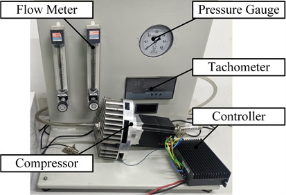
Table 3Comparison of geometric parameters between the two models under identical dimensions
Profile type | Engagement disk diameter (mm) | Suction volume (mm3) | Compression ratio |
Circular involute | 103.13 | 58160 | 3.00 |
Variable base circle involute | 103.13 | 64480 | 3.49 |
Taking the start of suction in working chamber 1 as , the volume variation curve of the asymmetric variable diameter base circle involute scroll with identical engagement dimensions to the circular involute structure is shown in Fig. 16.
Fig. 16Volume variation of the asymmetric variable diameter base circle involute scroll with identical meshing dimensions
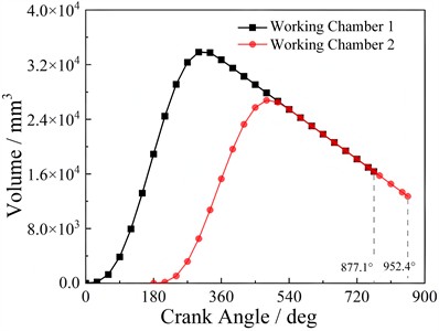
As shown in Fig. 16, the volume variation trend of this structure is basically consistent with the previous configuration. The two working chambers exhibit a 180° phase difference in their suction angles. Working chamber 1 completes its suction process at a main shaft rotation angle of 360°, while working chamber 2 completes suction at 540°. When suction ends, the volumes of the two chambers reach 34,972.88 mm3 and 28,411.32 mm3, respectively. Subsequently, they enter the compression process, with exhaust beginning at rotation angles of 877.1° and 952.4°, respectively.
The data indicates that, under identical engagement dimensions, the suction volumes of the two working chambers in the asymmetric variable diameter base circle involute scroll increase by 6.90 % and 11.66 %, respectively, compared to the asymmetric circular involute scroll. Consequently, the total suction volume increases by 8.98 %.
Due to the increased suction volume, the inlet and outlet mass flow rates of the asymmetric variable diameter base circle involute scroll also rise. The variation curves of the mass flow rates with rotation angle for both structures are shown in Fig. 17 and Fig. 18.
Fig. 17Inlet mass flow rate versus rotation angle
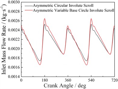
Fig. 18Outlet mass flow rate versus rotation angle
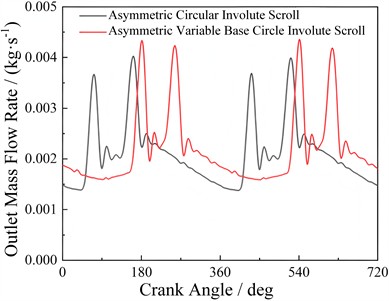
As shown in Fig. 17 and Fig. 18, the inlet and outlet mass flow rates of both structures exhibit periodic fluctuations synchronized with the suction and exhaust processes. While the fluctuation patterns during the suction phase are fundamentally similar between the two configurations, the peak inlet mass flow rate per cycle of the asymmetric variable diameter base circle involute scroll is approximately 4.81 % higher than that of the asymmetric circular involute scroll. The outlet mass flow rates of both structures increase during the exhaust phases of their respective working chambers. However, due to differences in both the initiation timing of exhaust and the magnitude of discharged volume between the two structures, their outlet mass flow rate fluctuation patterns differ. Specifically, the peak exhaust mass flow rate of the asymmetric variable diameter base circle involutes scroll within one cycle increases by 8.35 %, which is attributable to its larger suction volume.
4. Conclusions
This study summarizes and elaborates on two initiation methods for the variable-diameter base circle scroll profile; based on the normal equidistant method, it derives the calculation formula for the axial projection area of the crescent-shaped working chamber under the condition that both the inner and outer variable-diameter base circle involute profiles have generating angles simultaneously, and further establishes an asymmetric variable-diameter base circle involute scroll model with equal volume ratio by shortening the tooth heads of the asymmetric scroll. Performance comparisons between this proposed scroll model and the asymmetric circular involute scroll are conducted under two sets of comparative conditions: under the same geometric parameters and compression ratio, the asymmetric variable-diameter base circle involute scroll reduces the structural size by 7.58 % and the area utilization ratio by 7.47 %, reflecting advantages in material saving and economic efficiency, while the derived and compared gas force calculation principles show that the peak axial, tangential, and radial gas forces of this structure within one cycle are reduced by 2.5 %, 8.2 %, and 21.3 % respectively, with the maximum values of overturning moment, self-rotation moment, and orbital resistance moment also decreasing, which verifies its superior mechanical performance; under the same structural dimensions, the proposed scroll model achieves an 8.98 % increase in total suction volume per cycle and an 8.35 % increase in peak exhaust mass flow rate, indicating better operational performance. In conclusion, the asymmetric variable-diameter base circle involute scroll demonstrates excellent comprehensive performance, which can provide theoretical support and reference for the design and optimization of scroll compressors in specific application scenarios.
References
-
P. C. Shu, Z. W. Xing, and F. Cao, Rotary Compressor. (in Chinese), Xi'an, China: Xi'an Jiaotong University Press, 2020.
-
X. H. Chen et al., “Numerical simulation of an asymmetric asynchronous exhaust scroll compressor,” (in Chinese), Journal of Mechanical and Electrical Engineering, Vol. 40, No. 9, pp. 1433–1440, Apr. 2023.
-
K. Suefuji et al., “Scroll-type fluid machine with different terminal end wrap angles,” U.S. Patent No. 4.904.170, Feb. 1990.
-
Z. Qiao et al., “Tentative study of asymmetry wraps scroll compressor,” in International Compressor Engineering Conference at Purdue University, pp. 1–8, 1994.
-
B. R. Shaffer and E. A. Groll, “Variable wall thickness scroll geometry modeling with use of a control volume approach,” International Journal of Refrigeration, Vol. 36, No. 7, pp. 1809–1820, Aug. 2013, https://doi.org/10.1016/j.ijrefrig.2013.08.003
-
C. Y. Cao, “Generations of novel asymmetric wraps and investigation of working characteristics for scroll compressors,” (in Chinese), China University of Petroleum (East China), 2019.
-
X. W. Wang, “Numerical simulation of transient flow and investigation on the modifications of the suction flow passage in a scroll compressor,” (in Chinese), Xi’an University of Technology, Vol. 170, p. 115031, 2020, https://doi.org/10.1016/j.applthermaleng.2020.115031
-
J. Lian, L. Du, J. Luo, J. Xu, H. Xie, and Y. Li, “Design and numerical simulation of an new asymmetric variable-clearance scroll hydrogen circulation pump profile,” Flow Measurement and Instrumentation, Vol. 109, p. 103261, Feb. 2026, https://doi.org/10.1016/j.flowmeasinst.2026.103261
-
K. Tojo and H. Ueda, “Scroll type fluid compressor with an involute spiral based on a circle having a varying radius,” U.S. Patent No. 5.425.626, Jun. 1995.
-
Y. Liu, C. Hung, and Y. Chang, “Study on involute of circle with variable radii in a scroll compressor,” Mechanism and Machine Theory, Vol. 45, No. 11, pp. 1520–1536, Aug. 2010, https://doi.org/10.1016/j.mechmachtheory.2010.07.001
-
J. Wang et al., “Investigation of tapered meshing clearance and thickness scroll wrap,” (in Chinese), Journal of Engineering Thermophysics, Vol. 34, No. 8, pp. 1453–1456, Aug. 2013.
-
J. D. Wang, Z. Z. Zhang, and J. Y. Wei, “Research of the scroll expander with variable base circle radius involute,” (in Chinese), Fluid Machinery, Vol. 42, No. 6, pp. 33–36, Aug. 2014, https://doi.org/10.3969/j.issn.1005-0329.2014.06.007
-
J. N. Ding et al., “Study on the circular profile of scroll compressors with changing radii,” (in Chinese), Journal of Northeastern University (Natural Science), Vol. 40, No. 5, pp. 722–727, May 2019, https://doi.org/10.12068/j.issn.1005-3026.2019.05.022
-
L. Huang, C. Qiu, Y. Wang, M. Wu, S. Ren, and C. Miao, “Analysis of tangential leakage flow characteristics in a variable diameter dual circular arc vortex compressor,” Applied Sciences, Vol. 14, No. 6, p. 2262, Mar. 2024, https://doi.org/10.3390/app14062262
-
K. Li, R. Li, L. Xiao, and N. Gao, “Effect of various conditions on the formation number of vortex rings: a review,” Physics of Fluids, Vol. 37, No. 5, p. 051305, May 2025, https://doi.org/10.1063/5.0268670
-
X. Kang, S. Ma, X. Wang, A. Zhang, J. Hu, and G. Xia, “Nonlinear dynamics of low frequency compact piezoelectric energy harvesting vibration system by a cucurbit flute-inspired beam with intelligent adjustable,” Chaos, Solitons and Fractals, Vol. 208, p. 118315, 2026, https://doi.org/10.1016/j.chaos.2026.118315
-
X. Wang, X. Kang, L. Ji, A. Zhang, and G. Xia, “Low frequency vibration energy harvesting of bio-inspired multi-stable piezoelectric vibration system with an adjustable device,” Chaos, Solitons and Fractals, Vol. 192, p. 116026, 2025, https://doi.org/10.1016/j.chaos.2025.116026
-
X. Kang, X. Wang, and G. Xia, “Ultra-low frequency vibration energy harvesting of piezoelectric vibration systems with an adjustable device,” Alexandria Engineering Journal, Vol. 100, pp. 92–110, May 2024, https://doi.org/10.1016/j.aej.2024.05.035
-
Z. Pengcheng, P. Bin, and Z. Yubo, “Comprehensive analysis of geometric performance of circular involute variable thickness scroll compressor,” (in Chinese), Journal of Mechanical Engineering, Vol. 56, No. 23, p. 118, Jan. 2021, https://doi.org/10.3901/jme.2020.23.118
-
C. S. Hou and T. Liu, “Construction and performance investigation of variable cross-section scroll profiles based on Frenet frame,” (in Chinese), Journal of Shanghai Jiao Tong University, Vol. 53, No. 12, pp. 1495–1501, Dec. 2019, https://doi.org/10.16183/j.cnki.jsjtu.2019.12.013
About this article

This research was supported by National Development and Investment Group Co., Ltd. Science and Technology Project (SDIC2023-03), Provincial Natural Science Distinguished Young People Project of Anhui Universities and Colleges (2022AH020025), Cultivation Project of Discipline (Specialty) Leaders of Anhui Province (DTR2024022), Open Foundation of Anhui Province Key Laboratory of Critical Friction Pair for Advanced Equipment [No. LCFP-2505].
The datasets generated during and/or analyzed during the current study are available from the corresponding author on reasonable request.
Hao Li: Investigation, methodology, writing-original draft. Zhiyuan Zhang: Investigation, data curation, writing-original draft. Weikang Liu: Data curation, writing-review and editing. Xuehui Chen: Validation, writing-review and editing. Congmin Li: validation, resources, data curation. Wei Liu: Supervision, methodology, writing-review and editing.
The authors declare that they have no conflict of interest.

