Abstract
The paper analyses the design solutions of modern foreign passenger car bogies, on the basis of which a modernisation of the 68-921 (68-922) bogie frame manufactured by JSC “TVSRZ” is proposed. Long-term operating experience confirms its high strength and dynamic performance due to the significant load-bearing capacity of the frame elements. However, previous studies have revealed reserve strength in the main structural components, resulting in increased tare weight of the bogie and the vehicle as a whole. The proposed modernisation involves optimisation of the cantilever sections, cross beams, central suspension elements and cross stops, resulting in improved manufacturability and a reduction in frame weight by 106 kg (from 1760 to 1654 kg). The strength of the modernised design was evaluated using the finite element method in SolidWorks Simulation under three design modes. The results show that, despite weight reduction and structural modifications, the equivalent stresses (according to the von Mises criterion) comply with regulatory requirements for all considered loading conditions.
Highlights
- The modernised 68-921 bogie frame weight was reduced by 106 kg while maintaining required strength characteristics.
- Replacement of welded box-type cross beams with seamless round pipes improved manufacturability and reduced material consumption.
- Finite element analysis confirmed that maximum equivalent stresses remain below allowable limits in all design modes.
- The minimum safety factor of the modernised bogie frame is at least 1.7 under standard operational loading conditions.
- The proposed bogie frame design enables further development of high-speed passenger cars for operation up to 220 km/h.
1. Introduction
In recent years, passenger car manufacturing in the Republic of Uzbekistan has focused on developing a new generation of rolling stock that meets modern requirements for safety, comfort and economic efficiency [1-3]. Key priorities include reducing operating costs, improving energy efficiency and increasing the durability of load-bearing structures [4]. Achieving these goals requires optimisation of critical components, particularly bogies, which determine operational reliability, ride quality and dynamic interaction with the track [5]. Modern foreign passenger cars employ advanced bogies such as SF100, SF400, SF500, SF700, SF6500, SF7000, SF7500, SGP 400, SGP 950 and 25AN, developed by leading manufacturers including Siemens, Alstom, Talgo, Stadler Rail, CAF and H. Cegielski [6, 7]. These designs typically feature lightweight H-shaped welded frames, a lowered centre of gravity, air suspension and high-strength materials, ensuring improved stability, dynamic performance and passenger comfort [8, 9]. However, their direct application to 68-921 (68-922) bogies is limited by differences in body-bogie interfaces and layout features [10, 11]. Therefore, this study analyses selected foreign designs to identify applicable solutions and develop a weight-optimised modernisation of the 68-921 (68-922) bogie frame, characterised by structural simplification, reduced material consumption and preservation of strength and dynamic performance for implementation in bogies produced by JSC “TVSRZ”.
2. Analysis of the existing bogie design
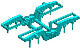
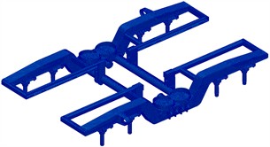
JSC “Tashkent Passenger Car Construction and Repair Plant” manufactures passenger and motor-car rolling stock, as well as bogies for 1520 mm gauge railways operating at speeds up to 160 km/h [12, 13]. The two-axle bogies are used in passenger, mail, baggage, dynamometric and high-capacity cars [14, 15] and are produced in two versions: 68-921 (7.1 t) and 68-922 (7.7 t). The main load-bearing element is frame 1 (Fig. 1(a)), formed by longitudinal and cross box-section beams 9 that transfer loads from the body to the track [11, 16]. The bogie also includes the over-spring beam 2, lead 3, wheel sets 4, axle boxes 5, hydraulic dampers 6, axle-box suspension 7, central suspension 8, and braking elements 10, 11 (Fig. 1(b)). Despite satisfactory strength and dynamic performance, reserve strength in key components enables weight reduction. Therefore, modernisation focuses on optimising structural elements and applying lightweight solutions while maintaining strength, improving manufacturability and enhancing high-speed performance.
Fig. 1General view of the 68-921 bolsterless bogie: 1 – bogie frame; 2 – crossbeam; 3 – lead; 4 – wheel sets; 5 – axle boxes; 6 – hydraulic vibration damper; 7 – axle suspension springs; 8 – central suspension springs; 9 – frame cross beams; 10 – brake brackets; 11 – crossbar with brake elements
a) Side view
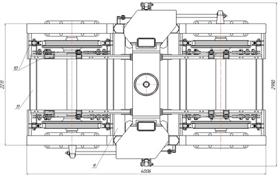
b) Top view
3. Modernisation of the bogie frame design
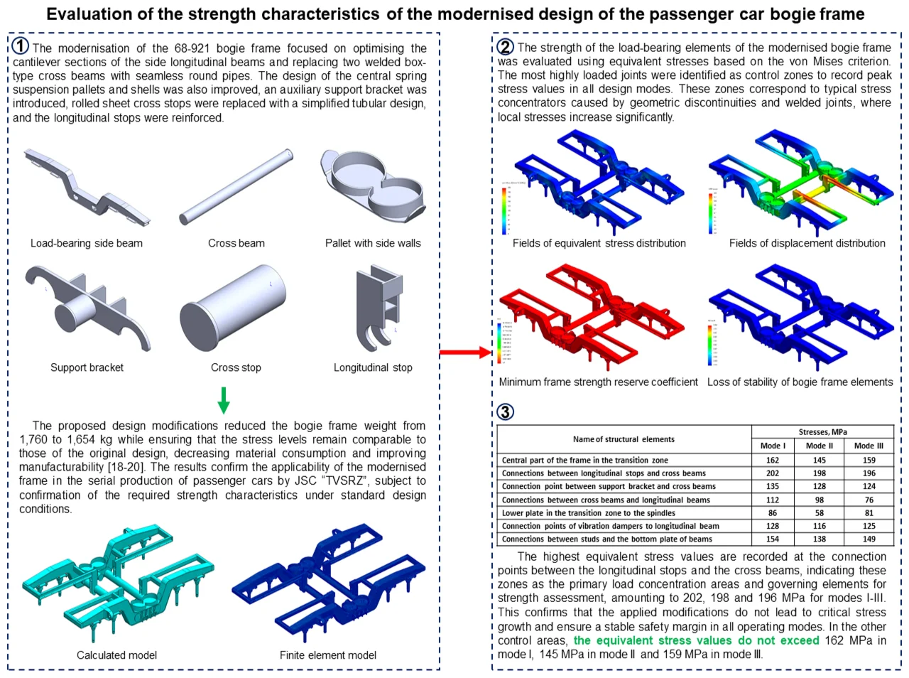
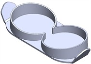
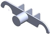
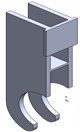
The modernisation of the 68-921 bogie frame focused on optimising the cantilever sections of the side longitudinal beams (Fig. 2(a)) and replacing two welded box-type cross beams with seamless round pipes (Fig. 2(b)) [10, 17]. The design of the central spring suspension pallets and shells was also improved (Fig. 2(c)), an auxiliary support bracket was introduced (Fig. 2(d)), rolled sheet cross stops were replaced with a simplified tubular design (Fig. 2(e)), and the longitudinal stops were reinforced (Fig. 2(f)).
Fig. 2Structural elements of the modernised bogie frame design
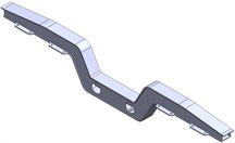
a) Load-bearing side beam

b) Cross beam
c) Pallet with side walls
d) Support bracket with cross stop
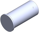
e) Cross stop
f) Longitudinal stop
4. Assessment of the strength of the modernised bogie frame design
The proposed design modifications reduced the bogie frame weight from 1,760 to 1,654 kg while ensuring that the stress levels remain comparable to those of the original design, decreasing material consumption and improving manufacturability [18-20]. The results confirm the applicability of the modernised frame in the serial production of passenger cars by JSC “TVSRZ”, subject to confirmation of the required strength characteristics under standard design conditions.
Fig. 3Calculation and finite element models of the modernised bogie frame showing geometry, mesh discretisation and boundary condition application
a) Calculated model
b) Finite element model
The strength of the load-bearing elements of the modernised frame was evaluated using the finite element method in SolidWorks Simulation [21]. The structure was modelled with three-dimensional solid elements, with mesh parameters selected based on convergence considerations and boundary conditions and loading schemes defined in accordance with requirements [20]. The finite element model comprised 1,573,284 elements and 2,737,010 nodes (Fig. 3(b)), which ensured the stability and convergence of the calculation results. The applied loads for the three standard design modes in accordance with [18] are presented in Table 1.
Table 1Values obtained using calculation formulas for three design modes
Value | Mode I | Mode II | Mode III |
Vertical dynamics coefficient, | – | 0.21 | 0.30 |
Calculated vertical load per bogie, max, kN | 300 | ||
Estimated additional vertical load, kN | 130 | 100 | 80 |
Calculated longitudinal load in one direction (maximum), kN | 70 | 45 | 45 |
Longitudinal load for diaphragm and vibration damper, kN | 12 | 10 | 10 |
Calculated lateral load in one direction (maximum), kN | – | – | 40.0 |
Inertia force of wheel sets, , kN | 62.5 | 37.5 | 25 |
Fig. 4 presents the kinematic and force boundary conditions and loading scheme used in the strength analysis of the bogie frame for design modes I-III. In mode III, an additional transverse load [22] was applied to one side of the cross stop in accordance with Table 1 values.
Fig. 4Calculation model, applied boundary conditions and control zones used for evaluation of equivalent stresses in the bogie frame: 1 – central frame transition zone; 2 – longitudinal stop-cross beam joint; 3 – support bracket-cross beam joint; 4 – cross-longitudinal beam joint; 5 – drawbar bracket-longitudinal beam joint; 6 – lower plate transition to spindles; 7 – vibration damper bracket-longitudinal beam joint; 8 – spindle-lower longitudinal beam joint
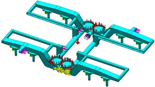
a) Kinematic and force boundary conditions
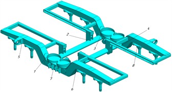
b) Control zones for measuring equivalent stresses
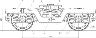
The strength of the load-bearing elements of the modernised bogie frame was evaluated in accordance with [18] using equivalent stresses based on the von Mises criterion. The most highly loaded joints were identified as control zones to record peak stress values in all design modes. These zones correspond to typical stress concentrators caused by geometric discontinuities and welded joints, where local stresses increase significantly. Monitoring these areas is therefore essential for assessing the strength and reliability of the modernised passenger car bogie frame.
5. Analysis of the results of theoretical studies
Based on the results of calculations, the equivalent stress fields for the modernised frame, comparable with the baseline design, were determined. Fig. 5 shows the results of the calculation for design mode I.
Fig. 5Equivalent stress, displacement and stability distribution results for design mode I of the bogie frame
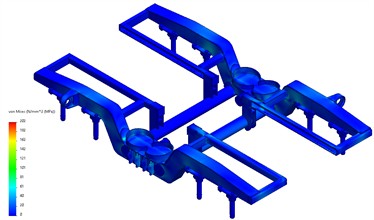
a) Fields of equivalent stress distribution
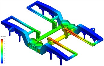
b) Fields of displacement distribution
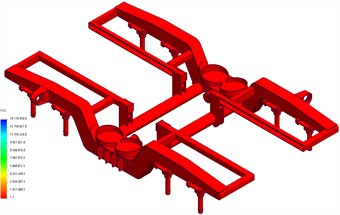
c) Minimum frame strength reserve coefficient
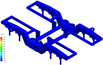
d) Loss of stability of bogie frame elements
For a comparative analysis of the results for the three calculation modes, the obtained values are summarised in Table 2.
Table 2Results of strength calculations for the bogie frame structure
Characteristic name | Mode I | Mode II | Mode III |
Permissible stresses, MPa | |||
310 | 220 | ||
Steel grade GOST 19281-89 | 345-09G2S | ||
Maximum equivalent stresses, MPa | 202 | 198 | 196 |
Maximum displacement of frame elements, mm | 0.8 | 0.8 | 0.7 |
Safety factor of frame structure, | 1.7 | 1.7 | 1.7 |
Frame element stability loss margin, | 1.6 | 1.7 | 1.7 |
The results of recording the maximum equivalent stresses, reflecting the distribution of loads between key structural joints, are presented in Table 3.
The highest equivalent stress values are recorded at the connection points between the longitudinal stops and the cross beams, indicating these zones as the primary load concentration areas and governing elements for strength assessment, amounting to 202, 198 and 196 MPa for modes I-III. This confirms that the applied modifications do not lead to critical stress growth and ensure a stable safety margin in all operating modes. In the other control areas, the equivalent stress values do not exceed 162 MPa in mode I, 145 MPa in mode II and 159 MPa in mode III.
Table 3Maximum equivalent stresses in the control areas of the bogie frame structure
Name of structural elements | Stresses, MPa | ||
Mode I | Mode II | Mode III | |
Central part of the frame in the transition zone | 162 | 145 | 159 |
Connections between longitudinal stops and cross beams | 202 | 198 | 196 |
Connection point between support bracket and cross beams | 135 | 128 | 124 |
Connections between cross beams and longitudinal beams | 112 | 98 | 76 |
Lower plate in the transition zone to the spindles | 86 | 58 | 81 |
Connection points of vibration dampers to longitudinal beam | 128 | 116 | 125 |
Connections between studs and the bottom plate of beams | 154 | 138 | 149 |
6. Conclusions
The modernisation of the bogie frame of models 68-921 (68-922) reduced its weight by 106 kg while maintaining strength. The maximum equivalent stresses (according to Mises’ theory) were: in mode I – 202 MPa (allowable 310 MPa), in mode II – 198 MPa (allowable 310 MPa), and in mode III – 196 MPa (allowable 220 MPa). The analysis shows that the load-bearing elements of the 68-921 bogie frame withstand the specified static and dynamic loads without critical stress concentrations, with a minimum safety factor of at least 1.7, meeting regulatory requirements [18]. The results confirm that weight reduction is achieved without loss of strength, while maintaining sufficient safety margins under operational conditions. Further research should focus on comprehensive computational and experimental assessment of dynamic behaviour and service life to develop reliable high-speed passenger car bogies for operation on the railways of the Republic of Uzbekistan at speeds of up to 220 km/h.
References
-
C. Mızrak and I. Esen, “The optimisation of rail vehicle bogie parameters with the fuzzy logic method in order to improve passenger comfort during passage over bridges,” International Journal of Heavy Vehicle Systems, Vol. 24, No. 2, pp. 113–139, Feb. 2017, https://doi.org/10.1504/ijhvs.2017.10003612
-
R. K. Luo, B. L. Gabbitas, and B. V. Brickle, “Fatigue life evaluation of a railway vehicle bogie using an integrated dynamic simulation,” Proceedings of the Institution of Mechanical Engineers, Part F: Journal of Rail and Rapid Transit, Vol. 208, No. 2, pp. 123–132, Dec. 1994, https://doi.org/10.1243/pime_proc_1994_208_242_02
-
M. Yamamoto, “Non-parametric optimization of railway wheel web shape based on fatigue design criteria,” International Journal of Fatigue, Vol. 134, p. 105463, Dec. 2020, https://doi.org/10.1016/j.ijfatigue.2019.105463
-
L. Ding, Z. He, and B. Chen, “Strength assessment and lightweight optimization design of a bogie frame based on the structural stress method,” International Journal of Structural Integrity, Vol. 16, No. 1, pp. 159–186, Apr. 2025, https://doi.org/10.1108/ijsi-04-2024-0056
-
R. Xiu, M. Spiryagin, Q. Wu, S. Yang, and Y. Liu, “Fatigue life assessment methods for railway vehicle bogie frames,” Engineering Failure Analysis, Vol. 116, p. 104725, Oct. 2020, https://doi.org/10.1016/j.engfailanal.2020.104725
-
Y. Yaohui, “Study on fatigue reliability of welded frame of railway passenger car bogie,” Southwest Jiaotong Univercity, Chengdu, China, 2011.
-
B. R. Miao, Y. X. Luo, Q. M. Peng, Y. Z. Qiu, H. Chen, and Z. K. Yang, “Multidisciplinary design optimization of lightweight carbody for fatigue assessment,” Materials and Design, Vol. 194, p. 108910, Nov. 2020, https://doi.org/10.1016/j.matdes.2020.108910
-
H. Zou, Q. Wu, and X. Zou, “Retraction note: research on optimization design of suspension parameters of railway vehicle bogies based on surrogate model,” Multimedia Tools and Applications, Vol. 85, No. 5, pp. 35091–35109, May 2026, https://doi.org/10.1007/s11042-026-21618-7
-
J. Dizo, M. Blatnicky, J. Harusinec, and A. Falendysh, “Modification and analyses of structural properties of a goods wagon bogie frame,” Diagnostyka, Vol. 20, No. 1, pp. 41–48, Nov. 2018, https://doi.org/10.29354/diag/99853
-
J. G. Cho, J. S. Koo, and H. S. Jung, “A lightweight design approach for an EMU carbody using a material selection method and size optimization,” Journal of Mechanical Science and Technology, Vol. 30, No. 2, pp. 673–681, Feb. 2016, https://doi.org/10.1007/s12206-016-0123-8
-
T. Guo, B. Chen, Y. Wang, G. Cai, M. Hou, and Q. Dong, “Vibration characteristics and fatigue performance of bogie frame with inner axle box for high-speed trains,” Machines, Vol. 13, No. 11, p. 1056, Nov. 2025, https://doi.org/10.3390/machines13111056
-
Y. Rong, J. Xu, Y. Huang, and G. Zhang, “Review on finite element analysis of welding deformation and residual stress,” Science and Technology of Welding and Joining, Vol. 23, No. 3, pp. 198–208, Feb. 2018, https://doi.org/10.1080/13621718.2017.1361673
-
B. Peng et al., “Determination of wheel polygonal wear limit and fatigue life of railway bogie frames considering wheel/rail excitation,” Engineering Failure Analysis, Vol. 169, p. 109220, Mar. 2025, https://doi.org/10.1016/j.engfailanal.2024.109220
-
R. V. Rahimov, F. F. Khikmatov, D. S. Zafarov, and F. S. Galimova, “Conversion of a passenger wagon into a dynamometric wagon for railways of the Republic of Uzbekistan,” in AIP Conference Proceedings, Vol. 3282, No. 1, p. 070002, 2025, https://doi.org/10.1063/5.0266047
-
R. Rahimov, Y. Boronenko, F. Galimova, and D. Zafarov, “Passenger carriage with increased capacity for railways of the Republic of Uzbekistan,” in Communications in Computer and Information Science, Vol. 2767, Cham: Springer Nature Switzerland, 2026, pp. 157–169, https://doi.org/10.1007/978-3-032-13672-5_14
-
V. Nieminen, A. Tuohineva, and M. Autio, “Wheel load reconstruction using strain gauge measurements on the bogie frame for strain prediction and fatigue assessment,” International Journal of Fatigue, Vol. 170, p. 107533, 2023, https://doi.org/10.1016/j.ijfatigue.2023.107533
-
D. Chen et al., “Study on damage, equivalent stress and life distribution characteristics of bogie frame of high-speed train,” Journal of Mechanical Engineering, Vol. 56, No. 22, pp. 237–246, 2020, https://doi.org/10.3901/jme.2020.22.237
-
“Standards for the calculation and design of new and modernised railway carriages with a gauge of 1520 mm (non-self-propelled),” VNIIV-VNIIZHT, Moscow, Russia, 1983.
-
“Bogies for locomotive-hauled passenger carriages. Technical conditions,” Standardinform, Moscow, Russia, GOST R 55821-2013, 2016.
-
“Rail transport. Rules for the design and testing of bogie frame structures,” Standardinform, Moscow, Russia, GOST R 53077-2008, 2009.
-
D. Deng, H. Murakawa, and W. Liang, “Numerical simulation of welding distortion in large structures,” Computer Methods in Applied Mechanics and Engineering, Vol. 196, No. 45-48, pp. 4613–4627, 2007, https://doi.org/10.1016/j.cma.2007.05.023
-
R. Rahimov, Y. Boronenko, A. Tretyakov, and S. Sultonov, “A new way to determine the indicators of vertical and horizontal of a subway car,” E3S Web of Conferences, Vol. 383, p. 01017, 2023, https://doi.org/10.1051/e3sconf/202338301017
About this article

The authors have not disclosed any funding.
The datasets generated during and/or analyzed during the current study are available from the corresponding author on reasonable request.
The authors declare that they have no conflict of interest.
