Active vibration isolation control method for cold atom gravimeter based on output delay observer

Dongyun Luo1
Xingyang Luo2
Shili Long3
Changshou Deng4
1, 2, 3, 4School of Electronic Information Engineering, Jiujiang University, Jiujiang, 332005, Jiangxi, China
1, 4Jiujiang Key Laboratory of Artificial Intelligence, Jiujiang University, Jiujiang, 332005, Jiangxi, China
Corresponding Author: Dongyun Luo
Download PDF

Abstract

Cold atom gravimeters are high-precision instruments for measuring gravitational acceleration; however, their accuracy is highly susceptible to ground-vibration disturbances, especially in dynamic environments. Effective suppression of vibration-induced noise is therefore essential for improving the performance of such systems. This study aims to develop an active vibration-isolation method that compensates for delayed output measurements and suppresses vibration-induced displacement, velocity, and atom-interference phase noise in cold atom gravimeters. A dynamic state-space model of the active vibration isolation platform was established by considering the passive isolation structure, voice-coil actuator, ground-vibration disturbance, and output delay. An output delay observer (ODO) was designed to estimate the platform displacement and velocity and was integrated with a proportional-derivative controller to generate the active feedback force. The stability of the complete observer-controller system was analyzed using a composite Lyapunov function. Simulations were conducted under sinusoidal excitations from 0.1 to 10 Hz, band-limited Gaussian white noise, and measured ground-vibration input. The proposed method was compared with proportional-integral-derivative and sliding mode control. The stability analysis showed that the closed-loop system is asymptotically stable under constant or slowly varying disturbances and uniformly ultimately bounded under bounded time-varying disturbances. The proposed method produced the smallest displacement and velocity responses under all investigated conditions. The residual vibration noise was 91.13 %-95.95 % lower than that obtained using proportional-integral-derivative control and 71.30 %-95.21 % lower than that obtained using sliding mode control. The phase-noise standard deviation was reduced to 7.05×10⁻⁴ rad, representing reductions of 95.10 % and 84.95 % relative to the two comparison methods, respectively. The output delay-observer-based active vibration isolation method provides an effective solution for suppressing vibration disturbances in cold atom gravimeters. The proposed control strategy significantly improves measurement accuracy and offers strong potential for high-precision gravimeter measurements in dynamic environments.

1. Introduction

Cold atom gravimeters have been widely applied in resource exploration, defense navigation, scientific research, and metrology [1-4]. State-of-the-art instruments have achieved sensitivities on the order of 2.2 μGal/√Hz and measurement precision at the level of 10-9) [5-6]. However, in practical operating environments, ground vibration noise remains a primary factor limiting further improvements in measurement performance. To mitigate vibration-induced degradation, a variety of suppression strategies have been developed, including passive and active isolation, as well as vibration compensation methods [7-9]. Among these approaches, active vibration isolation, which employs sensors and actuators within a closed-loop control framework, demonstrates superior attenuation performance in the low-frequency range compared to passive techniques. This capability makes it particularly well-suited for high-precision gravimeter measurements under dynamic conditions.

Hensley employed a suspended spring structure combined with air-bearing constraints to control the vertical motion of key components [10]. At the same time, accelerometers and actuators were incorporated to generate feedback forces that suppress vibration in the cold-atom gravimeter. Although effective, this approach was limited by structural complexity, large system volume, and stringent space requirements. Subsequently, Freier introduced a simplified configuration based on a Minus K passive isolation platform, with the accelerometer mounted directly on the platform surface. This design reduced system size and improved operational stability [11]. Building upon this framework, Tang Biao further optimized the system, reducing vibration noise by approximately two orders of magnitude [12]. Further advancements include a compact, low-frequency vertical active isolation system proposed by Gong Wenbin [13] and a tilt stabilization mechanism introduced by F. E. Oon, which enhanced vibration-suppression performance in static measurement scenarios [14]. To address ultra-low-frequency disturbances, Yao Jiamin proposed a two-stage active vibration isolation system inspired by the Superspring concept. By incorporating a geometric negative-stiffness mechanism, the system significantly reduced the uncertainty in gravity measurements under complex environmental conditions [15-16]. More recently, Zhou Minkang developed a three-dimensional vibration-isolation method to mitigate coupling between horizontal and vertical vibrations, achieving effective suppression in multiple directions [17-18]. Chen Bin further proposed a portable three-dimensional isolation system that enables both high performance and system mobility [19].

Despite significant progress in vibration suppression for cold atom gravimeters, the impact of output delay in active vibration-isolation systems remains insufficiently addressed. Such delays, arising from sensor signal processing, actuator dynamics, and computational latency, can degrade control performance and even compromise system stability, particularly in low-frequency, high-precision measurement scenarios. To overcome this limitation, the output delay effect in an active vibration isolation system subject to external disturbances, including ground vibrations, is systematically investigated. An active isolation strategy that integrates an output-delay observer with a proportional-derivative control scheme is proposed. Comparative simulation results demonstrate that the proposed method achieves superior suppression of both vibration displacement and velocity compared to conventional approaches. The proposed framework provides an effective, practically implementable solution to enhance the measurement accuracy of cold-atom gravimeters under dynamic conditions [20-21].

2. Active vibration isolation platform design and modeling

Active vibration isolation systems for atom gravimeters are commonly implemented on passive isolation platforms, augmented with vibration sensors and actuators to form a closed-loop control system [22-23]. In contrast to the limited low-frequency performance of purely passive isolation, active systems with comparable hardware configurations can exploit control strategies to reduce the system’s equivalent natural frequency effectively. This enables enhanced attenuation of low-frequency vibrations, thereby more effectively meeting the stringent requirements of high-precision gravimeter measurements [7, 24-26].

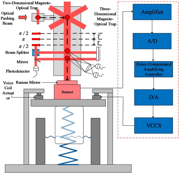
The structural schematic of the active vibration isolation platform is presented in Fig. 1. The system primarily comprises a base, an isolation platform, vibration sensors, actuators, and a control unit. The isolation platform serves as the mounting interface for critical optical components, such as the Raman retro-reflection mirror [27-28]. Vibration sensors acquire real-time motion signals from the platform. The measured signals are conditioned through amplification and analog-to-digital conversion before being processed by the delay-based controller. The computed control signals are subsequently converted back to analog form, power-amplified, and applied to voice coil motors, which generate control forces to suppress ground-induced vibrations actively.

The dynamic behavior of the active vibration isolation platform can be described by the following equation:

1
x¨=KVCYVCum-2ξ0ω0x˙-ω02x+2ξ0ω0y˙+ω02y,

where ξ0 denotes the damping coefficient of the system, ω0 is the natural frequency, x, x˙ and x¨ denote the displacement, velocity, and acceleration of the Raman mirror, respectively, y and y˙ represent the ground displacement and velocity, m is the mass of the Raman mirror, u is the control input, KVC is the gain coefficient of the voice coil motor, and YVC denotes the voltage-to-current conversion gain:

By introducing the substitution z=x   x˙, Eq. (1) can be rewritten as:

2
z˙t=Azt+Hut+W,

where A=01-2ξ0ω0-ω02, H=0KVCYVC/m, W=02ξ0ω0y˙+ω02y.

Fig. 1. Schematic diagram of the active vibration isolation platform structure
Schematic diagram of the active vibration isolation platform structure

3. Control algorithm design

To enhance the precision and stability of active vibration isolation in cold-atom gravimeters, an active control strategy that combines an output-delay observer (ODO) with proportional-derivative (PD) control is proposed [29-30]. The ODO estimates the platform’s vibration displacement and velocity states, compensating for sensor-induced time delays. To mitigate potential adverse effects of these delays on system stability, a dedicated stability function is designed to ensure the robustness of both the observer and the overall control system. The PD control strategy improves control accuracy, accelerates dynamic response, and reduces settling time while maintaining stable operation. By integrating the ODO with PD control, the proposed method effectively enhances low-frequency vibration suppression, thereby improving the cold atom gravimeter's measurement performance.

Due to the inherent delay in the output signal of the active vibration isolation system for cold atom gravimeters, the time delay in vibration displacement is denoted by Δ. Accordingly, the system output can be expressed as:

3
Vt=Czt-Δ,

where C=10.

The objective of the observer is to estimate the system vibration states. when t→∞, x^t=xt, x˙^t=x˙t, the variables x^t and x˙^t represent the observer’s estimates of the vibration displacement and velocity, respectively.

For the linear time-delay system, by introducing the substitution z^=x^x˙^T,the delay observer is designed as follows:

4
z^˙t=Az^t+Hut+KVt-Cz^t-Δ,

where z^t-Δ denotes the delayed system output signal z^t.Assume xd represents the desired vibration displacement of the system, and the derivative of the ideal position is x˙d, The control objective is defined as:

5
e=xd-z^t→e˙=x˙d-z^˙t,

where e denotes the tracking error between the desired displacement and the actual system output. The proportional-derivative control law is formulated as:

6
ut=kpe+kde˙,

where kp and kd are the proportional and derivative gain coefficients, respectively. To guarantee the stability of the output delay observer, the gain K must be appropriately selected such that all characteristic roots of Eq. (7) have negative real parts. This condition ensures the asymptotic stability of the observer. For the linear time-delay system, stability requires that the complex variable s lies in the open left-half complex plane:

7
sI-A+KCe-Δs=0.

4. Stability analysis of the closed-loop system with the PD controller and ODO

To address the stability of the complete observer-controller system, the closed-loop dynamics consisting of the vibration isolation platform, the PD controller, and the disturbance observer are analyzed in this subsection. The previous observer stability condition only guarantees the convergence of the observer error dynamics. Here, we further prove that the overall closed-loop system remains stable when the PD controller and the observer-based disturbance compensation are simultaneously included.

The active vibration isolation platform is described by:

8
x¨=bau-2ξ0ω0x˙-ω02x+Ft,

where F(t) denotes the lumped disturbance, including ground vibration and possible model uncertainty. Specifically:

9
Ft=2ξ0ω0y˙+ω02y+Δft,

where Δf(t) represents the lumped model uncertainty.

An extended state observer is introduced to estimate F(t). The observer error dynamics are given by:

10
Z~˙=A0-LC0Z~+HF˙,

where Z~ denotes the estimation error. By selecting the observer gain L such that A0-LC0 is Hurwitz, the observer error system is exponentially stable when F˙=0, and uniformly ultimately bounded for bounded disturbance variations.

The PD controller with disturbance compensation is designed as:

11
u=-kpx-kdx˙-F^ba.

Substituting this control law into the plant model yields:

12
x¨+cdx˙+cpx=F~,

where cd=bakd+2ξ0ω0, cp=bakp+ω02, and F~=F-F^ is the disturbance estimation error.

Considering the Lyapunov function:

13
Vx=12cpx2+12x˙2,

its derivative is:

14
V˙x=-cdx˙2+x˙F~.

Using Young’s inequality:

15
V˙x≤-cd-ε2x˙2+12εF~2.

Therefore, when cd>ε2, the plant subsystem is stable with respect to the observer estimation error. For the observer error subsystem, a Lyapunov function is selected as:

16
V0=Z~TP0Z~,

where P0>0 satisfies:

17
A0-LC0TP0+P0A0-LC0<0.

Thus:

18
V˙0<0,

for the ideal disturbance estimation condition.

A composite Lyapunov function is constructed as:

19
V=Vx+ηV0,

where η>0. The derivative satisfies:

20
V˙≤-λ1X2-λ2Z~2+λ3F˙2,

where λ1,λ2,λ3>0:

21
V˙≤-λ1X2-λ2Z~2+λ3F˙2.

Hence, for constant or slowly varying disturbances (F˙≈0):

22
V˙<0.

This proves that the complete ODO closed-loop system is asymptotically stable. For bounded time-varying disturbances, the closed-loop states and observer estimation errors remain uniformly ultimately bounded.

This analysis demonstrates that the stability of the proposed control system is guaranteed not only by the observer design but also by the interaction between the disturbance observer and the PD feedback controller.

5. Active vibration isolation control simulation

This section presents a comprehensive performance evaluation of the proposed control algorithm. The previously established active vibration-isolation model for the cold-atom gravimeter is used to analyze the system's response under specified disturbance conditions. The parameter values used in the MATLAB/Simulink simulations are listed in Table 1. These parameters include the mechanical parameters of the isolation platform, the actuator gain, the observer gain, the PD controller gains, and the output delay. Unless otherwise stated, all simulations in this section were carried out using the same parameter set, and only the external disturbance input was changed.

Numerical simulations were conducted to evaluate the vibration-suppression performance of the proposed ODO active vibration-isolation method. The active vibration isolation platform was modeled using the state-space representation derived in Section 2. The platform state was defined as z=xx˙T, where x and x˙ denote the displacement and velocity of the Raman retro-reflection mirror, respectively. The ground vibration was introduced into the system through the disturbance term related to the ground displacement y(t) and velocity y˙(t). The simulation parameters are listed in Table 1. These parameters include the mechanical parameters of the isolation platform, the actuator parameters, the observer gain, the controller gains, and the output delay. Unless otherwise stated, the same parameter set was used in all simulation cases, and only the external disturbance input was changed. The first two parameters in Table 1, ξ0 and ω0, define the damping ratio and natural frequency of the isolation platform. The parameters KVC, YVC, and m describe the voice-coil actuator and the equivalent mass of the Raman mirror. All numerical simulations were implemented in MATLAB. In the white-noise comparison, the continuous-time platform model was discretized using an exact zero-order-hold state transition obtained from the matrix exponential. The sampling interval was 0.001 s, the simulation duration was 100 s, and the first 20 s were excluded from the performance evaluation to eliminate transient effects. For the delay-sensitivity analysis involving sub-millisecond delays, a fixed-step forward-Euler method with a step size of 0.0001 s was used. The same initial conditions, disturbance inputs, simulation durations, and plant parameters were applied to all controllers. The observer gain K=139.14658.4T was used to correct the estimation error caused by the delayed output signal. The controller gains were set as Kp= 12000 and Kd= 10000, and the output delay was set as Δ= 0.001 s. These values were kept unchanged throughout the simulations to ensure a fair comparison among different disturbance conditions. Three types of disturbance inputs were considered. First, harmonic ground-vibration excitations at 0.1, 0.2, 0.5, 1.0, 2.0, 5.0 and 10 Hz were applied to evaluate the frequency-dependent isolation performance. Second, band-limited Gaussian white-noise excitation was used to assess the robustness of the controller under broadband random disturbance. Third, ground-vibration data were used as realistic environmental disturbance input.

Table 1. Simulation parameters of active vibration isolation
Symbol
Meaning
Parameter Value
ξ0
System damping ratio / N⋅s⋅m-1
0.1
ω0
System natural frequency / rad
4.396
kVC
Voice coil motor current gain coefficient / V⋅A-1
0.1
YVC
Voltage-to-force gain coefficient / N⋅A-1
7.6
m
Mass of the Raman mirror / kg
10
k
Matrix gain
[139.1; 4658.4]
KP
Gain coefficient
12000
Kd
Gain coefficient
10000
Δ
Delay time / s
0.001

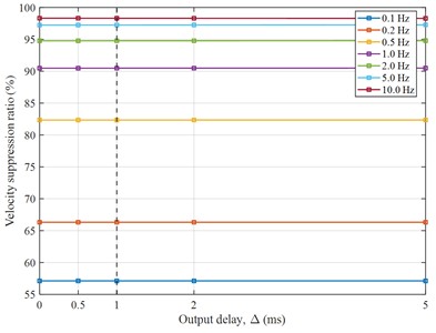
In the present numerical model, Δ= 1 ms was adopted as the nominal equivalent output-loop delay, representing the combined latency introduced by signal conditioning, analog-to-digital conversion, controller computation, digital-to-analog conversion, and actuator response. Because the controller has not yet been implemented on a physical platform, this value should be regarded as a representative simulation setting rather than a directly measured hardware delay. To evaluate the influence of this assumption, a numerical sensitivity analysis was conducted for Δ= 0, 0.5, 1, 2, and 5 ms, with all other plant, observer, and controller parameters kept unchanged.
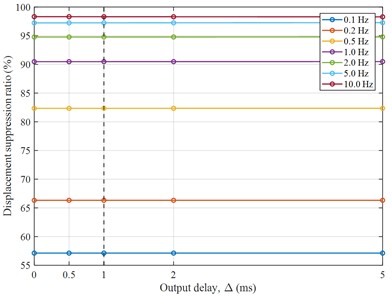
Fig. 2. Effect of the output delay on the suppression ratio of the ODO active vibration isolation system: a) effect of the output delay on the displacement suppression ratio of the ODO active vibration isolation system; b) effect of the output delay on the velocity suppression ratio of the ODO active vibration isolation system
Effect of the output delay on the suppression ratio of the ODO active vibration isolation system: a) effect of the output delay on the displacement suppression ratio of the ODO active  vibration isolation system; b) effect of the output delay on the velocity suppression ratio  of the ODO active vibration isolation system

a)

Effect of the output delay on the suppression ratio of the ODO active vibration isolation system: a) effect of the output delay on the displacement suppression ratio of the ODO active  vibration isolation system; b) effect of the output delay on the velocity suppression ratio  of the ODO active vibration isolation system

b)

As shown in Figs. 2, the displacement and velocity suppression ratios remain nearly unchanged throughout the investigated delay range. The attenuation performance is mainly dependent on the excitation frequency: the suppression ratios increase from approximately 57 % at 0.1 Hz to more than 98 % at 10 Hz. Only negligible variations are observed as the delay increases from 0 to 5 ms. Therefore, the nominal delay of 1 ms, indicated by the vertical dashed line, lies within a delay range in which the proposed ODO controller maintains bounded responses and consistent vibration-suppression performance.

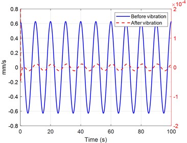
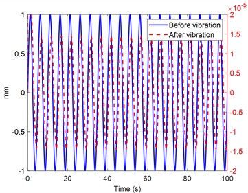
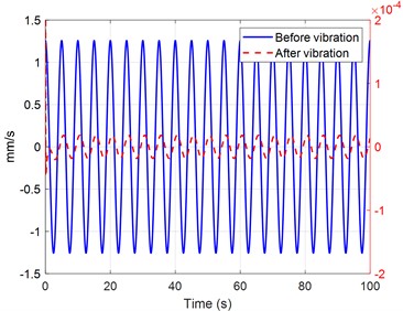
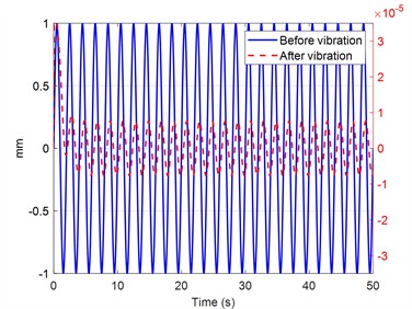
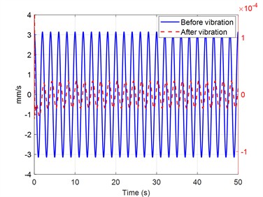
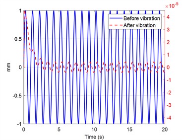
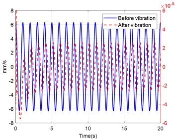
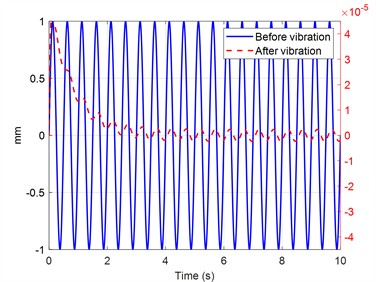
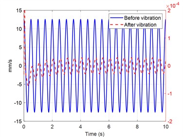
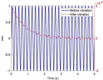
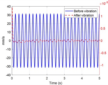
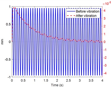
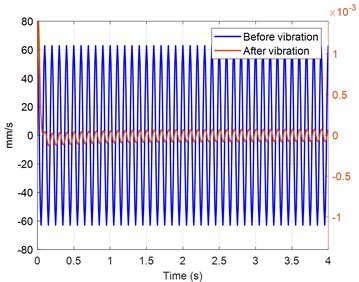
As illustrated in Fig. 3, the figure presents the displacement and velocity responses of the active vibration isolation system under sinusoidal base excitations at 0.1, 0.2, 0.5, 1, 2, 5, and 10 Hz.
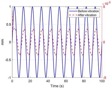
Fig. 3. Comparison of active vibration isolation performance at different excitation frequencies: a) comparison of displacement before and after active vibration isolation at 0.1 Hz; b) comparison of velocity before and after active vibration isolation at 0.1 Hz; c) comparison of displacement before and after active vibration isolation at 0.2 Hz; d) comparison of displacement before and after active vibration isolation at 0.2 Hz; e) comparison of displacement before and after active vibration isolation at 0.5 Hz; f) comparison of velocity before and after active vibration isolation at 0.5 Hz; g) comparison of displacement before and after active vibration isolation at 1 Hz; h)comparison of velocity before and after active vibration isolation at 1 Hz; i) comparison of displacement before and after active vibration isolation at 2 Hz; j) comparison of velocity before and after active vibration isolation at 2 Hz; k) comparison of displacement before and after active vibration isolation at 5 Hz; l) comparison of velocity before and after active vibration isolation at 5 Hz; m) comparison of displacement before and after active vibration isolation at 10 Hz; n) comparison of velocity before and after active vibration isolation at 10 Hz
Comparison of active vibration isolation performance at different excitation frequencies: a) comparison of displacement before and after active vibration isolation at 0.1 Hz; b) comparison of velocity before and after active vibration isolation at 0.1 Hz; c) comparison of displacement before and after active vibration isolation at 0.2 Hz; d) comparison of displacement before and after active vibration isolation at 0.2 Hz; e) comparison of displacement before and after active vibration isolation at 0.5 Hz; f) comparison of velocity before and after active vibration isolation at 0.5 Hz; g) comparison of displacement before and after active vibration isolation at 1 Hz; h)comparison of velocity before and after active vibration isolation at 1 Hz; i) comparison of displacement before and after active vibration isolation at 2 Hz; j) comparison of velocity before and after active vibration isolation at 2 Hz; k) comparison  of displacement before and after active vibration isolation at 5 Hz; l) comparison of velocity before and after active vibration isolation at 5 Hz; m) comparison of displacement before and after active vibration isolation at 10 Hz; n) comparison of velocity before and after active vibration isolation at 10 Hz

a)

Comparison of active vibration isolation performance at different excitation frequencies: a) comparison of displacement before and after active vibration isolation at 0.1 Hz; b) comparison of velocity before and after active vibration isolation at 0.1 Hz; c) comparison of displacement before and after active vibration isolation at 0.2 Hz; d) comparison of displacement before and after active vibration isolation at 0.2 Hz; e) comparison of displacement before and after active vibration isolation at 0.5 Hz; f) comparison of velocity before and after active vibration isolation at 0.5 Hz; g) comparison of displacement before and after active vibration isolation at 1 Hz; h)comparison of velocity before and after active vibration isolation at 1 Hz; i) comparison of displacement before and after active vibration isolation at 2 Hz; j) comparison of velocity before and after active vibration isolation at 2 Hz; k) comparison  of displacement before and after active vibration isolation at 5 Hz; l) comparison of velocity before and after active vibration isolation at 5 Hz; m) comparison of displacement before and after active vibration isolation at 10 Hz; n) comparison of velocity before and after active vibration isolation at 10 Hz

b)

Comparison of active vibration isolation performance at different excitation frequencies: a) comparison of displacement before and after active vibration isolation at 0.1 Hz; b) comparison of velocity before and after active vibration isolation at 0.1 Hz; c) comparison of displacement before and after active vibration isolation at 0.2 Hz; d) comparison of displacement before and after active vibration isolation at 0.2 Hz; e) comparison of displacement before and after active vibration isolation at 0.5 Hz; f) comparison of velocity before and after active vibration isolation at 0.5 Hz; g) comparison of displacement before and after active vibration isolation at 1 Hz; h)comparison of velocity before and after active vibration isolation at 1 Hz; i) comparison of displacement before and after active vibration isolation at 2 Hz; j) comparison of velocity before and after active vibration isolation at 2 Hz; k) comparison  of displacement before and after active vibration isolation at 5 Hz; l) comparison of velocity before and after active vibration isolation at 5 Hz; m) comparison of displacement before and after active vibration isolation at 10 Hz; n) comparison of velocity before and after active vibration isolation at 10 Hz

c)

Comparison of active vibration isolation performance at different excitation frequencies: a) comparison of displacement before and after active vibration isolation at 0.1 Hz; b) comparison of velocity before and after active vibration isolation at 0.1 Hz; c) comparison of displacement before and after active vibration isolation at 0.2 Hz; d) comparison of displacement before and after active vibration isolation at 0.2 Hz; e) comparison of displacement before and after active vibration isolation at 0.5 Hz; f) comparison of velocity before and after active vibration isolation at 0.5 Hz; g) comparison of displacement before and after active vibration isolation at 1 Hz; h)comparison of velocity before and after active vibration isolation at 1 Hz; i) comparison of displacement before and after active vibration isolation at 2 Hz; j) comparison of velocity before and after active vibration isolation at 2 Hz; k) comparison  of displacement before and after active vibration isolation at 5 Hz; l) comparison of velocity before and after active vibration isolation at 5 Hz; m) comparison of displacement before and after active vibration isolation at 10 Hz; n) comparison of velocity before and after active vibration isolation at 10 Hz

d)

Comparison of active vibration isolation performance at different excitation frequencies: a) comparison of displacement before and after active vibration isolation at 0.1 Hz; b) comparison of velocity before and after active vibration isolation at 0.1 Hz; c) comparison of displacement before and after active vibration isolation at 0.2 Hz; d) comparison of displacement before and after active vibration isolation at 0.2 Hz; e) comparison of displacement before and after active vibration isolation at 0.5 Hz; f) comparison of velocity before and after active vibration isolation at 0.5 Hz; g) comparison of displacement before and after active vibration isolation at 1 Hz; h)comparison of velocity before and after active vibration isolation at 1 Hz; i) comparison of displacement before and after active vibration isolation at 2 Hz; j) comparison of velocity before and after active vibration isolation at 2 Hz; k) comparison  of displacement before and after active vibration isolation at 5 Hz; l) comparison of velocity before and after active vibration isolation at 5 Hz; m) comparison of displacement before and after active vibration isolation at 10 Hz; n) comparison of velocity before and after active vibration isolation at 10 Hz

e)

Comparison of active vibration isolation performance at different excitation frequencies: a) comparison of displacement before and after active vibration isolation at 0.1 Hz; b) comparison of velocity before and after active vibration isolation at 0.1 Hz; c) comparison of displacement before and after active vibration isolation at 0.2 Hz; d) comparison of displacement before and after active vibration isolation at 0.2 Hz; e) comparison of displacement before and after active vibration isolation at 0.5 Hz; f) comparison of velocity before and after active vibration isolation at 0.5 Hz; g) comparison of displacement before and after active vibration isolation at 1 Hz; h)comparison of velocity before and after active vibration isolation at 1 Hz; i) comparison of displacement before and after active vibration isolation at 2 Hz; j) comparison of velocity before and after active vibration isolation at 2 Hz; k) comparison  of displacement before and after active vibration isolation at 5 Hz; l) comparison of velocity before and after active vibration isolation at 5 Hz; m) comparison of displacement before and after active vibration isolation at 10 Hz; n) comparison of velocity before and after active vibration isolation at 10 Hz

f)

Comparison of active vibration isolation performance at different excitation frequencies: a) comparison of displacement before and after active vibration isolation at 0.1 Hz; b) comparison of velocity before and after active vibration isolation at 0.1 Hz; c) comparison of displacement before and after active vibration isolation at 0.2 Hz; d) comparison of displacement before and after active vibration isolation at 0.2 Hz; e) comparison of displacement before and after active vibration isolation at 0.5 Hz; f) comparison of velocity before and after active vibration isolation at 0.5 Hz; g) comparison of displacement before and after active vibration isolation at 1 Hz; h)comparison of velocity before and after active vibration isolation at 1 Hz; i) comparison of displacement before and after active vibration isolation at 2 Hz; j) comparison of velocity before and after active vibration isolation at 2 Hz; k) comparison  of displacement before and after active vibration isolation at 5 Hz; l) comparison of velocity before and after active vibration isolation at 5 Hz; m) comparison of displacement before and after active vibration isolation at 10 Hz; n) comparison of velocity before and after active vibration isolation at 10 Hz

g)

Comparison of active vibration isolation performance at different excitation frequencies: a) comparison of displacement before and after active vibration isolation at 0.1 Hz; b) comparison of velocity before and after active vibration isolation at 0.1 Hz; c) comparison of displacement before and after active vibration isolation at 0.2 Hz; d) comparison of displacement before and after active vibration isolation at 0.2 Hz; e) comparison of displacement before and after active vibration isolation at 0.5 Hz; f) comparison of velocity before and after active vibration isolation at 0.5 Hz; g) comparison of displacement before and after active vibration isolation at 1 Hz; h)comparison of velocity before and after active vibration isolation at 1 Hz; i) comparison of displacement before and after active vibration isolation at 2 Hz; j) comparison of velocity before and after active vibration isolation at 2 Hz; k) comparison  of displacement before and after active vibration isolation at 5 Hz; l) comparison of velocity before and after active vibration isolation at 5 Hz; m) comparison of displacement before and after active vibration isolation at 10 Hz; n) comparison of velocity before and after active vibration isolation at 10 Hz

h)

Comparison of active vibration isolation performance at different excitation frequencies: a) comparison of displacement before and after active vibration isolation at 0.1 Hz; b) comparison of velocity before and after active vibration isolation at 0.1 Hz; c) comparison of displacement before and after active vibration isolation at 0.2 Hz; d) comparison of displacement before and after active vibration isolation at 0.2 Hz; e) comparison of displacement before and after active vibration isolation at 0.5 Hz; f) comparison of velocity before and after active vibration isolation at 0.5 Hz; g) comparison of displacement before and after active vibration isolation at 1 Hz; h)comparison of velocity before and after active vibration isolation at 1 Hz; i) comparison of displacement before and after active vibration isolation at 2 Hz; j) comparison of velocity before and after active vibration isolation at 2 Hz; k) comparison  of displacement before and after active vibration isolation at 5 Hz; l) comparison of velocity before and after active vibration isolation at 5 Hz; m) comparison of displacement before and after active vibration isolation at 10 Hz; n) comparison of velocity before and after active vibration isolation at 10 Hz

i)

Comparison of active vibration isolation performance at different excitation frequencies: a) comparison of displacement before and after active vibration isolation at 0.1 Hz; b) comparison of velocity before and after active vibration isolation at 0.1 Hz; c) comparison of displacement before and after active vibration isolation at 0.2 Hz; d) comparison of displacement before and after active vibration isolation at 0.2 Hz; e) comparison of displacement before and after active vibration isolation at 0.5 Hz; f) comparison of velocity before and after active vibration isolation at 0.5 Hz; g) comparison of displacement before and after active vibration isolation at 1 Hz; h)comparison of velocity before and after active vibration isolation at 1 Hz; i) comparison of displacement before and after active vibration isolation at 2 Hz; j) comparison of velocity before and after active vibration isolation at 2 Hz; k) comparison  of displacement before and after active vibration isolation at 5 Hz; l) comparison of velocity before and after active vibration isolation at 5 Hz; m) comparison of displacement before and after active vibration isolation at 10 Hz; n) comparison of velocity before and after active vibration isolation at 10 Hz

j)

Comparison of active vibration isolation performance at different excitation frequencies: a) comparison of displacement before and after active vibration isolation at 0.1 Hz; b) comparison of velocity before and after active vibration isolation at 0.1 Hz; c) comparison of displacement before and after active vibration isolation at 0.2 Hz; d) comparison of displacement before and after active vibration isolation at 0.2 Hz; e) comparison of displacement before and after active vibration isolation at 0.5 Hz; f) comparison of velocity before and after active vibration isolation at 0.5 Hz; g) comparison of displacement before and after active vibration isolation at 1 Hz; h)comparison of velocity before and after active vibration isolation at 1 Hz; i) comparison of displacement before and after active vibration isolation at 2 Hz; j) comparison of velocity before and after active vibration isolation at 2 Hz; k) comparison  of displacement before and after active vibration isolation at 5 Hz; l) comparison of velocity before and after active vibration isolation at 5 Hz; m) comparison of displacement before and after active vibration isolation at 10 Hz; n) comparison of velocity before and after active vibration isolation at 10 Hz

k)

Comparison of active vibration isolation performance at different excitation frequencies: a) comparison of displacement before and after active vibration isolation at 0.1 Hz; b) comparison of velocity before and after active vibration isolation at 0.1 Hz; c) comparison of displacement before and after active vibration isolation at 0.2 Hz; d) comparison of displacement before and after active vibration isolation at 0.2 Hz; e) comparison of displacement before and after active vibration isolation at 0.5 Hz; f) comparison of velocity before and after active vibration isolation at 0.5 Hz; g) comparison of displacement before and after active vibration isolation at 1 Hz; h)comparison of velocity before and after active vibration isolation at 1 Hz; i) comparison of displacement before and after active vibration isolation at 2 Hz; j) comparison of velocity before and after active vibration isolation at 2 Hz; k) comparison  of displacement before and after active vibration isolation at 5 Hz; l) comparison of velocity before and after active vibration isolation at 5 Hz; m) comparison of displacement before and after active vibration isolation at 10 Hz; n) comparison of velocity before and after active vibration isolation at 10 Hz

l)

Comparison of active vibration isolation performance at different excitation frequencies: a) comparison of displacement before and after active vibration isolation at 0.1 Hz; b) comparison of velocity before and after active vibration isolation at 0.1 Hz; c) comparison of displacement before and after active vibration isolation at 0.2 Hz; d) comparison of displacement before and after active vibration isolation at 0.2 Hz; e) comparison of displacement before and after active vibration isolation at 0.5 Hz; f) comparison of velocity before and after active vibration isolation at 0.5 Hz; g) comparison of displacement before and after active vibration isolation at 1 Hz; h)comparison of velocity before and after active vibration isolation at 1 Hz; i) comparison of displacement before and after active vibration isolation at 2 Hz; j) comparison of velocity before and after active vibration isolation at 2 Hz; k) comparison  of displacement before and after active vibration isolation at 5 Hz; l) comparison of velocity before and after active vibration isolation at 5 Hz; m) comparison of displacement before and after active vibration isolation at 10 Hz; n) comparison of velocity before and after active vibration isolation at 10 Hz

m)

Comparison of active vibration isolation performance at different excitation frequencies: a) comparison of displacement before and after active vibration isolation at 0.1 Hz; b) comparison of velocity before and after active vibration isolation at 0.1 Hz; c) comparison of displacement before and after active vibration isolation at 0.2 Hz; d) comparison of displacement before and after active vibration isolation at 0.2 Hz; e) comparison of displacement before and after active vibration isolation at 0.5 Hz; f) comparison of velocity before and after active vibration isolation at 0.5 Hz; g) comparison of displacement before and after active vibration isolation at 1 Hz; h)comparison of velocity before and after active vibration isolation at 1 Hz; i) comparison of displacement before and after active vibration isolation at 2 Hz; j) comparison of velocity before and after active vibration isolation at 2 Hz; k) comparison  of displacement before and after active vibration isolation at 5 Hz; l) comparison of velocity before and after active vibration isolation at 5 Hz; m) comparison of displacement before and after active vibration isolation at 10 Hz; n) comparison of velocity before and after active vibration isolation at 10 Hz

n)

Subfigures Fig. 2(a), (c), (e), (g), (i), (k), and (m) show the displacement responses, while subfigures (b), (d), (f), (h), (j), (l), and (n) show the corresponding velocity responses. The blue solid curves represent the responses before vibration isolation, whereas the red dashed curves represent those after active isolation. Before isolation, the displacement amplitude remains approximately 1 mm, while the velocity amplitude increases with excitation frequency, consistent with the relationship between sinusoidal displacement and velocity. After active control is applied, both the displacement and velocity responses are substantially attenuated. Following a short initial transient, the controlled responses converge to small steady-state oscillations. The residual displacement is generally on the order of 10-5 mm, whereas the residual velocity ranges approximately from 10-5to 10-3 mm/s. These results demonstrate effective vibration suppression and satisfactory convergence over the investigated frequency range of 0.1-10 Hz. It should be noted that the responses before and after isolation correspond to the left and right vertical axes, respectively; therefore, their amplitudes should be interpreted using the appropriate axis scales and scientific-notation factors.

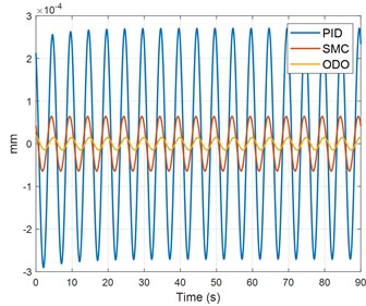
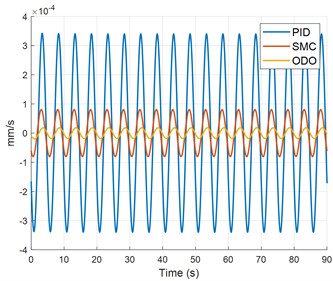
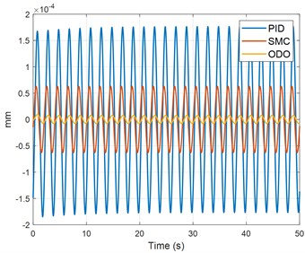
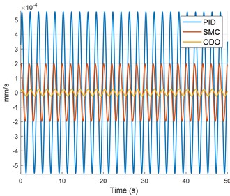
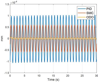
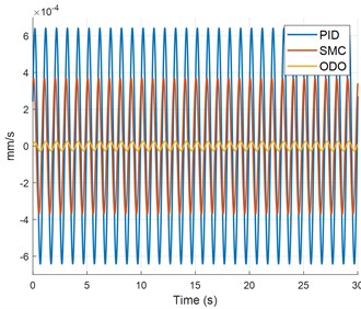
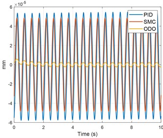
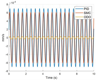
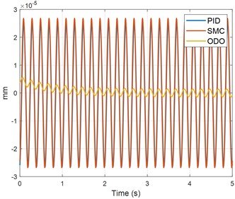
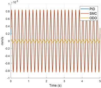
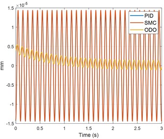
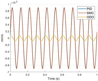
The Fig. 4 compares the displacement and velocity responses obtained using PID, sliding mode control (SMC), and the proposed output delay observer (ODO)-based control method under sinusoidal excitations at 0.1, 0.2, 0.5, 1, 2, 5, and 10 Hz. Subfigures (a), (c), (e), (g), (i), (k), and (m) present the displacement responses, whereas subfigures (b), (d), (f), (h), (j), (l), and (n) show the corresponding velocity responses. At the lower excitation frequencies, SMC produces smaller responses than PID, while the ODO method achieves the lowest displacement and velocity amplitudes. As the excitation frequency increases, the responses obtained using PID and SMC gradually approach each other and nearly overlap at some higher-frequency conditions; nevertheless, the ODO-controlled responses remain concentrated near zero and are substantially smaller.
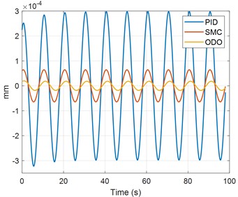
Fig. 4. Comparison of vibration suppression performance among PID, SMC, and ODO control methods at different excitation frequencies: a) displacement comparison among PID, SMC, and ODO at 0.1 Hz; b) velocity comparison among PID, SMC, and ODO at 0.1 Hz; c) displacement comparison among PID, SMC, and ODO at 0.2 Hz; d) velocity comparison among PID, SMC, and ODO at 0.2 Hz; e) displacement comparison among PID, SMC, and ODO at 0.5 Hz; f) velocity comparison among PID, SMC, and ODO at 0.5 Hz; g) displacement comparison among PID, SMC, and ODO at 1 Hz; h) velocity comparison among PID, SMC, and ODO at 1 Hz; i) displacement comparison among PID, SMC, and ODO at 2 Hz; j) velocity comparison among PID, SMC, and ODO at 2 Hz; k) displacement comparison among PID, SMC, and ODO at 5 Hz; l) velocity comparison among PID, SMC, and ODO at 5 Hz; m) displacement comparison among PID, SMC, and ODO at 10 Hz; n) velocity comparison among PID, SMC, and ODO at 10 Hz
Comparison of vibration suppression performance among PID, SMC, and ODO control methods at different excitation frequencies: a) displacement comparison among PID, SMC, and ODO at 0.1 Hz; b) velocity comparison among PID, SMC, and ODO at 0.1 Hz; c) displacement comparison among PID, SMC, and ODO at 0.2 Hz; d) velocity comparison among PID, SMC, and ODO at 0.2 Hz; e) displacement comparison among PID, SMC, and ODO at 0.5 Hz; f) velocity comparison among PID, SMC, and ODO at 0.5 Hz; g) displacement comparison among PID, SMC, and ODO at 1 Hz; h) velocity comparison among PID, SMC, and ODO at 1 Hz; i) displacement comparison among PID, SMC, and ODO at 2 Hz; j) velocity comparison among PID, SMC, and ODO at 2 Hz; k) displacement comparison among PID, SMC, and ODO at 5 Hz; l) velocity comparison among PID, SMC, and ODO at 5 Hz; m) displacement comparison among PID, SMC, and ODO at 10 Hz; n) velocity comparison among PID, SMC, and ODO at 10 Hz

a)

Comparison of vibration suppression performance among PID, SMC, and ODO control methods at different excitation frequencies: a) displacement comparison among PID, SMC, and ODO at 0.1 Hz; b) velocity comparison among PID, SMC, and ODO at 0.1 Hz; c) displacement comparison among PID, SMC, and ODO at 0.2 Hz; d) velocity comparison among PID, SMC, and ODO at 0.2 Hz; e) displacement comparison among PID, SMC, and ODO at 0.5 Hz; f) velocity comparison among PID, SMC, and ODO at 0.5 Hz; g) displacement comparison among PID, SMC, and ODO at 1 Hz; h) velocity comparison among PID, SMC, and ODO at 1 Hz; i) displacement comparison among PID, SMC, and ODO at 2 Hz; j) velocity comparison among PID, SMC, and ODO at 2 Hz; k) displacement comparison among PID, SMC, and ODO at 5 Hz; l) velocity comparison among PID, SMC, and ODO at 5 Hz; m) displacement comparison among PID, SMC, and ODO at 10 Hz; n) velocity comparison among PID, SMC, and ODO at 10 Hz

b)

Comparison of vibration suppression performance among PID, SMC, and ODO control methods at different excitation frequencies: a) displacement comparison among PID, SMC, and ODO at 0.1 Hz; b) velocity comparison among PID, SMC, and ODO at 0.1 Hz; c) displacement comparison among PID, SMC, and ODO at 0.2 Hz; d) velocity comparison among PID, SMC, and ODO at 0.2 Hz; e) displacement comparison among PID, SMC, and ODO at 0.5 Hz; f) velocity comparison among PID, SMC, and ODO at 0.5 Hz; g) displacement comparison among PID, SMC, and ODO at 1 Hz; h) velocity comparison among PID, SMC, and ODO at 1 Hz; i) displacement comparison among PID, SMC, and ODO at 2 Hz; j) velocity comparison among PID, SMC, and ODO at 2 Hz; k) displacement comparison among PID, SMC, and ODO at 5 Hz; l) velocity comparison among PID, SMC, and ODO at 5 Hz; m) displacement comparison among PID, SMC, and ODO at 10 Hz; n) velocity comparison among PID, SMC, and ODO at 10 Hz

c)

Comparison of vibration suppression performance among PID, SMC, and ODO control methods at different excitation frequencies: a) displacement comparison among PID, SMC, and ODO at 0.1 Hz; b) velocity comparison among PID, SMC, and ODO at 0.1 Hz; c) displacement comparison among PID, SMC, and ODO at 0.2 Hz; d) velocity comparison among PID, SMC, and ODO at 0.2 Hz; e) displacement comparison among PID, SMC, and ODO at 0.5 Hz; f) velocity comparison among PID, SMC, and ODO at 0.5 Hz; g) displacement comparison among PID, SMC, and ODO at 1 Hz; h) velocity comparison among PID, SMC, and ODO at 1 Hz; i) displacement comparison among PID, SMC, and ODO at 2 Hz; j) velocity comparison among PID, SMC, and ODO at 2 Hz; k) displacement comparison among PID, SMC, and ODO at 5 Hz; l) velocity comparison among PID, SMC, and ODO at 5 Hz; m) displacement comparison among PID, SMC, and ODO at 10 Hz; n) velocity comparison among PID, SMC, and ODO at 10 Hz

d)

Comparison of vibration suppression performance among PID, SMC, and ODO control methods at different excitation frequencies: a) displacement comparison among PID, SMC, and ODO at 0.1 Hz; b) velocity comparison among PID, SMC, and ODO at 0.1 Hz; c) displacement comparison among PID, SMC, and ODO at 0.2 Hz; d) velocity comparison among PID, SMC, and ODO at 0.2 Hz; e) displacement comparison among PID, SMC, and ODO at 0.5 Hz; f) velocity comparison among PID, SMC, and ODO at 0.5 Hz; g) displacement comparison among PID, SMC, and ODO at 1 Hz; h) velocity comparison among PID, SMC, and ODO at 1 Hz; i) displacement comparison among PID, SMC, and ODO at 2 Hz; j) velocity comparison among PID, SMC, and ODO at 2 Hz; k) displacement comparison among PID, SMC, and ODO at 5 Hz; l) velocity comparison among PID, SMC, and ODO at 5 Hz; m) displacement comparison among PID, SMC, and ODO at 10 Hz; n) velocity comparison among PID, SMC, and ODO at 10 Hz

e)

Comparison of vibration suppression performance among PID, SMC, and ODO control methods at different excitation frequencies: a) displacement comparison among PID, SMC, and ODO at 0.1 Hz; b) velocity comparison among PID, SMC, and ODO at 0.1 Hz; c) displacement comparison among PID, SMC, and ODO at 0.2 Hz; d) velocity comparison among PID, SMC, and ODO at 0.2 Hz; e) displacement comparison among PID, SMC, and ODO at 0.5 Hz; f) velocity comparison among PID, SMC, and ODO at 0.5 Hz; g) displacement comparison among PID, SMC, and ODO at 1 Hz; h) velocity comparison among PID, SMC, and ODO at 1 Hz; i) displacement comparison among PID, SMC, and ODO at 2 Hz; j) velocity comparison among PID, SMC, and ODO at 2 Hz; k) displacement comparison among PID, SMC, and ODO at 5 Hz; l) velocity comparison among PID, SMC, and ODO at 5 Hz; m) displacement comparison among PID, SMC, and ODO at 10 Hz; n) velocity comparison among PID, SMC, and ODO at 10 Hz

f)

Comparison of vibration suppression performance among PID, SMC, and ODO control methods at different excitation frequencies: a) displacement comparison among PID, SMC, and ODO at 0.1 Hz; b) velocity comparison among PID, SMC, and ODO at 0.1 Hz; c) displacement comparison among PID, SMC, and ODO at 0.2 Hz; d) velocity comparison among PID, SMC, and ODO at 0.2 Hz; e) displacement comparison among PID, SMC, and ODO at 0.5 Hz; f) velocity comparison among PID, SMC, and ODO at 0.5 Hz; g) displacement comparison among PID, SMC, and ODO at 1 Hz; h) velocity comparison among PID, SMC, and ODO at 1 Hz; i) displacement comparison among PID, SMC, and ODO at 2 Hz; j) velocity comparison among PID, SMC, and ODO at 2 Hz; k) displacement comparison among PID, SMC, and ODO at 5 Hz; l) velocity comparison among PID, SMC, and ODO at 5 Hz; m) displacement comparison among PID, SMC, and ODO at 10 Hz; n) velocity comparison among PID, SMC, and ODO at 10 Hz

g)

Comparison of vibration suppression performance among PID, SMC, and ODO control methods at different excitation frequencies: a) displacement comparison among PID, SMC, and ODO at 0.1 Hz; b) velocity comparison among PID, SMC, and ODO at 0.1 Hz; c) displacement comparison among PID, SMC, and ODO at 0.2 Hz; d) velocity comparison among PID, SMC, and ODO at 0.2 Hz; e) displacement comparison among PID, SMC, and ODO at 0.5 Hz; f) velocity comparison among PID, SMC, and ODO at 0.5 Hz; g) displacement comparison among PID, SMC, and ODO at 1 Hz; h) velocity comparison among PID, SMC, and ODO at 1 Hz; i) displacement comparison among PID, SMC, and ODO at 2 Hz; j) velocity comparison among PID, SMC, and ODO at 2 Hz; k) displacement comparison among PID, SMC, and ODO at 5 Hz; l) velocity comparison among PID, SMC, and ODO at 5 Hz; m) displacement comparison among PID, SMC, and ODO at 10 Hz; n) velocity comparison among PID, SMC, and ODO at 10 Hz

h)

Comparison of vibration suppression performance among PID, SMC, and ODO control methods at different excitation frequencies: a) displacement comparison among PID, SMC, and ODO at 0.1 Hz; b) velocity comparison among PID, SMC, and ODO at 0.1 Hz; c) displacement comparison among PID, SMC, and ODO at 0.2 Hz; d) velocity comparison among PID, SMC, and ODO at 0.2 Hz; e) displacement comparison among PID, SMC, and ODO at 0.5 Hz; f) velocity comparison among PID, SMC, and ODO at 0.5 Hz; g) displacement comparison among PID, SMC, and ODO at 1 Hz; h) velocity comparison among PID, SMC, and ODO at 1 Hz; i) displacement comparison among PID, SMC, and ODO at 2 Hz; j) velocity comparison among PID, SMC, and ODO at 2 Hz; k) displacement comparison among PID, SMC, and ODO at 5 Hz; l) velocity comparison among PID, SMC, and ODO at 5 Hz; m) displacement comparison among PID, SMC, and ODO at 10 Hz; n) velocity comparison among PID, SMC, and ODO at 10 Hz

i)

Comparison of vibration suppression performance among PID, SMC, and ODO control methods at different excitation frequencies: a) displacement comparison among PID, SMC, and ODO at 0.1 Hz; b) velocity comparison among PID, SMC, and ODO at 0.1 Hz; c) displacement comparison among PID, SMC, and ODO at 0.2 Hz; d) velocity comparison among PID, SMC, and ODO at 0.2 Hz; e) displacement comparison among PID, SMC, and ODO at 0.5 Hz; f) velocity comparison among PID, SMC, and ODO at 0.5 Hz; g) displacement comparison among PID, SMC, and ODO at 1 Hz; h) velocity comparison among PID, SMC, and ODO at 1 Hz; i) displacement comparison among PID, SMC, and ODO at 2 Hz; j) velocity comparison among PID, SMC, and ODO at 2 Hz; k) displacement comparison among PID, SMC, and ODO at 5 Hz; l) velocity comparison among PID, SMC, and ODO at 5 Hz; m) displacement comparison among PID, SMC, and ODO at 10 Hz; n) velocity comparison among PID, SMC, and ODO at 10 Hz

j)

Comparison of vibration suppression performance among PID, SMC, and ODO control methods at different excitation frequencies: a) displacement comparison among PID, SMC, and ODO at 0.1 Hz; b) velocity comparison among PID, SMC, and ODO at 0.1 Hz; c) displacement comparison among PID, SMC, and ODO at 0.2 Hz; d) velocity comparison among PID, SMC, and ODO at 0.2 Hz; e) displacement comparison among PID, SMC, and ODO at 0.5 Hz; f) velocity comparison among PID, SMC, and ODO at 0.5 Hz; g) displacement comparison among PID, SMC, and ODO at 1 Hz; h) velocity comparison among PID, SMC, and ODO at 1 Hz; i) displacement comparison among PID, SMC, and ODO at 2 Hz; j) velocity comparison among PID, SMC, and ODO at 2 Hz; k) displacement comparison among PID, SMC, and ODO at 5 Hz; l) velocity comparison among PID, SMC, and ODO at 5 Hz; m) displacement comparison among PID, SMC, and ODO at 10 Hz; n) velocity comparison among PID, SMC, and ODO at 10 Hz

k)

Comparison of vibration suppression performance among PID, SMC, and ODO control methods at different excitation frequencies: a) displacement comparison among PID, SMC, and ODO at 0.1 Hz; b) velocity comparison among PID, SMC, and ODO at 0.1 Hz; c) displacement comparison among PID, SMC, and ODO at 0.2 Hz; d) velocity comparison among PID, SMC, and ODO at 0.2 Hz; e) displacement comparison among PID, SMC, and ODO at 0.5 Hz; f) velocity comparison among PID, SMC, and ODO at 0.5 Hz; g) displacement comparison among PID, SMC, and ODO at 1 Hz; h) velocity comparison among PID, SMC, and ODO at 1 Hz; i) displacement comparison among PID, SMC, and ODO at 2 Hz; j) velocity comparison among PID, SMC, and ODO at 2 Hz; k) displacement comparison among PID, SMC, and ODO at 5 Hz; l) velocity comparison among PID, SMC, and ODO at 5 Hz; m) displacement comparison among PID, SMC, and ODO at 10 Hz; n) velocity comparison among PID, SMC, and ODO at 10 Hz

l)

Comparison of vibration suppression performance among PID, SMC, and ODO control methods at different excitation frequencies: a) displacement comparison among PID, SMC, and ODO at 0.1 Hz; b) velocity comparison among PID, SMC, and ODO at 0.1 Hz; c) displacement comparison among PID, SMC, and ODO at 0.2 Hz; d) velocity comparison among PID, SMC, and ODO at 0.2 Hz; e) displacement comparison among PID, SMC, and ODO at 0.5 Hz; f) velocity comparison among PID, SMC, and ODO at 0.5 Hz; g) displacement comparison among PID, SMC, and ODO at 1 Hz; h) velocity comparison among PID, SMC, and ODO at 1 Hz; i) displacement comparison among PID, SMC, and ODO at 2 Hz; j) velocity comparison among PID, SMC, and ODO at 2 Hz; k) displacement comparison among PID, SMC, and ODO at 5 Hz; l) velocity comparison among PID, SMC, and ODO at 5 Hz; m) displacement comparison among PID, SMC, and ODO at 10 Hz; n) velocity comparison among PID, SMC, and ODO at 10 Hz

m)

Comparison of vibration suppression performance among PID, SMC, and ODO control methods at different excitation frequencies: a) displacement comparison among PID, SMC, and ODO at 0.1 Hz; b) velocity comparison among PID, SMC, and ODO at 0.1 Hz; c) displacement comparison among PID, SMC, and ODO at 0.2 Hz; d) velocity comparison among PID, SMC, and ODO at 0.2 Hz; e) displacement comparison among PID, SMC, and ODO at 0.5 Hz; f) velocity comparison among PID, SMC, and ODO at 0.5 Hz; g) displacement comparison among PID, SMC, and ODO at 1 Hz; h) velocity comparison among PID, SMC, and ODO at 1 Hz; i) displacement comparison among PID, SMC, and ODO at 2 Hz; j) velocity comparison among PID, SMC, and ODO at 2 Hz; k) displacement comparison among PID, SMC, and ODO at 5 Hz; l) velocity comparison among PID, SMC, and ODO at 5 Hz; m) displacement comparison among PID, SMC, and ODO at 10 Hz; n) velocity comparison among PID, SMC, and ODO at 10 Hz

n)

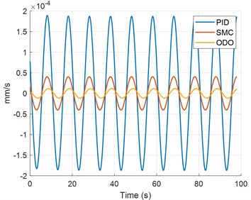
Following a brief initial transient, the ODO responses converge to low-amplitude steady-state oscillations, demonstrating superior vibration attenuation and satisfactory convergence over the investigated frequency range. Overall, the results indicate that the proposed ODO controller provides the most effective suppression of both platform displacement and velocity compared with PID and SMC. the PID controller gains were fixed at Kp= 600, Ki= 100, and Kd= 400. for the SMC method, the sliding surface was defined as s=x˙+λx, with λ= 15. The reaching gain and boundary-layer thickness were set to η= 0.06 and ϕ= 0.003, respectively. These parameters were kept unchanged for all excitation frequencies and disturbance conditions. No frequency-dependent retuning was performed.
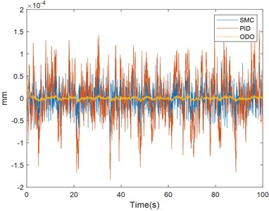
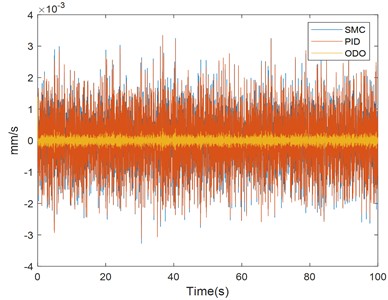
Fig. 5. Comparison of the displacement and velocity responses of the PID, SMC, and ODO active vibration-isolation methods under identical band-limited Gaussian white-noise excitation: a) displacement comparison among PID, SMC, and ODO under white-noise excitation; b) velocity comparison among PID, SMC, and ODO under white-noise excitation
Comparison of the displacement and velocity responses of the PID, SMC, and ODO active vibration-isolation methods under identical band-limited Gaussian white-noise excitation:  a) displacement comparison among PID, SMC, and ODO under white-noise excitation;  b) velocity comparison among PID, SMC, and ODO under white-noise excitation

a)

Comparison of the displacement and velocity responses of the PID, SMC, and ODO active vibration-isolation methods under identical band-limited Gaussian white-noise excitation:  a) displacement comparison among PID, SMC, and ODO under white-noise excitation;  b) velocity comparison among PID, SMC, and ODO under white-noise excitation

b)

Fig. 5 compares the PID, SMC, and ODO isolation methods under identical zero-mean Gaussian white-noise excitation, band-limited to 0.05-20 Hz with an RMS displacement of 1 mm, a sampling interval of 0.001 s, and a duration of 100 s. the PID method produces the largest displacement fluctuations, SMC provides moderate attenuation, and the ODO method achieves the smallest displacement and velocity responses, demonstrating superior broadband vibration suppression.

The Fig. 6 presents the measured ground-vibration acceleration amplitude spectral density on logarithmic axes, together with the Peterson New High Noise Model (NHNM) and New Low Noise Model (NLNM) reference curves. the blue solid line represents the measured ground-vibration noise, while the red and yellow dashed lines denote the NHNM and NLNM, Overall, the measured noise lies mainly between the two reference models over the effective frequency range and increases noticeably at 0.1-0.3 Hz and above 10 Hz, reflecting the ground-vibration characteristics of the measurement environment across different frequency bands respectively.
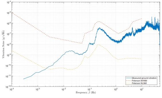
Fig. 6. Acceleration amplitude spectral density of the measured ground vibration compared with the Peterson NHNM and NLNM
Acceleration amplitude spectral density of the measured ground vibration compared  with the Peterson NHNM and NLNM

The measured ground-vibration data were acquired using a Güralp 3ESPC triaxial broadband seismometer. the instrument has a standard frequency response of 60 s-100 Hz, while its self-noise is below the Peterson New Low Noise Model over approximately 30 s-10 Hz. the standard differential velocity-output sensitivity is 2×750 V/(m/s); however, the calibration coefficient supplied with the specific instrument was used for data conversion. The vertical ground-velocity component was sampled at 100 Hz, corresponding to a sampling interval of 0.01 s, and was converted to velocity units before being used as the disturbance input. The sensor was levelled and rigidly coupled to the measurement surface to reduce installation-induced errors.

The measured ground-velocity signal was sampled at 100 Hz and converted to velocity units using the seismometer calibration coefficient. the mean value and linear trend were removed before analysis. The corresponding ground displacement was obtained by integrating the detrended velocity signal. The same measured vibration record, initial conditions, simulation duration, and controller parameters were used for the ODO, PID, and SMC methods. After removing the initial transient, the acceleration amplitude spectral density (ASD) of the vibration before and after isolation was calculated using Welch’s method. Identical window, overlap, and FFT settings were adopted for all control methods. The ASD was expressed in g/√Hz, and its values at 0.1, 0.2, 0.5, 1, 2, 5, and 10 Hz were obtained by interpolation of the calculated ASD spectrum. The frequency-dependent suppression ratio was defined as:

23
Rfi=1-AfiA0fi×100 %,

where A0fi is the acceleration ASD before active vibration isolation and Afi is the residual acceleration ASD obtained using the ODO, PID, or SMC controller at frequency fi. Table 2 compares the acceleration amplitude spectral density before vibration isolation and after applying the ODO, PID, and SMC controllers at 0.1, 0.2, 0.5, 1, 2, 5, and 10 Hz. All three control methods reduce the vibration noise, with ODO producing the lowest residual response at every frequency. Specifically, ODO reduces the amplitude spectral density from 10-8-10-7 g/√Hz before isolation to 10-11-10-9 g/√Hz, corresponding to suppression ratios of 98.15 %-99.88 %. in comparison, the suppression ratios achieved by PID and SMC range from 70.25 % to 98.65 % and from 93.56 % to 98.61 %, respectively. Moreover, ODO further reduces the residual vibration noise by approximately 91.13 %-95.95 % relative to PID and by 71.30 %-95.21 % relative to SMC, demonstrating superior and consistent broadband vibration suppression over the frequency range of 0.1-10 Hz.

Table 2. Performance Improvement Achieved by Active Vibration Isolation
Frequency (Hz)
Before vibration (g/√Hz)
ODO (g/√Hz)
PID (g/√Hz)
SMC (g/√Hz)
0.1
1.1612×10⁻⁸
2.1444×10⁻¹⁰
3.4547×10⁻⁹
7.4726×10⁻¹⁰
0.2
1.3404×10⁻⁷
1.9440×10⁻⁹
3.6243×10⁻⁸
8.6011×10⁻⁹
0.5
5.3825×10⁻⁸
4.1041×10⁻¹⁰
9.5077×10⁻⁹
3.3861×10⁻⁹
1
1.2915×10⁻⁸
5.3353×10⁻¹¹
1.3184×10⁻⁹
7.6131×10⁻¹⁰
2
3.5464×10⁻⁸
8.2168×10⁻¹¹
1.9655×10⁻⁹
1.7137×10⁻⁹
5
4.9117×10⁻⁸
6.8749×10⁻¹¹
1.2456×10⁻⁹
1.3014×10⁻⁹
10
2.6469×10⁻⁷
3.1623×10⁻¹⁰
3.5648×10⁻⁹
3.6669×10⁻⁹

As illustrated in Fig. 7, the atom-interference phase is highly sensitive to low-frequency vibrations. When the vibration frequency exceeds a certain threshold, the magnitude of the sensitivity function gradually decreases, indicating that the cold atom gravimeter is more sensitive to vibration disturbances in the frequency range below 10 Hz.
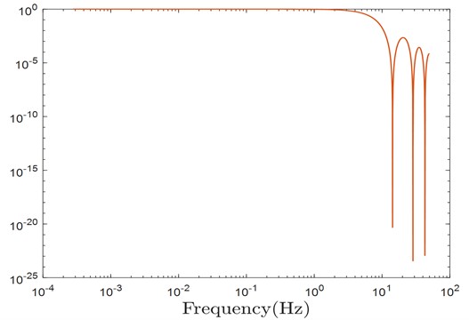
Fig. 7. Vibration sensitivity function of the cold atom gravimeter
Vibration sensitivity function of the cold atom gravimeter

Based on this sensitivity characteristic, the influence of vibration on the cold atom gravimeter can be evaluated using the following expression:

24
σg2=∫0∞16sin4ωT/2ωT42Saωdω,

where, Saω denotes the power spectral density of vibration noise, ω represents the angular frequency of the vibration, and T corresponds to the free evolution time of the atoms during the interferometric sequence. The analysis indicates that, for different interference times, low-frequency vibration noise contributes significantly to the sensitivity of the cold atom gravimeter. The corresponding sensitivity functions are illustrated in Fig. 7.
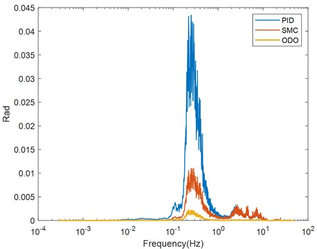
Fig. 8. Phase noise contribution of the cold atom gravimeter after vibration suppression
Phase noise contribution of the cold atom gravimeter after vibration suppression

Fig. 8 compares the effects of residual vibration noise on the phase of the cold-atom gravimeter under SMC, PID, and ODO control. the residual phase disturbances are mainly concentrated in the low-frequency range and decrease rapidly with increasing frequency. PID still exhibits pronounced low-frequency peaks and fluctuations, whereas SMC further reduces the phase disturbance, and the ODO response remains closest to zero.

The phase-noise standard deviations obtained using ODO, PID, and SMC are 7.05×10⁻⁴, 1.44×10⁻², and 4.69×10⁻³ rad, respectively. Compared with PID and SMC, ODO reduces the phase noise by approximately 95.10 % and 84.95 %, respectively, demonstrating its superior ability to suppress vibration-induced atomic-interference phase noise and thereby improve the sensitivity and stability of cold atom gravity measurements.

6. Conclusions

This study proposes an active vibration-isolation control method based on an output-delay observer combined with proportional-derivative control for a cold-atom gravimeter. Stability analysis confirms that the closed-loop system is asymptotically stable under constant or slowly varying disturbances and uniformly ultimately bounded under bounded time-varying disturbances. Simulations under sinusoidal, white-noise, and measured ground-vibration excitations show that the proposed method outperforms PID and SMC. It achieves vibration suppression ratios of 98.15 %-99.88 % over 0.1-10 Hz and reduces the phase-noise standard deviation to 7.05×10⁻⁴ rad, corresponding to reductions of 95.10 % and 84.95 % relative to PID and SMC. Future work will focus on experimental validation under practical operating conditions.

It should be noted that the present work is mainly based on numerical simulation. Although measured ambient ground-vibration data were used as disturbance inputs to improve the realism of the simulation, the proposed ODO controller has not yet been experimentally implemented on a physical active vibration-isolation platform or integrated with a cold-atom gravimeter. Therefore, practical factors such as actuator saturation, sensor self-noise, analog-to-digital conversion delay, power-amplifier dynamics, structural coupling, nonlinear friction, and real-time computational delay are not fully considered in the current model.

Future work will focus on experimental validation and real-world implementation. First, the proposed controller will be implemented on a real-time control unit and tested on a laboratory active vibration isolation platform equipped with vibration sensors, a voice-coil actuator, and a displacement/velocity measurement system. Harmonic excitation, white-noise excitation, and measured ground-vibration disturbance will be applied to evaluate the residual displacement, residual velocity, frequency-domain vibration attenuation, and control effort. Second, the validated isolation platform will be integrated with a cold-atom gravimeter to evaluate the residual vibration of the Raman retro-reflection mirror, the vibration-induced interferometric phase noise, and the corresponding improvement in gravity-measurement sensitivity. This staged experimental plan will provide a direct verification of the practical applicability of the proposed ODO vibration isolation method.

References

  • B. Cheng et al., “Experiment on dynamic absolute gravity measurement based on cold atom gravimeter,” Acta Physica Sinica, Vol. 71, No. 2, p. 026701, Jan. 2022, https://doi.org/10.7498/aps.71.20211449
  • Z. X. Liu et al., “Experimental study on high-precision cold atom absolute gravimeter in complex field environment,” (in Chinese), Optics and Optoelectronics Technology, Vol. 23, No. 2, pp. 18–24, 2025, https://doi.org/10.19519/j.cnki.1672-3392.2025.02.002
  • C. Zhai et al., “Airborne absolute gravity measurements based on quantum gravimeter,” Acta Physica Sinica, Vol. 74, No. 7, p. 070302, Feb. 2025, https://doi.org/10.7498/aps.74.20241621
  • Y. Zhang, “Measurement and evaluation of working environment noise for atomic gravimeter,” (in Chinese), Huazhong University of Science and Technology, 2023, https://doi.org/10.27157/d.cnki.ghzku.2023.005467
  • T. Zhang et al., “Ultrahigh-sensitivity Bragg atom gravimeter and its application in testing Lorentz violation,” Physical Review Applied, Vol. 20, No. 1, Jul. 2023, https://doi.org/10.1103/physrevapplied.20.014067
  • Z.-K. Hu et al., “Demonstration of an ultrahigh-sensitivity atom-interferometry absolute gravimeter,” Physical Review A, Vol. 88, No. 4, Oct. 2013, https://doi.org/10.1103/physreva.88.043610
  • P. G. Nelson, “An active vibration isolation system for inertial reference and precision measurement,” Review of Scientific Instruments, Vol. 62, No. 9, pp. 2069–2075, Sep. 1991, https://doi.org/10.1063/1.1142368
  • J. Le Gouët et al., “Limits to the sensitivity of a low-noise compact atomic gravimeter,” Applied Physics B, Vol. 92, No. 2, pp. 133–144, 2008, https://doi.org/10.1007/s00340-008-3088-1
  • A. Xu, D. Kong, Z. Fu, Z. Wang, and Q. Lin, “Vibration compensation of an atom gravimeter,” Chinese Optics Letters, Vol. 17, No. 7, p. 070201, Jul. 2019, https://doi.org/10.3788/col201917.070201
  • J. M. Hensley, A. Peters, and S. Chu, “Active low-frequency vertical vibration isolation,” Review of Scientific Instruments, Vol. 70, No. 6, pp. 2735–2741, 1999, https://doi.org/10.1063/1.1149838
  • C. Freier, “Measurement of local gravity using atom interferometry,” Humboldt-Universität zu Berlin, Humboldt-Universität zu Berlin, Berlin, Germany, 2010.
  • B. Tang, L. Zhou, Z. Xiong, J. Wang, and M. Zhan, “A programmable broadband low-frequency active vibration isolation system for atom interferometry,” Review of Scientific Instruments, Vol. 85, No. 9, 2014, https://doi.org/10.1063/1.4895911
  • W. Gong, A. Li, J. Ma, P. Wu, and F. Qin, “An ultralow-frequency vertical isolation system based on composite feedforward and feedback control,” IEEE Sensors Journal, Vol. 23, No. 23, pp. 29109–29118, 2023, https://doi.org/10.1109/jsen.2023.3321920
  • F. E. Oon and R. Dumke, “Compact active vibration isolation and tilt stabilization for a portable high-precision atomic gravimeter,” Physical Review Applied, Vol. 18, No. 4, Oct. 2022, https://doi.org/10.1103/physrevapplied.18.044037
  • J. Yao, K. Wu, J. Qian, G. Wang, M. Guo, and L. Wang, “An ultra-low frequency active vertical vibration isolator with geometric anti-spring structure,” in Volume 4B: Dynamics, Vibration, and Control, pp. 3–7, 2017, https://doi.org/10.1115/imece2017-71173
  • K. Wu, G. Li, H. Hu, and L. Wang, “Active low-frequency vertical vibration isolation system for precision measurements,” Chinese Journal of Mechanical Engineering, Vol. 30, No. 1, pp. 164–169, Jun. 2016, https://doi.org/10.3901/cjme.2016.0428.062
  • M.-K. Zhou et al., “Performance of a cold-atom gravimeter with an active vibration isolator,” Physical Review A, Vol. 86, No. 4, Oct. 2012, https://doi.org/10.1103/physreva.86.043630
  • M.-K. Zhou, X. Xiong, L.-L. Chen, J.-F. Cui, X.-C. Duan, and Z.-K. Hu, “Note: a three-dimension active vibration isolator for precision atom gravimeters,” Review of Scientific Instruments, Vol. 86, No. 4, 2015, https://doi.org/10.1063/1.4919292
  • B. Chen, J.-B. Long, H.-T. Xie, L.-K. Chen, and S. Chen, “A mobile three-dimensional active vibration isolator and its application to cold atom interferometry,” Acta Physica Sinica, Vol. 68, No. 18, p. 183301, 2020, https://doi.org/10.7498/aps.68.20190443
  • F. Saltari, F. Mastroddi, L. Pustina, M. V. G. Muniz, and A. Argiolas, “eVTOL flutter analyses in wingborne flight via ground vibration test data and actuator failure effects on stability,” Aerospace Science and Technology, Vol. 167, p. 110674, Jul. 2025, https://doi.org/10.1016/j.ast.2025.110674
  • Y. P. Zhu, S. Y. Yang, and Q. S. Wang, “Current control strategy of interior permanent magnet synchronous motor based on a delay-corrected extended state observer,” (in Chinese), Transactions of China Electrotechnical Society, Vol. 39, No. 6, pp. 1698–1712, 2024, https://doi.org/10.19595/j.cnki.1000-6753.tces.222286
  • C. Ruan et al., “A transportable atomic gravimeter with constraint-structured active vibration isolation,” Sensors, Vol. 24, No. 8, p. 2395, Apr. 2024, https://doi.org/10.3390/s24082395
  • D. Ling, T. Jiang, J. Sun, and Y. Wang, “Data-driven diagnosis of model-plant mismatch in MIMO closed-loop control systems,” ACS Omega, Vol. 10, No. 15, pp. 15148–15158, 2025, https://doi.org/10.1021/acsomega.4c10798
  • W. W. Zhang, “Reliability analysis of low-frequency vibration suppression for permanent magnet synchronous motors in new-energy vehicles,” (in Chinese), Environmental Technology, Vol. 41, No. 11, pp. 42–47, 2023, https://doi.org/10.3969/j.issn.1004-7204.2023.11.015
  • J. Tan et al., “Measurement of Raman beam inclination changes in a cold atom gravimeter based on Raman beam interference,” Chinese Optics Letters, Vol. 23, No. 11, p. 111104, Sep. 2025, https://doi.org/10.3788/col202523.111104
  • M. Guo et al., “A vibration correction system for cold atom gravimeter,” Measurement Science and Technology, Vol. 35, No. 3, p. 035011, 2024, https://doi.org/10.1088/1361-6501/ad128d
  • P. Chen et al., “The research on the effect of dynamic tilt variation on the phase of cold atomic gravimeter,” Applied Physics B, Vol. 130, No. 7, 2024, https://doi.org/10.1007/s00340-024-08243-8
  • K. Wang et al., “Accurate evaluation of the scale factor for a gPhone relative gravimeter with a stable cold atom gravimeter,” IEEE Sensors Journal, Vol. 25, No. 17, pp. 32326–32336, Sep. 2025, https://doi.org/10.1109/jsen.2025.3589769
  • M. Di Ferdinando, G. Pola, S. Di Gennaro, P. Pepe, and A. Borri, “On the design and the digital implementation of observer-based controllers for tracking of nonlinear time-delay systems,” International Journal of Robust and Nonlinear Control, Vol. 34, No. 10, pp. 6582–6609, 2024, https://doi.org/10.1002/rnc.7182
  • K. Ming, Q. Zhang, and W. Gu, “Fast steering mirror control based on fuzzy proportional-integral-derivative control,” (in Chinese), Laser and Optoelectronics Progress, Vol. 62, No. 1, p. 0123001, 2025, https://doi.org/10.3788/lop240869

About this article

Received
March 12, 2026
Accepted
August 30, 2026
Published
November 16, 2026
SUBJECTS
Vibration control, generation and harvesting
Keywords
active vibration isolation
cold atom gravimeter
delay observer
vibration noise
Acknowledgements

This research was funded by Science and Technology Project of the Jiangxi Provincial Department of Education, grant number GJJ190910.

Data Availability

The datasets generated during and/or analyzed during the current study are available from the corresponding author on reasonable request.

Author Contributions

Dongyun Luo: investigation, methodology. Xingyang Luo: writing-original draft. Shili Long: writing-review and editing. Changshou Deng: supervision.

Conflict of interest

The authors declare that they have no conflict of interest.